Maximum Error Modeling for Fault-Tolerant Computation using Maximum a posteriori (MAP) Hypothesis
The application of current generation computing machines in safety-centric applications like implantable biomedical chips and automobile safety has immensely increased the need for reviewing the worst-case error behavior of computing devices for faul…
Authors: Karthikeyan Lingasubramanian, Syed M. Alam, Sanjukta Bhanja
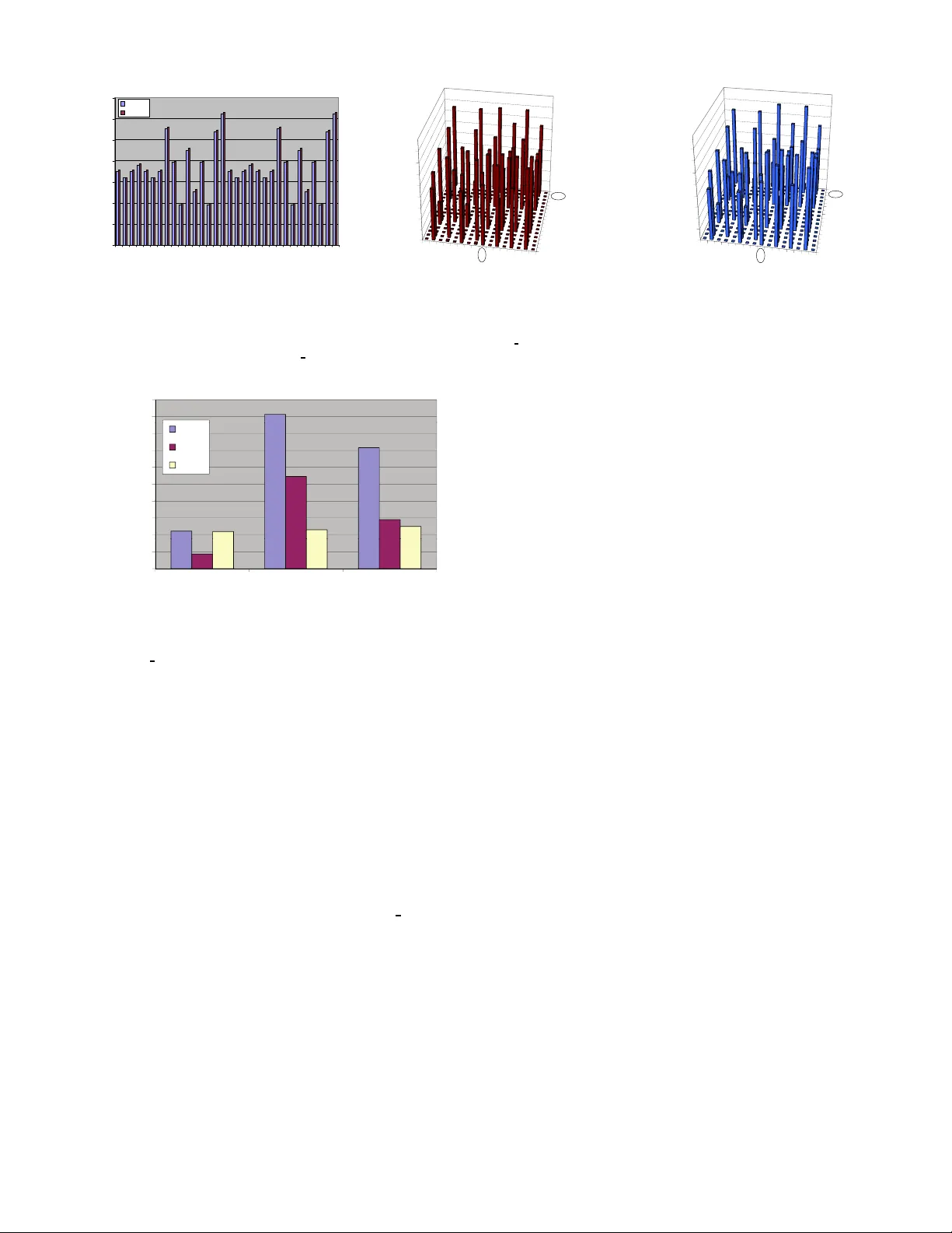
1 Maximum Error Modeling for F ault-T olerant Computation using Maximum a posteriori (MAP) Hypothesis Karthikeyan Lingasub ramanian + , Syed M. Alam ∗ , Sanjukta Bh anja + + Nano Comp uting R esearch Gr oup (NCRG), Depa rtment of Electrica l Engine ering, University o f South Florida ∗ EverSp in T echnologies Abstract The app lication o f curr ent generatio n computin g machines in safety-centric applications li ke implantable biomedical chips and automob ile safety has immensely increased the need for revie wing the w orst-case error behavior of computin g devices for fault-tolerant compu tation. In this work, we propose an exact pro babilistic erro r mod el tha t can comp ute the maximum error over all possible input space in a circuit-specific ma nner and ca n handle various types o f structural depend encies in the circuit. W e also provide the worst-case input vector , which h as th e highest p robab ility to gen erate an erro neous output, for any given logic circu it. W e also p resent a study of circu it-specific error bo unds for fault-toler ant co mputatio n in hete rogene ous circuits using the max imum error computed for each circuit. W e model the error estimation pro blem as a maximum a p osteriori (MAP) estimate, over the joint erro r probab ility func tion o f the entire circuit, calcu lated efficiently throug h an intelligent search of the entire input space using probab ilistic trav ersal of a binary join tree using Shenoy-Sh afer algorithm . W e de monstrate this m odel u sing MCNC and ISCAS benchmar k circuits and validate it using an equiv alent HSpice model. Both results yield the same worst-case input vectors and the high est % difference of o ur e rror model over HSpice is just 1 . 23 %. W e o bserve that the max imum err or probab ilities are sign ificantly larger than the average erro r probab ilities, and provides a mu ch tighter er ror bou nds f or fault-tolerant comp utation. W e also find that the error estimates depend on the specific circuit structure and the max imum error pr obabilities are sensiti ve to the ind ividual gate f ailure probab ilities. I . I N T RO D U C T I O N Why maximum error? Industries like automotive and health care, which employs safety-cen tric elec tronic devices, have traditio nally addressed high reliability requirem ents by employing r edund ancy , error co rrections, a nd choice o f p roper assembly and pa ckaging technolog y . I n addition , rig orous produ ct testing at e xtended stress co ndition s filters out e ven an entire lot in the presence of a small numb er of fail- ures [38]. Ano ther r apidly growing class of electronic chips where reliab ility is very critical in implantable bio medical chips [4 0], [41]. More inter estingly , som e of the safety ap- proach es, such as redun dancy a nd complex p ackaging , are not read ily app licable to im plantable bio medical ap plications because of low voltage, low power operation a nd small form factor requir ements. Also in future technologies like NW - FET , CNT -FET [43], R TD [45], hyb rid n ano devices [15], single electron tunneling de vices [16 ], field coupled computing devices like QCA ’ s [44] ( molecular and magnetic) an d spin- coupled computing de vices, computin g comp onents are likely to have higher error rates (both in terms of defec t and tran sient faults) since they ope rate near the thermal limit a nd infor- mation pr ocessing occurs at extr emely small volu me. Nan o- CMOS, beyond 22nm, is not an exception in this regard as the frequency scales up and v o ltage and geometry scales down. Also we h ave to n ote that, while tw o d esign implementa tion choices can have d iffer ent average pr oba bilities of failur es, the lower aver age choice may in fact h ave highe r maximum pr ob ability of failure leading to lower yield in manu facturing and mor e r ejects during chip burn-in and extended scr eening. A. Pr o posed W ork In this work, we present a pr obabilistic mo del to study the maximu m output error over all possible input space fo r a giv en logic circuit. W e present a meth od to find out the worst- case inpu t vector, i.e ., the in put vector that has the highest probab ility to give an error at th e outpu t. In the first step of our mod el, we convert the circuit into a correspon ding edge- minimal prob abilistic network that represents the basic logic function o f th e cir cuit by hand ling the interdepen dencies be- tween the signals u sing random variables o f interest in a com- posite jo int prob ability distribution f unction P ( y 1 , y 2 , · · · , y N ) . Each node in this network c orrespo nds to a r andom variable representin g a signal in the d igital circuit, an d e ach e dge correspo nds to the logic g overning the conn ected signa ls. The individual prob ability distribution for each node is given using condition al probability tab les. From this pro babilistic n etwork we obta in our probab ilistic error model th at con sists of thr ee blocks, (i) ideal error free logic, (ii) erro r pro ne logic where e very gate has a g ate err or probab ility ε i.e ., each gate can go wron g individually by a prob abilistic factor ε and (iii) a detection un it tha t uses compara tors to comp are the err or free and erron eous outpu ts. 2 The error prone logic represents the real time circuit under test, whereas th e ideal logic and the detection unit are fictitious elements used to study th e circuit. Both the ideal lo gic and error p rone logic would be fed by the prima ry inpu ts I . W e denote all the intern al nod es, both in the error f ree and erroneo us portions, by X and the compara tor outputs as O . The co mparato rs are b ased o n XOR lo gic an d hence a state ”1” would signify error at the o utput. An evidence set o is created by evidencing one or m ore of the variables in the compara tor set O to state ”1 ” ( P ( O i = 1 ) = 1). Then perfo rm- ing MAP hypothesis on the prob abilistic error model provid es the worst-case input vector i MA P which gives max ∀ i P ( i , o ) . The max imum outp ut error pro bability can be obtain ed from P ( O i = 1 ) after instantiating the inp ut nod es of pr obabilistic error model with i MA P and inferen cing. The proc ess is repeated for increa sing ε values and finally the ε value that m akes at least o ne o f the o utput sign als co mpletely ra ndom ( P ( O i = 0 ) = 0 . 5 , P ( O i = 1 ) = 0 . 5) is taken as the err or bou nd fo r the giv en circu it. It is o bvious that we can a rrive at MAP estimate by en umer- ating all possible in put instantiations and compute the m axi- mum P ( i , o ) by an y probabilistic com puting tool. The attractive feature o f th is MAP alg orithm lies o n elim inating a significan t part o f the in put searc h-subtree based o n an easily av ailab le upper-boun d of P ( i , o ) by using pro babilistic traversal o f a binary Join tree with Shenoy-S hafer algorithm [20], [21]. The actual comp utation is divided into two theoretical comp onents. First, we co n vert th e circuit stru cture into a binary Join tr ee and employ Shenoy-Sh afer algorith m, which is a two-p ass probab ilistic message- passing algorithm, to obtain mu ltitude of upper b ound s of P ( i , o ) with partial input in stantiations. Next, we construct a Binar y tree of the input vector space where each path from the root node to th e leaf nod e repre sents an inpu t vector . At every n ode, we traverse the search tr ee if th e up per bound , obtain ed by Shenoy-Shafer inference on the binary join tree, is greater than the maximum probability already achie ved; otherwise w e p rune the entire sub-tree. Ex perimen tal re sults on a few standard benchma rk sh ow th at the worst-case errors significantly deviate from the av erage on es and also pr ovides tighter bounds for the ones that u se h omog eneous gate -type (c17 with N AND- only). Salient fe atures and deliv erables are itemized b elow: • W e have proposed a method to calculate ma ximum ou tput error using a probab ilistic model. Throug h exper imental results, we sho w th e importan ce of modelin g max imum output er ror . (Fig . 9) • Given a circuit with a fixed gate erro r pr obability ε , our model can provide the max imum outpu t er ror pr obability and the worst-case in put vector, which ca n b e very u seful testing pa rameters. • W e present the circuit-specific er ror bou nds for fault- tolerant compu tation and we show that m aximum outp ut errors pr ovide a tighter bo und. • W e have used an efficient design f ramework that em ploys inference in bin ary join tr ees using Shenoy- Shafer algo- rithm to perf orm MAP hyp othesis accurately . • W e give a probabilistic err or mod el, where ef ficient er ror incorpo ration is possible, for usef ul reliability studies. Using our mode l the error in jection and probab ility of error for each gate can be modified easily . Moreover , we can accom modate both fixed and variable g ate errors in a single circuit w ithout affecting computation al complexity . The rest of the paper is structu red a s follows, Section. II giv es a summa ry of some of the previous works on erro r bound s for fault-toler ant computatio n along with some of the reliability models established from these works, Section. III explains the structure of our pr obabilistic error mod el, Sec- tion. IV explains the MAP hyp othesis and its comp lexity , Section. V provides the experimental results, fo llowed by conclusion in Section. VI. I I . P R I O R W O R K A. State- of-the-a rt The study of reliable co mputatio n using unr eliable com- ponen ts was initiated b y von Neuman n [1] who showed that erroneo us compon ents with some small er ror p robab ility can provide reliab le outputs and this is possible only wh en th e error pr obability o f each comp onent is less th an 1 / 6. This work was later enhanced by Pippenger [2] wh o realized von Neumann ’ s model u sing f ormulas f or Boolean function s. T his work showed th at for a f unction con trolled by k -argume nts the err or p robab ility o f each compo nent should be less than ( k − 1 ) / 2 k to ac hieve reliab le comp utation. Th is work was later extended by using n etworks instead of f ormulas to realize the reliability mode l [3]. In [4], Hajek and W eller used the concept o f for mulas to sh ow that for 3-input gates the error probab ility sho uld be less than 1 / 6. Later this work was extended for k -in put gates [5] where k was cho sen to be o dd. For a specific even case, E vans and Pippeng er [ 6] showed that the max imum toler able noise le vel for 2-inpu t NAND gate should be less than ( 3 − √ 7 ) / 4 = 0 . 08856 · · · . La ter this re sult was r eiterated by Gao et al for 2-in put NAND gate, along with other r esults for k -inp ut N AND g ate an d m ajority g ate, using bifurcatio n an alysis [7] that inv olves repeated iterations on a functio n relating to the specific computational compo nent. While there exists stud ies of circuit-specific bou nds f or circuit characteristics like switchin g acti vity [8], the study of circuit- specific error bo unds would be h ighly inform ativ e and usefu l for designing h igh-end co mputing mach ines. The stud y of fault-tolerant compu tation h as expand ed its barriers and is being gener ously employed in fields like nano-c omputin g arch itectures. Reliability mode ls like Triple Modular Redund ancy (T MR) and N-Mod ular Redundancy (NMR) [ 9] were designed using th e von Neu mann model. Expansion of these tech niques led to mod els like Cascaded T riple Modular Redund ancy (CTMR) [10] used fo r nanoch ip devices. In [11], th e reliab ility of reconfigu rable architectures was obtained using N AND m ultiplexing technique and in [12], majority multiplexing was u sed to achieve fault-toler ant de- signs fo r nanoar chitectures. A recent co mparative study of these me thods [1 3], indicates that a 1000-fo ld redu ndancy would be requ ired f or a d evice error (or failure) rate of 3 I 1 I 2 I 3 X 1 X 2 X 3 X 4 X 5 X 6 O 1 H I 1 I 2 I 3 X 1 X 2 X 3 X 4 X 5 X 6 O 1 H Block 1 Block 2 Block 3 Block 1 Block 2 Block 3 (b) (c) X 1 X 2 X 3 I 1 I 2 I 3 (a) Block 1 Error-free logic Block 2 Error-prone logic Block 3 Comparator logic Fig. 1. (a) Digital logic circui t (b) Error model (c) Probabilistic error model 0.01 1 . Many researchers ar e cur rently focusing on comp uting the average error [1 8], [19] f rom a circuit a nd also on the expected error to conduct reliab ility-redun dancy trade-off studies. An appr oximate metho d based on Probab ilistic Gate Model (PGM) is discussed b y Han et al. in [14]. Here the PGMs ar e fo rmed u sing eq uations g overning the function ality between an input and a n ou tput. Probab ilistic analysis of digital logic circuits using decision diag rams is proposed in [17]. I n [2 6], the av erage ou tput error in d igital circu its is calculated using a probab ilistic reliability mod el that em ploys Bayesian Network s. In testing , the identification o f po ssible inpu t pattern s to perfor m efficient cir cuit testing is achieved throug h Auto- matic T est Pattern Gen eration ( A TPG) algor ithms. Some of the commo nly used A TPG a lgorithm s like D-algor ithm [3 1], PODEM (path-o riented decision making) algo rithm [32] and F AN (fano ut-orien ted test gen eration) algorithm [33] are deter- ministic in nature. There are some partially probabilistic A TPG algorithm s [34], [35], [36] which are basically used to red uce the inp ut pattern searc h space. In ord er to h andle tran sient errors occur ring in intermediate gates of a circuit, we n eed a completely p robab ilistic model [37]. B. Relation to State-of-th e-art Our work conce ntrates on estimation of maximum err or as opposed to av erag e err or , since fo r higher desig n lev els it is importan t to ac count for ma ximum erro r b ehavior , especially if this b ehavior is far worse th an th e a verage case behavior . Also our work proposes a completely pr obab ilistic mo del as op posed to a d eterministic mod el , where ev ery gate o f the circuit is modeled pr obabilistically and the worst case input pattern is ob tained. The boun ds presented in all the above mentione d works do not consider (i) combina tion o f different log ic units like N A ND and majority in der iving the b ounds and (ii) do not consider cir cuit structure and dep enden cies an d error masking that cou ld occu r in a r ealistic lo gic network, makin g the bound s pessimistic. Our model encapsula tes the en tir e cir cuit structur e alon g with the signal inter de penden cies and so is 1 Note that this does not mean 1 out of 100 devi ces will fail, it indicates the devic es will generate erroneous output 1 out of 100 times. capable o f estimating the er ror bou nd of th e en tire circu it as opposed to a single logic unit. I I I . P RO B A B I L I S T I C E R RO R M O D E L The under lying mo del compar es e rror-free and error-prone outputs. Our m odel contains th ree sections, (i) error-free log ic where the gates are assumed to b e per fect, (ii) error-pron e logic where e ach gate go es wrong in depend ently by an erro r probab ility ε and (iii) XOR-logic b ased comp arators that compare the err or-free an d er ror-prone prim ary ou tputs. When error o ccurs, th e error-pron e primary ou tput sig nal will not be at th e same state as the ideal error-free prima ry o utput signal. So, an o utput of logic ”1” at the X OR comparator gate in dicates occurr en ce of err or . For a gi ven digital logic circuit as in Fig . 1(a), the err or m odel and th e correspon ding probab ilistic error mo del are illustrated in Fig. 1 (b) and Fig. 1(c) re spectiv ely . I n Fig. 1 (b) and Fig. 1(c) , block 1 is the error-free logic, block 2 is the error-pron e logic with g ate error probab ility ε and block 3 is the compar ator logic. In the entire mod el, th e error-prone po rtion given in blo ck 2 is the one that represents the r eal-time c ircuit. T he ideal error-free portion in block 1 and th e comp arator po rtion in block 3 are fictitious and used for studyin g the giv en circuit. W e would like the readers to note th at we will b e r epresent- ing a SET OF V ARIABLES by bold capital letter s, set of instantiations by b old small letters, any SINGL E V ARIABLE by capital letters. Also proba bility o f the ev ent Y i = y i will be denoted simply by P ( y i ) o r by P ( Y i = y i ) . The p robabilistic network is a condition al factoring of a joint prob ability distribution. The n odes in the network a re random variables representing e ach signal in the un derlying circuit. T o perf ectly represent digital signals eac h random variable will have two states, state ”0” and state ”1”. The edges represent the logic that governs the connectin g no des using co ndition al probab ility tables (CPTs). For example, in Fig. 1( c), the nodes X 1 an d X 4 are random v ar iables rep re- senting the er ror-free signal X 1 and the e rror-prone signal X 4 respectively of th e digital circu it given in Fig. 1(a). Th e edges connectin g these nodes to the ir p arents I 1 an d I 2 repr esent the error-free AND logic and error-pron e AND logic as giv en by the CPTs in T ab le. I. 4 T ABLE I C O N D I T I O NA L P R O B A B I L I T Y T A B L E S ( C P T S ) F O R E R R O R - F R E E A N D E R R O R - P RO N E A N D L O G I C Error-free AND P ( X 1 = 1 | I 1 , I 2 ) P ( I 2 = 0 ) = 1 P ( I 2 = 1 ) = 1 P ( I 1 = 0 ) = 1 0 0 P ( I 1 = 1 ) = 1 0 1 Error-prone AND P ( X 4 = 1 | I 1 , I 2 ) P ( I 2 = 0 ) = 1 P ( I 2 = 1 ) = 1 P ( I 1 = 0 ) = 1 ε ε P ( I 1 = 1 ) = 1 ε 1- ε Let us define the rando m variables in our pr obabilistic er ror model as Y = I ∪ X ∪ O , comp osed of the three disjoin t subsets I , X and O where 1) I 1 , · · · , I k ∈ I are the set of k pr imary inp uts. 2) X 1 , · · · , X m ∈ X are the m intern al logic signals for both the er roneo us (ev ery gate ha s a failure probab ility ε ) and error-free ideal logic e lements. 3) O 1 , · · · , O n ∈ O are the n comp arator outp uts, each one signifying the erro r in one of the p rimary o utputs of the logic b lock. 4) N = k + m + n is the total number of network random variables. Any probab ility function P ( y 1 , y 2 , · · · , y N ) , where y 1 , y 2 , · · · , y N are ra ndom variables, can be written as, P ( y 1 , · · · , y N ) = P ( y N | y N − 1 , y N − 2 , · · · , y 1 ) P ( y N − 1 | y N − 2 , y N − 3 , · · · , y 1 ) · · · P ( y 1 ) (1) This expression ho lds for any or dering of th e ran dom vari- ables. I n m ost ap plications, a variable is u sually not depend ent on all other variables. There are lots of condition al indep en- dencies embedded amon g the random variables, which can be used to reorder the random variables and to simplify the joint probab ility as, P ( y 1 , · · · , y N ) = ∏ v P ( y v | P a ( Y v )) (2) where P a ( Y v ) indicates the parents of the v ar iable Y v , r epre- senting its direct causes. T his factor ing of the joint pro bability function can be denoted as a gra ph with l inks directed from the random v ariable representing th e inputs of a gate to the random variable repre senting the outp ut. T o understand it better let us look at th e error mode l given in Fig. 1(c ). The joint pr obability distribution representin g the network can be written as, P ( i 1 , i 2 , i 3 , x 1 , · · · , x 6 , o 1 ) = P ( o 1 | x 6 , · · · , x 1 , i 3 , i 2 , i 1 ) P ( x 6 | x 5 , · · · , x 1 , i 3 , i 2 , i 1 ) · · · P ( i 3 ) P ( i 2 ) P ( i 1 ) (3) Here the rando m variable O 1 is independen t of the ran dom variables X 1 , X 2 , X 4 , X 5 , I 1 , I 2 , I 3 given its p arents X 3 , X 6. This notion explains the condition al independence between the random variables in the network and it is mathem atically de- noted by I ( O 1 , { X 3 , X 6 } , { X 1 , X 2 , X 4 , X 5 , I 1 , I 2 , I 3 } ) . So fo r O 1, th e probab ility distribution can b e re phrased as, P ( o 1 | x 6 , · · · , x 1 , i 3 , i 2 , i 1 ) = P ( o 1 | x 6 , x 3 ) (4) By im plementin g all the und erlying cond itional indep enden- cies th e basic join t p robab ility distribution can be rep hrased as, P ( i 1 , i 2 , i 3 , x 1 , · · · , x 6 , o 1 ) = P ( o 1 | x 6 , x 3 ) P ( x 6 | x 5 , x 4 ) P ( x 5 | i 3 , i 2 ) P ( x 4 | i 2 , i 1 ) P ( x 3 | x 2 , x 1 ) P ( x 2 | i 3 , i 2 ) (5) P ( x 1 | i 2 , i 1 ) P ( i 3 ) P ( i 2 ) P ( i 1 ) The imp lementation o f this p robab ility distribution can be clearly seen in Fig. 1( c). Each nod e is co nnected on ly to its paren ts an d not to any other n odes. The cond itional probab ility potentials fo r all the no des ar e provid ed by the CPTs. The attractive feature of this g raphical representation of the jo int prob ability d istribution is that not o nly does it make condition al d ependen cy r elationships amo ng the node s explicit b ut it also serve as a comp utational mechanism for efficient probab ilistic updating . I V . M A X I M U M a P osteriori ( M A P ) E S T I M A T E As we mention ed earlier, in ou r p robab ilistic erro r m odel, the n etwork variables ,say Y , can be divided into three su bsets I , X an d O wh ere I 1 , · · · , I k ∈ I represents p rimary input signals; X 1 , · · · , X m ∈ X repre sents intern al signals including the pri- mary o utput sign als; O 1 , · · · , O n ∈ O r epresents the com parator output signals. Any primary o utput nod e can be for c ed to be err oneo us b y fixing th e corr espo nding co mparator ou tput to logic ”1” , th at is providin g an evidence o = { P ( O i = 1 ) = 1 } to a com parator ou tput O i . Given so me evidence o , the objective of th e Maxim um a posteriori estimate is to find a complete instantiation i MA P of the variables in I that g iv es the following joint p robab ility , M AP ( i MA P , o ) = max ∀ i P ( i , o ) (6) The probab ility M AP ( i MA P , o ) is termed as the MAP p r oba bil- ity and the variables in I are termed a s MAP variables and the instantiation i MA P which gives the m aximum P ( i , o ) is te rmed as th e MAP instan tiation . For example, consider Fig 1. I n the probab ilistic model shown in Fig 1(c), we hav e { I 1 , I 2 , I 3 } ∈ I ; { X 1 , X 2 , X 3 , X 4 , X 5 , X 6 } ∈ X ; { O 1 } ∈ O . X 3 is the i deal error- free primary output n ode an d X 6 is the corr espondin g er ror- prone prim ary output nod e. Gi ving an e vidence o = { P ( O 1 = 1 ) = 1 } to O 1 ind icates th at X 6 has prod uced an erron eous output. The MAP hypo thesis uses this inf ormation an d finds the inp ut in stantiation, i MA P , that would g iv e the maximu m P ( i , o ) . This in dicates that i MA P is the most p robab le input in- stantiation that would give an error in the error-prone p rimary output signal X 6. I n this case, i MA P = { I 1 = 0 , I 2 = 0 , I 3 = 0 } . This m eans that the input instantiation { I 1 = 0 , I 2 = 0 , I 3 = 0 } will m ost pr obably pr ovide a wr ong o utput, X 6 = 1 (since the correct ou tput is X 6 = 0). W e arrive at the exact Maximum a posteriori (MAP) esti- mate using the algorithms by Park and Darwiche [28] [29 ]. It is 5 } 0 1 { } 1 { I I N } 0 2 , 0 1 { } 2 , 1 { I I I I N } 1 2 , 0 1 { } 2 , 1 { I I I I N } 0 3 , 0 2 , 0 1 { } 3 , 2 , 1 { I I I I I I N } 1 3 , 0 2 , 0 1 { } 3 , 2 , 1 { I I I I I I N } 0 3 , 1 2 , 0 1 { } 3 , 2 , 1 { I I I I I I N } 1 3 , 1 2 , 0 1 { } 3 , 2 , 1 { I I I I I I N } 1 1 { } 1 { I I N } 0 2 , 1 1 { } 2 , 1 { I I I I N } 1 2 , 1 1 { } 2 , 1 { I I I I N } 0 3 , 0 2 , 1 1 { } 3 , 2 , 1 { I I I I I I N } 1 3 , 0 2 , 1 1 { } 3 , 2 , 1 { I I I I I I N } 0 3 , 1 2 , 1 1 { } 3 , 2 , 1 { I I I I I I N } 1 3 , 1 2 , 1 1 { } 3 , 2 , 1 { I I I I I I N {} {} N Fig. 2. Search tree where depth first branch and bound search performed. obvious tha t we could arrive at MAP estimate by enumer ating all p ossible inp ut instantiatio ns and compute the maximu m output error . T o m ake it more efficient, our MAP estimates rely on e liminating som e pa rt of the input search-subtree based on an easily available upper-bound of MAP p robab ility by using a probab ilistic tra versal of a binary Join tree using Sheno y- Shafer alg orithm [20], [21]. The a ctual computatio n is divided into two theor etical compo nents. • First, we co n vert the circu it structure into a binar y Jo in tree and employ Shenoy-Shaf er algorithm , wh ich is a tw o- pass pro babilistic me ssage-passing algo rithm, to o btain multitude of upp er boun ds of MAP prob ability with partial in put in stantiations (discussed in Section. IV -A). The read er familiar with Shenoy-Sha fer algorith m can skip the ab ove section. T o our k nowledge, Shenoy- Shafer algorithm is no t commo nly used in VL SI co ntext, so we elaborate most steps of jo in tree creatio n, two-pass join tr ee tra versal and com putation of upp er bou nds with partial in put instantiation s. • Next, w e construct a Bin ary tree of the in put vector space whe re each p ath f rom the root n ode to the leaf node represents an inpu t vecto r . At every nod e, we trav erse the search tree if the up per bound , o btained by Shenoy-Sh afer inferenc e on the b inary join tree, is greater th an the maximum proba bility alread y achieved; otherwise we pru ne the entire su b-tree. The dep th-first trav ersal in the bina ry inp ut in stantiation tre e is discu ssed in Section. I V -B where we detail the search pro cess, prunin g an d h euristics used for b etter p runing . Note that the pru ning is key to th e sign ificantly imp roved ef ficien cy of th e MAP estimates. A. Calculatio n of MAP up per bo unds u sing She noy-Sh afer algorithm T o clearly u nderstand the various MAP pro babilities th at are calcu lated d uring MAP hypothesis, let us see the binary search tree forme d using the MAP variables. A complete search th roug h the MAP variables can be illustrated as sho wn in Fig. 2 which gives the correspond ing search tree for the probab ilistic er ror mode l g iv en in Fig. 1 (c). I n this search tree, the root node N will h ave an empty instantiation; every intermediate n ode N i int er I int er will b e associated with a subset I int er of MAP variables I an d the corresp onding p artial instantiation i int er ; and every leaf nod e N i I will be associated with the en tire set I and the correspo nding complete instantiatio n i . Also each node will have v children where v is th e nu mber of values or states that can be assigned to each variable I i . Since we are d ealing with digital signals, ev ery no de in the search tree will have two c hildren. Since th e MAP variables represent the primary input signals of the gi ven digital circuit, one path from the root to the leaf nod e of this search tre e g iv es one input vector choice. In Fig. 2, a t n ode N 01 { I 1 , I 2 } , I int er = { I 1 , I 2 } and i int er = { I 1 = 0 , I 2 = 1 } . The b asic idea of the search pro cess is to find the MAP pro bability M AP ( i , o ) by finding the up per bound s of th e inter mediate MAP pro babilities M AP ( i int er , o ) . MAP hyp othesis can be categorized into two p ortions. The first portion in volves finding inte rmediate up per boun ds of MAP p robab ility , M AP ( i int er , o ) , and the secon d portion in volves impr oving these bounds to arriv e at the e xact MAP solution, M AP ( i MA P , o ) . These two po rtions are intertwin ed and perform ed alternatively to ef fectively improve on th e intermediate MAP upper bou nds. These upper boun ds and final solution are calculated by perfo rming in ference on the probab ilistic error mode l using Shenoy-Shafer algorithm [20], [21]. Shenoy-Shaf er algorithm is based on loc al c omputatio n mechanism. T he probability distributions o f the locally con- nected variables a re propag ated to g et th e joint probab ility distribution of the entire network from which a ny individual or joint p robab ility distributions can be calcula ted. Th e She noy- shafer algorith m in volves the following crucial in forma tion and calculations. V alua tions : Th e valuations are function s b ased on the prior probab ilities o f the variables in the network. A valuation for a variable Y i can b e g iv en as φ Y i = P ( Y i , P a ( Y i )) wher e P a ( Y i ) are the p arents o f Y i . For variables without p arents, the valuations can be giv en as φ Y i = P ( Y i ) . Th ese valuations can b e derived from th e CPTs (discussed in Section. II I) as shown in T ab le II. Combination : Combination is a poin twise multiplication mechanism con ducted to comb ine the infor mation provided by the operand function s. A combination of two given function s f a and f b can be written as f a ∪ b = f a ⊗ f b , where a and b are set o f variables. T able I II p rovides an example. Mar g inalization : Giv en a fun ction f a ∪ b , where a an d b are set of variables, margin alizing over b pr ovides a func tion of a an d th at can b e g iv en a s f a = f mar ( b ) a ∪ b . This p rocess 6 T ABLE II V A L U AT I O N S O F T H E V A R I A B L E S D E R I V E D F R O M C O R R E S P O N D I N G C P T S CPT Error-free AND P ( X 1 = 1 | I 1 , I 2 ) P ( I 2 = 0 ) = 1 P ( I 2 = 1 ) = 1 P ( I 1 = 0 ) = 1 0 0 P ( I 1 = 1 ) = 1 0 1 Error-prone AND P ( X 4 = 1 | I 1 , I 2 ) P ( I 2 = 0 ) = 1 P ( I 2 = 1 ) = 1 P ( I 1 = 0 ) = 1 ε ε P ( I 1 = 1 ) = 1 ε 1- ε Input P ( I 1 = 0 ) 0.5 P ( I 1 = 1 ) 0.5 V aluation Error-free AND X 1 I 1 I 2 φ X 1 0 0 0 1 0 0 1 1 0 1 0 1 0 1 1 0 1 0 0 0 1 0 1 0 1 1 0 0 1 1 1 1 Error-prone AND X 4 I 1 I 2 φ X 4 0 0 0 1- ε 0 0 1 1- ε 0 1 0 1- ε 0 1 1 ε 1 0 0 ε 1 0 1 ε 1 1 0 ε 1 1 1 1- ε Input I 1 φ I 1 0 0.5 1 0.5 T ABLE III C O M B I N AT I O N x y f xy 0 0 1 0 1 1 1 0 1 1 1 0 y z f yz 0 0 1 0 1 0 1 0 0 1 1 0 x y z f xyz = f xy ⊗ f yz 0 0 0 1x1 0 0 1 1x0 0 1 0 1x0 0 1 1 1x0 1 0 0 1x1 1 0 1 1x0 1 1 0 0x0 1 1 1 0x0 I 1 I 2 X 1 X 2 O 1 Block 1 Block 2 H Block 3 I 1 I 2 X 1 X 2 O 1 I 1 I 2 X 1 X 2 O 1 I , I I2 I X1 I X2 I O1 I 1 I 2 X 1 X 2 I I1 I I2 I X1 I X2 ( I O1 ) mar(O1) I 1 I 2 X 2 I I1 I I2 I X2 (( I O1 ) mar(O1) 8 I X1 ) mar(X1) I 1 I 2 I I1 I I2 ((( I O1 ) mar(O1) 8 I X1 ) mar(X1) 8 I X2 ) mar(X2) I 1 I I1 (((( I O1 ) mar(O1) 8 I X1 ) mar(X1) 8 I X2 ) mar(X2) 8 I I2 ) mar(I2) Valuation Network Eliminating O1 Eliminating X1 Eliminating X2 Eliminating I2 (a) (b) Fig. 3. Illustration of the Fusion algorithm. provides the marginals of a single variable or a set of variables. Generally th e pr ocess can b e don e by sum ming o r maxim izing or minim izing over the marginalizing variables in b . Norm ally the summation op erator is used to calculate the probab ility distributions. In MAP hypoth esis both summation and m axi- mization operator s are inv olved. The comp utational scheme o f the Shenoy-Shafer algorithm is b ased on fusion alg orithm pr oposed by Shenoy in [22]. Giv en a prob abilistic network, like our p robab ilistic error model in Fig. 3(a), the fusion metho d can be explaine d as follows, 1) The valuations p rovided ar e associa ted with the cor - respond ing variables form ing a valuation network as shown in Fig . 3(b ). In our examp le, th e valuations are φ I 1 for { I 1 } , φ I 2 for { I 2 } , φ X 1 for { X 1 , I 1 , I 2 } , φ X 2 for { X 2 , I 1 , I 2 } , φ O 1 for { O 1 , X 1 , X 2 } . 2) A variable Y i ∈ Y for which the prob ability distribution has to be f ound o ut is selected. I n our example let us say we select I 1. 3) Choose an arbitrar y variable elimination ord er . For the example network let us choose the or der as O1,X1,X2 ,I2. When a variable Y i is eliminated, the function s associated with that variable f 1 Y i , · · · f j Y i are combined and the resulting functio n i s marginalized o ver Y i . It can be represented as, ( f 1 Y i ⊗ · · · ⊗ f j Y i ) mar ( Y i ) . Th is function is then associated with the neigh bors of Y i . This pro cess is repeated until all the variables in the elimination orde r are removed. Fig . 3 illustrates the fusion pr ocess. Eliminating O 1 y ields the fu nction ( φ O 1 ) mar ( O 1 ) associ- ated to ne ighbor s X 1 , X 2. Eliminating X 1 yields the f unction (( φ O 1 ) mar ( O 1 ) ⊗ φ X 1 ) mar ( X 1 ) associated to n eighbor s X 2 , I 1 , I 2. Eliminating X 2 yields the fun ction ((( φ O 1 ) mar ( O 1 ) ⊗ φ X 1 ) mar ( X 1 ) ⊗ φ X 2 ) mar ( X 2 ) associated to neig hbors I 1 , I 2. Eliminating I 2 yields th e fun ction (((( φ O 1 ) mar ( O 1 ) ⊗ φ X 1 ) mar ( X 1 ) ⊗ φ X 2 ) mar ( X 2 ) ⊗ φ I 2 ) mar ( I 2 ) associated to neighbo r I 1 . According to a theorem pr esented in [21], co mbinin g the functions associated with I 1 yields the pro bability distribution of I 1. φ I 1 ⊗ (((( φ O 1 ) mar ( O 1 ) ⊗ φ X 1 ) mar ( X 1 ) ⊗ φ X 2 ) mar ( X 2 ) ⊗ φ I 2 ) mar ( I 2 ) = ( φ I 1 ⊗ φ O 1 ⊗ φ X 1 ⊗ φ X 2 ⊗ φ I 2 ) mar ( O 1 , X 1 , X 2 , I 2 ) = Probab ility distribution of I1 [2 1]. Note that the fun ction φ I 1 ⊗ φ O 1 ⊗ φ X 1 ⊗ φ X 2 ⊗ φ I 2 rep- resents the jo int pr obability o f the en tire p robab ilistic error m odel. 4) The ab ove p rocess is repeated fo r all the othe r variables individually . T o perform efficient com putation, an add itional undir ected network called join tr ee is formed fr om the or iginal proba- bilistic network . The n odes of the join tree co ntains clusters o f nodes from the orig inal probab ilistic netw ork. The info rmation of locally c onnected variables, provided thr ough valuations, is propag ated in the jo in tree by messag e passing mechan ism. T o incre ase the computationa l efficiency of th e Sh enoy-Shafe r algorithm , a special kind of join tree named binary join tr ee is used. In a b inary jo in tr ee, every nod e is connecte d to no more than thre e ne ighbor s. In this f ramework only two fu nctions are combined at an in stance, ther eby redu cing the co mputation al complexity . W e will first explain the m ethod to con struct a 7 O 1 , X 1 , X 2 O 1 C h o o s e O 1 O 1 , X 1 , X 2 X 1 , X 2 O1,X1,X2 O1 Choose O1 O1,X1,X2 X1,X2 / ^ O1,X1,X2,I2,I1} * = {{I1},{I2},{X1,I1,I2},{X2,I1,I2},{O1,X1,X2},{X1},{X2},{O1}} * 2 = {{O1,X1,X2},{O1}} Ȗ i = {O1,X1,X2} Ȗ j = {O1} Ȗ k = {O1,X1,X2} * O1 = * O1 - { Ȗ i , Ȗ j } U { Ȗ k } * 2 = {{O1,X1,X2},{O1}} - {{O1,X1,X2},{O1}} U {{O1,X1,X2}} = {{O1,X1,X2}} Ȗ i = {O1,X1,X2} Ȗ j = {O1,X1,X2} – O1 = {X1,X2} O1,X1,X2 O1 O1,X1,X2 * = * U { Ȗ j } = {{I1},{I2},{X1,I1,I2},{X2,I1,I2},{O1,X1,X2},{X1},{X2},{O1}} U {X1,X2} * {{I1},{I2},{X1,I1,I2},{X2,I1,I2},{O1,X1,X2},{X1},{X2},{O1}} U {X1,X2} = {{I1},{I2},{X1,I1,I2},{X2,I1,I2},{X1},{X2},{X1,X2}} / = {O1,X1,X2,I2,I1} = {X1,X2,I2,I1} O 1 , X 1 , X 2 O 1 / ^ O 1 , X 1 , X 2 , I 2 , I 1 } * = { { I 1 } , { I 2 } , { X 1 , I 1 , I 2 } , { X 2 , I 1 , I 2 } , { O 1 , X 1 , X 2 } , { X 1 } , { X 2 } , { O 1 } } C h o o s e O 1 O 1 , X 1 , X 2 X 1 , X 2 / ^ X 1 , X 2 , I 2 , I 1 } * = { { I 1 } , { I 2 } , { X 1 , I 1 , I 2 } , { X 2 , I 1 , I 2 } , { X 1 } , { X 2 } , { X 1 , X 2 } } C h o o s e X 1 X 1 X 1 , X 2 X 1 , X 2 , I 1 , I 2 X 1 , I 1 , I 2 / ^ X 2 , I 2 , I 1 } * = { { I 1 } , { I 2 } , { X 2 , I 1 , I 2 } , { X 2 } , { X 2 , I 1 , I 2 } } C h o o s e X 2 X 2 , I 1 , I 2 X 2 , I 1 , I 2 X 2 X 2 , I 1 , I 2 X 2 , I 1 , I 2 I 1 , I 2 O 1 , X 1 , X 2 O 1 O 1 , X 1 , X 2 X 1 , X 2 X 1 X 1 , X 2 X 1 , X 2 , I 1 , I 2 X 1 , I 1 , I 2 X 2 , I 1 , I 2 O 1 , X 1 , X 2 O 1 O 1 , X 1 , X 2 X 1 , X 2 / ^ I 2 , I 1 } * = { { I 1 } , { I 2 } , { I 1 , I 2 } } C h o o s e I 2 X 2 , I 1 , I 2 X 2 X 2 , I 1 , I 2 X 2 , I 1 , I 2 I 1 , I 2 X 1 X 1 , X 2 X 1 , X 2 , I 1 , I 2 X 1 , I 1 , I 2 X 2 , I 1 , I 2 O 1 , X 1 , X 2 O 1 O 1 , X 1 , X 2 X 1 , X 2 O1,X1,X2 O1 / ^ O1,X1,X2,I2,I1} * = {{I1 } ,{I2 },{X1,I1,I2},{ X 2,I1,I2 },{ O 1,X1,X2},{X1},{X2 } ,{ O1}} Choose O1 O1,X1,X2 X1,X2 / ^ X1,X2,I2,I1} * = {{I1 } ,{I2 },{X1,I1,I2},{ X 2,I1,I2}, { X 1},{X2},{X 1,X2}} Choose X1 X1 X1,X2 X1,X2,I1,I2 X1,I1,I2 X2,I1,I2 O1,X1,X2 O1 O1,X1,X2 X1,X2 / ^ X2,I2,I1} * = {{I1 } ,{I2 },{X2,I1,I2},{ X 2},{X2,I1,I2}} Choose X2 X2,I1,I2 X2 X2,I1,I2 X2,I1,I2 I1,I2 X1 X1,X2 X1,X2,I1,I2 X1,I1,I2 X2,I1,I2 O1,X1,X2 O1 O1,X1,X2 X1,X2 I 2 I 1 , I 2 I 1 / ^ I2,I1} * ={{I1 } ,{I2 },{I1,I2}} Choose I2 X2,I1,I2 X2 X2,I1,I2 X2,I1,I2 I1,I2 X1 X1,X2 X1,X2,I1,I2 X1,I1,I2 X2,I1,I2 O1,X1,X2 O1 O1,X1,X2 X1,X2 I2 I1,I2 I1 / ^ I 1 } * = { { I 1 } , { I 1 } } C h o o s e I 1 X 2 , I 1 , I 2 X 2 X 2 , I 1 , I 2 X 2 , I 1 , I 2 I 1 , I 2 X 1 X 1 , X 2 X 1 , X 2 , I 1 , I 2 X 1 , I 1 , I 2 X 2 , I 1 , I 2 O 1 , X 1 , X 2 O 1 O 1 , X 1 , X 2 X 1 , X 2 I 2 I 1 , I 2 I 1 / ^ I1} * = {{I1 } ,{I1 } } Choose I1 X2,I1,I2 X2 X2,I1,I2 X2,I1,I2 I1,I2 X1 X1,X2 X1,X2,I1,I2 X1,I1,I2 X2,I1,I2 O1,X1,X2 O1 O1,X1,X2 X1,X2 I2 I1,I2 I1 I1 I1 B i n a r y J o i n t r e e X 2 , I 1 , I 2 X 2 X 1 X 1 , X 2 X 1 , X 2 , I 1 , I 2 X 1 , I 1 , I 2 O 1 O 1 , X 1 , X 2 I 2 I 1 , I 2 Binary Join tr ee X2,I1,I2 X2 X1 X1,X2 X1,X2,I1,I2 X1,I1,I2 O1 O1,X1,X2 I2 I1,I2 I1 Cluster C1 Cluster C2 Cluster C4 Cluster C3 Cluster C5 Cluster C7 Cluster C9 Cluster C11 Cluster C6 Cluster C8 Cluster C10 (a) (b) Fig. 4. (a) Part ial illustra tion of Binary Join tree construction method for the first chosen v ariabl e. (b) Complete illustration of Binary Join tree construction method. binary join tree, as pro posed by Shenoy in [2 1], and then we will explain the inf erence scheme u sing message passing mechanism. Construction of Binary Join T ree : The bina ry join tree is constructed u sing the fusion algorithm. Th e construction o f binary jo in tree can be explained as follows, 1) T o begin with we have, Λ = ⇒ A set th at contain s all the variables fr om the original probabilistic network. In our example, Λ = { I 1 , I 2 , X 1 , X 2 , O 1 } . Γ = ⇒ A set that co ntains the subsets of variables, that should b e present in the binary jo in tree. i.e., the subsets that denote th e valuations and the su bsets whose probab ility distributions are nee ded to be calculated . In our example, let us say that we need to calculate th e individual probab ility distributions of all the v ariables. Then we have, Γ = {{ I 1 } , { I2 } , { X1, I1,I2 } , { X2,I1,I2 } , { O1,X1,X 2 } , { X1 } , { X2 } , { O1 }} . N = ⇒ A set that contains the nodes o f th e binary join tree an d it is initially null. E = ⇒ A set that co ntains the edge s of the b inary jo in tree an d it is initially null. W e also need an order in wh ich we can ch oose the variables to f orm the b inary join tr ee. In our example, since the g oal is to fin d out the pr obability distribution of I1, this or der should reflect th e variable eliminatio n order ( O1,X1,X2 ,I2,I1 ) used in fusion algorithm . 2) 1: while | Γ | > 1 do 2: Cho ose a variable Y ∈ Λ 3: Γ Y = { γ i ∈ Γ | Y ∈ γ i } 4: while | Γ Y | > 1 do 5: Choose γ i ∈ Γ Y and γ j ∈ Γ Y such that || γ i ∪ γ j || ≤ || γ m ∪ γ n || f or all γ m , γ n ∈ Γ Y 6: γ k = γ i ∪ γ j 7: N = N ∪ { γ i } ∪ { γ j } ∪ { γ k } 8: E = E ∪ {{ γ i , γ k } , { γ j , γ k }} 9: Γ Y = Γ Y − { γ i , γ j } 10: Γ Y = Γ Y ∪ { γ k } 11: end while 12: if | Λ | > 1 then 13: T ake γ i where γ i = Γ Y 14: γ j = γ i − { Y } 15: N = N ∪ { γ i } ∪ { γ j } 16: E = E ∪ {{ γ i , γ j }} 17: Γ = Γ ∪ { γ j } 18: end if 19: Γ = Γ − { γ i ∈ Γ | Y ∈ γ i } 20: Λ = Λ − { Y } 21: end while 3) The final structure will h av e some du plicate clusters. T wo neighb oring duplicate clu sters can be merged into one, if the merged no de does no t end u p having m ore than three neig hbors. After merging the dup licate nodes we get the bina ry join tree. Fig. 4 illustrates the binary jo in tree construction method for the probabilistic erro r model in Fig. 3(a). Fig. 4(a) explains a po rtion of th e con struction metho d for th e first c hosen variable, here it is O 1 . Fig. 4(b) illustrates the entire me thod. Note that, even though th e binary join tree is co nstructed with a specific variable elimination or der for finding ou t th e probab ility distribution of I1, it can be used to find out the probab ility distributions of other variables too . Inference in binary join tree : Infe rence in a binary join tree is per formed using message passing m echanism. Initially all th e valuations are associated to the appr opriate clu sters. In our example, at Fig. 5, th e valuations are associated to these following clusters, - φ I 1 associated to clu ster C11 8 - φ I 2 associated to clu ster C10 - φ X 1 associated to clu ster C6 - φ X 2 associated to clu ster C7 - φ O 1 associated to clu ster C2 A message p assed from cluster b , contain ing a variable set B , to cluster c , con taining a variable set C c an b e giv en as, M b → c = ( φ b ∏ a 6 = c M a → b ) mar ( B \ C ) (7) where φ b is the valuation associated with cluster b . If cluster b is not associated with any valuation, then this function is omitted from the equation. Th e message f rom cluster b can be sent to cluster c only af ter cluster b r eceives m essages from a ll its neighb ors other th an c . The resulting fu nction is marginalized over th e variables in cluster b that are not in cluster c . T o calculate the probab ility distribution of a variable Y i , the cluster having that variable alone is taken as root and the message s are p assed towards th is r oot. Prob ability of Y i , P ( Y i ) , is calcu lated at the r oot. In o ur example, at Fig. 5(a), to find the pr obability distribution of I1, th e cluster C1 1 is chosen as the root. T he messages fro m all the leaf cluster s are sent towards C11 and finally the prob ability distribution of I1 can be calculated as, P ( I 1 ) = M C9 → C11 ⊗ φ I 1 . Also no te that th e or der o f the ma r g inalizing v ariables is O1 ,X1,X2, I2 which exactly reflects the elimination order used to construct the binary join tree. As we mentioned befor e, th is binary join tree can be used to calculate pro bability distributions of oth er variables also. In our examp le, at Fig. 5(b), to find out th e probab ility distribution of O1, cluster C1 is chosen as root and the m essages fr om the leaf clusters ar e p assed towards C1 and finally the probability distribution of O1 can be calculated as, P ( O 1 ) = M C2 → C1 . Note that th e order of the ma r g inalizing variables chan ges to I1,I2, X1,X2. W e can also calculate joint probab ility distributions of the set o f variables that forms a cluster in the binary join tree. In our example, th e joint probab ility P ( I 1 , I 2 ) can be calculated by assigning cluster C9 as ro ot. In this fashion, the probability distributions o f any individual variable or a set o f variables c an be calculated by choosing approp riate root c luster an d send ing the message s tow ards th is root. During these operatio ns some o f the calcu- lations are not mod ified and so performing them again will prove in efficient. Using the b inary join tree structure these calculations can be stored thereby elimin ating th e redu ndant recalculation . In the binary join tree, between any two c lusters b and c , both th e messages M b → c and M c → b are store d. Fig. 5(c) illustrates this pheno menon using our example. If an e vidence set e is provid ed, then th e ad ditional val- uations { e Y i | Y i ∈ e } provided by the evidences h as to be associated with the app ropr iate clusters. A valuation e Y i for a variable Y i can be associated with a cluster h aving Y i alone. In our examp le, if the variable O1 is evidenced, then the correspo nding valuation e O 1 can be associated with c luster C1 . While find ing the probab ility distribution of a variable Y i , the inf erence m echanism (as explained b efore) with an evidence set e will g iv e the pr obability P ( Y i , e ) instead of P ( Y i ) . From P ( Y i , e ) , P ( e ) is ca lculated as, P ( e ) = ∑ Y i P ( Y i , e ) . Calculation o f th e prob ability of evidence P ( e ) is crucial f or MAP calculation. X 2 , I 1 , I 2 X 2 X 1 X 1 , X 2 X 1 , X 2 , I 1 , I 2 X 1 , I 1 , I 2 O 1 O 1 , X 1 , X 2 I 2 I 1 , I 2 I 1 C 1 C 2 C 4 C 3 C 5 C 7 C 9 C 1 1 C 6 C 8 C 1 0 M C 1 ĺ C 2 M C 2 ĺ C 3 = ( M C 1 ĺ C 2 8 I O 1 ) m a r ( O 1 ) M C 4 ĺ C 3 M C 3 ĺ C 5 = M C 2 ĺ C 3 8 M C 4 ĺ C 3 I O 1 M C 6 ĺ C 5 = I X 1 I X 1 M C 5 ĺ C 7 = ( M C 6 ĺ C 5 8 M C 3 ĺ C 5 ) m a r ( X 1 ) M C 8 ĺ C 7 M C 7 ĺ C 9 = ( M C 8 ĺ C 7 8 M C 5 ĺ C 7 ) m a r ( X 2 ) I X 2 I I 2 M C 1 0 ĺ C 9 = I I 2 M C 9 ĺ C 1 1 = ( M C 1 0 ĺ C 9 8 M C 7 ĺ C 9 ) m a r ( I 2 ) I I 1 direction of message passing R o o t X 2 , I 1 , I 2 X 2 X 1 X 1 , X 2 X 1 , X 2 , I 1 , I 2 X 1 , I 1 , I 2 O 1 O 1 , X 1 , X 2 I 2 I 1 , I 2 I 1 C 1 C 2 C 4 C 3 C 5 C 7 C 9 C 1 1 C 6 C 8 C 1 0 M C 3 ĺ C 2 = M C 4 ĺ C 3 8 M C 5 ĺ C 3 M C 4 ĺ C 3 M C 5 ĺ C 3 = ( M C 6 ĺ C 5 8 M C 7 ĺ C 5 ) m a r ( I 1 , I 2) I O 1 M C 6 ĺ C 5 = I X 1 I X 1 M C 7 ĺ C 5 = M C 8 ĺ C 7 8 M C 9 ĺ C 7 M C 8 ĺ C 7 M C 9 ĺ C 7 = M C 1 0 ĺ C 9 8 M C 1 1 ĺ C 9 I X 2 I I 2 M C 1 0 ĺ C 9 = I I 2 M C 1 1 ĺ C 9 = I I 1 I I 1 R o o t M C 2 ĺ C 1 = ( M C 3 ĺ C 2 ) m a r ( X 1 , X 2) X 2 , I 1 , I 2 X 2 X 1 X 1 , X 2 X 1 , X 2 , I 1 , I 2 X 1 , I 1 , I 2 O 1 O 1 , X 1 , X 2 I 2 I 1 , I 2 I 1 C 1 C 2 C 4 C 3 C 5 C 7 C 9 C 1 1 C 6 C 8 C 1 0 X 2 , I 1 , I 2 I 1 , I 2 C 7 C 9 M C 7 ĺ C 9 = ( M C 8 ĺ C 7 8 M C 5 ĺ C 7 ) m a r ( X 2 ) M C 9 ĺ C 7 = M C 1 0 ĺ C 9 8 M C 1 1 ĺ C 9 X2,I1,I2 X2 X1 X1,X2 X1,X2,I1,I2 X1,I1,I2 O1 O1,X1,X2 O 1 , X 1 , X 2 I2 I1,I2 I1 C1 C2 C4 C3 C5 C7 C9 C11 C6 C8 C10 M C1 ĺ C2 M C2 ĺ C3 = (M C1 ĺ C2 8 I O1 ) mar(O1) M C4 ĺ C3 M C3 ĺ C5 = M C2 ĺ C3 8 M C4 ĺ C3 I O1 M C6 ĺ C5 = I X1 I X1 M C5 ĺ C7 = (M C6 ĺ C5 8 M C3 ĺ C5 ) mar(X 1) M C8 ĺ C7 M C7 ĺ C9 = (M C8 ĺ C7 8 M C5 ĺ C7 ) mar(X 2) I X2 I I2 M C1 0 ĺ C9 = I I2 M C9 ĺ C11 = (M C1 0 ĺ C9 8 M C7 ĺ C9 ) mar(I 2) I I1 Ro ot X2,I1,I2 X2 X1 X1,X2 X1,X2,I1,I2 X1,I1,I2 O1 O1,X1,X2 O 1 , X 1 , X 2 I2 I1,I2 I1 C1 C2 C4 C3 C5 C7 C9 C11 C6 C8 C10 M C3 ĺ C2 = M C4 ĺ C3 8 M C5 ĺ C3 M C4 ĺ C3 M C5 ĺ C3 = (M C6 ĺ C5 8 M C7 ĺ C5 ) mar(I 1 , I 2 ) I O1 M C6 ĺ C5 = I X1 I X1 M C7 ĺ C5 = M C8 ĺ C7 8 M C9 ĺ C7 M C8 ĺ C7 M C9 ĺ C7 = M C1 0 ĺ C9 8 M C11 ĺ C9 I X2 I I2 M C1 0 ĺ C9 = I I2 M C1 1 ĺ C9 = I I1 I I1 Ro ot M C2 ĺ C1 = (M C3 ĺ C2 ) mar(X 1, X 2 ) X2 X1 X1,X2 X1,X2,I1,I2 X1,I1,I2 O1 O1,X1,X2 I2 I1 C1 C2 C4 C3 C5 C11 C6 C8 C10 X2,I1,I2 I1,I2 C7 C9 X2,I1,I2 I1,I2 C7 C9 M C7 ĺ C9 = (M C8 ĺ C7 8 M C5 ĺ C7 ) mar(X 2) M C9 ĺ C7 = M C1 0 ĺ C9 8 M C11 ĺ C9 (a) (b) (c) Fig. 5. (a) Message passing with cluster C11 as root. (b) Message passing with cluster C1 as root. (c) Message storage m echani sm. X1,X2,X6 X3 X3,X6 X1,X2,X3,X6 X3,X1,X2 O1 O1,X3,X6 C1 X6 X1,X2,X4,X5,X6 X6,X4,X5 X1,X2,X4,X5 X1 X1,X2,X4,X5,I1,I2 X1,I1,I2 X2,X4,X5,I1,I2 X2 X2,X4,X5,I1,I2,I3 X2,I2,I3 X4,X5,I1,I2,I3 X4 X4,X5,I1,I2,I3 X4,I1,I2 X5,I1,I2,I3 X5 X5,I1,I2,I3 X5,I2,I3 I1,I2,I3 I3 I1,I2 I2 I1 C2 C4 C3 C5 C6 C8 C7 C9 C10 C12 C11 C13 C14 C15 C16 C17 C18 C20 C19 C21 C22 C23 C24 C25 C26 C28 C27 C29 C31 C30 Probability Root Cluster MAP({}, o ) C2 MAP({I1=0}, o ), MAP({I1=1}, o ) C31 MAP({I1=0,I2=0}, o ), MAP({I1=0,I2=1}, o ) C30 MAP({I1=0,I2=0,I3=0}, o ), MAP({I1=0,I2=0,I3=1}, o ) C28 Fig. 6. Binary join tree for the probabili stic error model in Fig. 1(c). The MAP pro babilities M AP ( i int er , o ) are calculated b y per- forming inferen ce o n the binary join tree with evidences i int er and o . Let u s say that we have an evidence set e = { i int er , o } , then M AP ( i int er , o ) = P ( e ) . For a given partial instantiation i int er , M AP ( i int er , o ) is calculated by maximizing over the MAP variables which a re not evidenced. This ca lculation can be done b y m odifyin g th e message passing scheme to accommo- date maximization over un evidenced MAP variables. So for MAP calculatio n, the margin alization operation inv o lves bo th maximization and su mmation f unctions. T he maximization is perfor med over th e unevidenced MAP variables in I and the summation is p erform ed over all the o ther variables in X an d O . For MAP , a message passed fr om c luster b to cluster c is calculated as, M b → c = ma x { I b }∈{ B \ C } ∑ { X b ∪ O b }∈{ B \ C } φ b ∏ a 6 = c M a → b (8) where I b ⊆ I \ I int er , X b ⊆ X , O b ⊆ O and { I b , X b , O b } ∈ B . Here the m ost imp ortant aspect is tha t the m aximization and 9 } 0 1 { } 1 { I I N } 0 2 , 0 1 { } 2 , 1 { I I I I N } 1 2 , 0 1 { } 2 , 1 { I I I I N } 0 3 , 0 2 , 0 1 { } 3 , 2 , 1 { I I I I I I N } 1 3 , 0 2 , 0 1 { } 3 , 2 , 1 { I I I I I I N {} {} N I g n o r e d {} {} N } 0 1 { } 1 { I I N } 1 1 { } 1 { I I N {} {} N } 0 1 { } 1 { I I N } 0 2 , 0 1 { } 2 , 1 { I I I I N } 1 2 , 0 1 { } 2 , 1 { I I I I N } 1 1 { } 1 { I I N {} {} N I g n o r e d I i n t e r = { } i i n t e r = { } I i n t e r = { I 1 } i d 1 = { I 1 = 0 } I i n t e r = { I 1 } i d 1 = { I 1 = 1 } M A P ( { I 1 = 0 } , o ) > M A P ( { I 1 = 1 } , o ) M A P ( i M A P , o ) = M A P ( { I 1 = 0 } , o ) i i n t e r = { { I 1 = 0 } } C h o o s e I 1 I i n t e r = {I1,I2} i d 1 = { I 1 = 0 , I 2 = 0 } C h o o s e I 2 I i n t e r = {I1,I2} i d 1 = { I 1 = 0 , I 2 = 1 } M A P ( { I 1 = 0 , I 2 = 0 } , o ) > M A P ( { I 1 = 0 , I 2 = 1 } , o ) M A P ( i M A P , o ) = M A P ( { I 1 = 0 , I 2 = 0 } , o ) i i n t e r = { { I 1 = 0 , I 2 = 0 } } C h o o s e I 3 } 1 1 { } 1 { I I N I g n o r e d M A P ( { I 1 = 0 , I 2 = 0 , I 3 = 0 } , o ) > M A P ( { I 1 = 0 , I 2 = 1 , I 3 = 1 } , o ) M A P ( i M A P , o ) = M A P ( { I 1 = 0 , I 2 = 0 , I 3 = 0 } , o ) i i n t e r = { { I 1 = 0 , I 2 = 0 , I 3 = 0 } } = i M A P I i n t e r = { I 1 , I 2 , I 3 } i d 1 = { I 1 = 0 , I 2 = 0 , I 3 = 0 } I i n t e r = { I 1 , I 2 , I 3 } i d 1 = { I 1 = 0 , I 2 = 0 , I 3 = 1 } } 0 1 { } 1 { } 0 1 { } 0 1 { } 0 1 { } 0 1 { } 1 { } 1 { N } 1 1 { } 1 { } 1 1 { } 1 1 { } 1 1 { } 1 1 { } 1 { } 1 { N } 1 { } 1 { {} {} N I inter = {I1} i d 1 = {I1=0} I inter = {I1} i d 1 = {I1=1} MAP({I1=0}, o ) > MAP({I1=1}, o ) MAP( i MAP , o ) = MAP({I1=0}, o ) i inter = {{I1=0}} Choose I1 } 0 1 { } 1 { } 0 1 { } 0 1 { } 0 1 { } 0 1 { } 1 { } 1 { N } 0 2 , 0 1 { } 2 , 1 { } 0 2 , 0 1 { } 0 2 , 0 1 { } 0 2 , 0 1 { } 0 2 , 0 1 { } 0 2 , 0 1 { } 0 2 , 0 1 { } 0 2 , 0 1 { } 0 2 , 0 1 { } 2 , 1 { } 2 , 1 { N } 1 2 , 0 1 { } 2 , 1 { } 1 2 , 0 1 { } 1 2 , 0 1 { } 1 2 , 0 1 { } 1 2 , 0 1 { } 1 2 , 0 1 { } 1 2 , 0 1 { } 1 2 , 0 1 { } 1 2 , 0 1 { } 2 , 1 { } 2 , 1 { N } 0 3 , 0 2 , 0 1 { } 3 , 2 , 1 { } 0 3 , 0 2 , 0 1 { } 0 3 , 0 2 , 0 1 { } 0 3 , 0 2 , 0 1 { } 0 3 , 0 2 , 0 1 { } 0 3 , 0 2 , 0 1 { } 0 3 , 0 2 , 0 1 { } 0 3 , 0 2 , 0 1 { } 0 3 , 0 2 , 0 1 { } 3 , 2 , 1 { } 3 , 2 , 1 { N } 1 3 , 0 2 , 0 1 { } 3 , 2 , 1 { } 1 3 , 0 2 , 0 1 { } 1 3 , 0 2 , 0 1 { } 1 3 , 0 2 , 0 1 { } 1 3 , 0 2 , 0 1 { } 1 3 , 0 2 , 0 1 { } 1 3 , 0 2 , 0 1 { } 1 3 , 0 2 , 0 1 { } 1 3 , 0 2 , 0 1 { } 3 , 2 , 1 { } 3 , 2 , 1 { N {} {} N Ignored Choose I3 } 1 1 { } 1 { } 1 1 { } 1 1 { } 1 1 { } 1 1 { } 1 { } 1 { N } 1 { } 1 { Ignored MAP({I1=0,I2=0,I3=0}, o ) > MAP({I1=0,I2=1,I3=1}, o ) MAP( i MAP , o ) = MAP({I1=0,I2=0,I3=0}, o ) i inter = {{I1=0,I2=0,I3=0}} = i MAP I inter = {I1,I2,I3} i d 1 = {I1=0,I2=0,I3=0} I inter = {I1,I2,I3} i d 1 = {I1=0,I2=0,I3=1} } 0 1 { } 1 { } 0 1 { } 0 1 { } 0 1 { } 0 1 { } 1 { } 1 { N } 0 2 , 0 1 { } 2 , 1 { } 0 2 , 0 1 { } 0 2 , 0 1 { } 0 2 , 0 1 { } 0 2 , 0 1 { } 0 2 , 0 1 { } 0 2 , 0 1 { } 0 2 , 0 1 { } 0 2 , 0 1 { } 2 , 1 { } 2 , 1 { N } 1 2 , 0 1 { } 2 , 1 { } 1 2 , 0 1 { } 1 2 , 0 1 { } 1 2 , 0 1 { } 1 2 , 0 1 { } 1 2 , 0 1 { } 1 2 , 0 1 { } 1 2 , 0 1 { } 1 2 , 0 1 { } 2 , 1 { } 2 , 1 { N } 1 1 { } 1 { } 1 1 { } 1 1 { } 1 1 { } 1 1 { } 1 { } 1 { N } 1 { } 1 { {} {} N Ignored I inter = {I1,I2} i d 1 = {I1=0,I2=0} Choose I2 I inter = {I1,I2} i d 1 = {I1=0,I2=1} MAP({I1=0,I2=0}, o ) > MAP({I1=0,I2=1}, o ) MAP( i MAP , o ) = MAP({I1=0,I2=0}, o ) i inter = {{I1=0,I2=0}} {} {} N I inter = {} i inter = {} Fig. 7. Search process for MAP computation. summation o perator s in Eq. 8 are non -commu tativ e. [ ∑ X max I P ]( y ) ≥ [ max I ∑ X P ]( y ) (9) So du ring message passing in th e bina ry join tree, the va lid or der of the mar gin alizing varia bles or the v alid variable elimination or der sho uld have the sum mation variables in X and O bef ore the maximization variables in I . A message pass th rough an inv alid variable elimination or der can result in a bad upper b ound that is stuck at a local m axima and it ev entually results in the elimination of some pr obable instan- tiations of the MAP variables I during the search process. But an inv alid eliminatio n order can p rovide us an initial upper bound of the MAP p robab ility to start with. The clo ser the in valid variable elimin ation or der to the valid one, the tighter will b e the upper b ound . I n the binary join tree, any clu ster can be cho sen as root to g et this initial u pper bou nd. For example, in Fig. 5(b) choosing cluster C1 as root results in an in valid variable elimination order I 1,I2,X1 ,X2 and message pass towards this ro ot can giv e the initial u pper bou nd. Also it is essential to use a valid variable eliminatio n o rder du ring the co nstruction of the binary join tree so that th ere is at least one path tha t c an p rovide a g ood u pper b ound . Fig. 6 gives the correspo nding binary join tre e, for the pro b- abilistic error model giv en in Fig . 1(c), constructed with a v alid variable elimin ation o rder (O1,X3 ,X6,X1, X2,X4,X5 ,I3,I2,I1). In this model, there are three MAP variables I1,I2 ,I3. The MAP hypo thesis on this model results in i MA P = { I 1 = 0 , I 2 = 0 , I 3 = 0 } . The initial up per boun d M AP ( {} , o ) is calculated by choos- ing cluster C2 as ro ot and passing messages towards C2 . As specified earlier th is uppe r b ound can b e calculated with any c luster as root. With C2 as ro ot, an u pper b ound will most certainly be obtained since the variable e limination order (I3,I2 ,I1,X4 ,X5,X1,X2 ,X3,X6) is a n inv alid one. But since the maximization variables are at the very beginning of the ord er , having C2 as root will yield a lo oser upper bound . I nstead, if C16 is ch osen as roo t, th e elimination or der (O1,X3,X6 ,X1,I3 ,X4,X5,I2,I1) will b e closer to a valid order . So a much tigh ter uppe r bound can be achieved. T o calcu late an interme diate upper bou nd M AP ( i int er , o ) , the MAP variable I i newly adde d to form i int er is reco gnized an d the cluster having the variable I i alone is selected as root. By doing this a valid elim ination order and prop er up per bound can be achieved. For example, to calculate the inter mediate upper bound M AP ( { I 1 = 0 } , o ) where the instantiation { I 1 = 0 } is newly added to th e in itially empty set i int er , a valid elimination order shou ld h ave the maximization variables I2,I3 at th e end. T o achieve this, cluster C31 is ch osen as root thereby yielding a valid elimination or der (O1, X3,X6,X1 ,X2,X4,X5 ,I3,I2). B. Calculatio n of the e xact MAP solu tion The calculation of the exact MAP solu tion M AP ( i MA P , o ) can b e explained as f ollows, 1) T o start w ith we h ave the following, I int er → su bset of MAP variables I . Initially em pty . i int er → p artial in stantiation set of MAP variables I int er . Initially e mpty . i d 1 , i d 2 → p artial instantiation sets used to store i int er . Initially e mpty . i MA P → MAP instantiation . At first, i MA P = i init , where i init is calculated b y sequ entially in itializing the MAP variables to a particular instantiation and perfor ming local ta boo searc h ar ound the neigh bors of that instantiation [29]. Since this method is out of the scope o f th is p aper, we are not explaining it in detail. M AP ( i MA P , o ) → MAP probability . Initially 10 M AP ( i MA P , o ) = M AP ( i init , o ) calculated b y inferencin g the pr obabilistic error mo del. v ( I i ) → num ber of values o r states that can be assigne d to a variable I i . Since we are dealing with digital signals, v ( I i ) = 2 for all i . 2) 1: Calculate MAP ( i int er , o ) . /* Th is is the initial up per bound of MAP pr obability . * / 2: if M AP ( i int er , o ) ≥ M AP ( i MA P , o ) then 3: M AP ( i MA P , o ) = M AP ( i int er , o ) 4: else 5: M AP ( i MA P , o ) = M AP ( i MA P , o ) 6: i MA P = i MA P 7: end if 8: while | I | > 0 do 9: Cho ose a variable I i ∈ I . 10: I int er = I int er ∪ { I i } . 11: while v ( I i ) > 0 do 12: Choose a value i v ( I i ) of I i 13: i d 1 = i int er ∪ { I i = i v ( I i ) } . 14: Calculate M AP ( i d 1 , o ) from bin ary join tree. 15: if M AP ( i d 1 , o ) ≥ M A P ( i MA P , o ) then 16: MA P ( i MA P , o ) = M AP ( i d 1 , o ) 17: i d 2 = i d 1 18: else 19: MA P ( i MA P , o ) = M AP ( i MA P , o ) 20: end if 21: v ( I i ) = v ( I i ) − 1 22: end while 23: i int er = i d 2 24: if | i int er | = 0 then 25: goto line 29 26: end if 27: I = I − { I i } 28: end while 29: if | i int er | = 0 then 30: i MA P = i MA P 31: else 32: i MA P = i int er 33: end if The p runing of the search process is handled in lines 11- 23. After choosing a MAP variable I i , the partial instantiation set i int er is u pdated by adding the best instantiation I i = i v ( I i ) thereby ignor ing the o ther in stantiations of I i . This can b e seen in Fig. 7 which illustrates the search proc ess for MAP computatio n using th e probab ilistic err or m odel given in Fig. 1(c) as example. C. Calcula ting the maximum output err o r pr o bability According to o ur error mod el, th e MAP variables r epresent the primary input signals of the underlying digital logic circuit. So af ter MAP h ypoth esis, we will have the in put vector which has the high est pro bability to give an erro r on the ou tput. Th e random variables I that r epresent the p rimary inp ut signals are then instantiated with i MA P and inf erenced. So th e evidence set for this inf erence calculatio n will be e = { i MA P } . The o utput error prob ability is obtain ed by observ ing the pro bability dis- tributions of the comp arator logic variables O . After inf erence, the probab ility distribution P ( O i , e ) will b e obtain ed. From this P ( O i | e ) can be o btained as, P ( O i | e ) = P ( O i , e ) P ( e ) = P ( O i , e ) ∑ O i P ( O i , e ) . Finally the maximu m ou tput err or proba bility is given by , max i P ( O i = 1 | e ) . D. Computa tional complexity of MAP estimate The time com plexity o f MAP depen ds on that of the dep th first b ranch an d bou nd search on th e in put instan tiation searc h tr ee and also on that of infer ence in bin ary join tree . The former depend s on the nu mber of MAP variables and the number of states assign ed to each variable. In our case each variable is assigned two states and so the time com plexity ca n be g iv en as O ( 2 k ) where k is the nu mber o f MAP variables. This is the worst case time complexity assuming that the search tree is not pru ned. If the search tree is prun ed, then the time com plexity will be < O ( 2 k ) . The time comp lexity of in ference in the binar y jo in tree depend s on the n umber of cliques q an d the size Z of the biggest clique. It can be rep resented as q . 2 Z and th e worst case tim e com plexity can be given as O ( 2 Z ) . In any given probab ilistic mod el with N variables, r epresenting a joint probab ility P ( x 1 , · · · x N ) , the correspo nding jointree will have Z < N alw ays [24]. Also de pending on the und erlying circu it structure, th e jointree of the correspo nding proba bilistic erro r model can hav e Z < < N or Z close to N , which in turn determines th e time comp lexity . Since for ev ery pass in the search tree infer ence has to be perfor med in the jo in tree to get th e up per bou nd of M AP probab ility , the worst case time c omplexity f or MAP can be giv en as O ( 2 k + Z ) . The space co mplexity o f MAP depen ds on the n umber of MAP variables f or the sear ch tree and on the number o f variables N in the pr obabilistic er ror m odel and th e size o f the largest clique. It can be giv en by 2 k + N . 2 Z . V . E X P E R I M E N TA L R E S U LT S The experimen ts are perfo rmed on ISCAS85 and MCNC benchm ark circuits. The computing device used is a Sun server with 8 CPUs where each C PU consists of 1.5GHz UltraSP ARC IV pr ocessor with at least 32GB of RAM. A. Experimen tal pr o cedure for calculating maximum outpu t err or pr ob ability Our main goal is to provid e th e maximu m outpu t err or probab ilities fo r different gate er ror p robab ilities ε . T o get the maximu m ou tput error pr obabilities ev ery output sign al of a circu it has to be examined throu gh MAP estima tion, which is perfor med through algor ithms provide d in [30]. The experimental proc edure is illustrated as a flo w chart in Fig. 8. The step s ar e as fo llows, 1) First, an evidence h as to be pr ovided to one of the compara tor output sign al variables in set O such th at P ( O i = 0 ) = 0 and P ( O i = 1 ) = 1. Recall that these variables have a pro bability d istribution based on XOR logic and so giving evidence like this is similar to forcing the ou tput to be wron g. 11 Take the probabilistic model for a given digital logic circuit Provide evidence P(o r = 0) = 0 and P(o r = 1) = 1 to out put o r where r = 1,…,n Perform MAP hypothesis Obtain the output probability P(o r ) = max P(o i = 1) i w h e r e i = 1 ,…, n . Obtain the input instantiation i and instantiate the input variables in the probabilistic model with i and perform inference. Is r = n Obtain the probability P(o) = max P(o r = 1) r where r = 1,…,n. N o Yes Fig. 8. Flow chart describing the exper imental setup and process T ABLE IV W O R S T - C A S E I N P U T V E C T O R S F R O M M A P Circuits No. of Input v ector Gate error Inputs probability ε c17 5 01111 0.005 - 0. 2 max flat 8 00010011 0.005 - 0.025 11101000 0.03 - 0.05 11110001 0.055 - 0.2 voter 12 000100110110 0. 01 - 0.19 111011100010 0. 2 2) The co mparato r outpu ts a re evidenced individually an d the correspo nding input instantiations i are obtaine d by perfor ming MAP . 3) Then the p rimary inpu t variables in th e prob abilistic error m odel ar e instan tiated with each instantiation i and inference d to g et the ou tput pro babilities. 4) P ( O i = 1 ) is no ted from all the comp arator o utputs for each i and the maximu m value giv es the m aximum output er ror probab ility . 5) The entire o peration is rep eated f or different ε values. B. W orst-case In put V ectors T able IV g iv es th e worst-ca se input vectors go t f rom MAP i.e., th e input vectors that gives maximu m o utput erro r probab ility . The n otable results are as follows, • In ma x f l at and vot e r th e worst-case inp ut vectors from MAP changes with ε , while in c 1 7 it does not change . • In the ran ge { 0 .005 -0.2 } for ε , max f l at has three dif - ferent worst-case input vectors while vot er has two. • It im plies that these worst-case input vectors not only depend on the circuit structu re but could dyn amically change with ε . This could be of co ncern for designe rs as the worst-case inputs m ight chang e after gate error probab ilities r educe du e to e rror mitiga tion schemes. Hence, exp licit MAP computatio n would b e necessary T ABLE V R U N T I M E S F O R M A P C O M P U TA T I O N Circuit No. of No. of Time Inputs Gates c17 5 6 0.047s max flat 8 29 0.110s voter 12 59 0.641s pc 27 103 225.297s count 35 144 36.610s alu4 14 63 58.626s malu4 14 92 588.702s to judge the max imum error probabilities and worst-case vectors after every redundan cy schemes are applied. C. Cir cu it-specific err or boun ds for fault-tolerant computation The error b ound fo r a circu it can be obtained b y calculat- ing th e gate error pro bability ε th at drives the o utput error probab ility of at least one outpu t to a hard b ound beyond which the o utput d oes no t depend o n th e inp ut sign als o r the circuit stru cture. When the ou tput er ror pro bability rea ches 0 . 5 ( 50% ) , it essentially means that the ou tput sig nal behaves as a non -func tional random numb er generator for at least on e input vector and so 0 . 5 ca n be treated as a hard bo und. Fig. 9 gives the error boun ds for various bench mark circuits. It also shows the comparison between m aximum and a verage output error probabilities with reference to the change in gate error pro bability ε . The se graph s ar e obtain ed by perfo rming the experiment fo r dif f erent ε v alues ranging from 0 . 005 to 0 . 1. The average err or p robabilities a re o btained fr om ou r p revious work by Rejimon et.al [ 26]. T he notab le results are as follows, • The c 17 circuit co nsists of 6 N AND gate s. The er ror bound for each N AND gate in c 17 is ε = 0 . 1055, which is greater than th e conventional er ror bou nd for N AND gate, wh ich is 0 . 0885 6 [6], [7]. The error bo und of the same N AND g ate in vot er circu it (con tains 10 NAND gates, 16 NOT gates, 8 NOR g ates, 15 OR gates an d 10 AND gates) is ε = 0 . 0292 , which is lesser th an the conv entional error boun d. This in dicates that the error bound for an indi vidual NAND gate placed in a circuit can be dep endent o n the circu it stru cture. The same can be true f or a ll o ther logics. • The maxim um output erro r prob abilities are much larger than average outp ut error pro babilities, thereby r eaching the ha rd bou nd for comparatively lower v alues o f ε , making them a very cru cial design parameter to ach iev e tighter er ror bou nds. On ly for a l u 4 and ma l u 4, the av erage outpu t err or pro bability r eaches the hard bo und within ε = 0 . 1 ( ε = 0 . 095 f o r al u 4 , ε = 0 . 08 f or mal u 4 ) , while the maximum output error probabilities for these circuits reach the hard bo und fo r far lesser gate er ror probab ilities ( ε = 0 . 025 5 f o r a l u 4 , ε = 0 . 02 35 f or ma l u 4). • While the error bounds for all the circuits, except c 17, are less than 0 . 08 ( 8% ) , the erro r bound s for c ircuits like vot er , al u 4 and ma l u 4 are e ven less th an 0 . 0 3 ( 3% ) making th em highly v ulnerab le to er rors. T able V tabulates the run time fo r MAP co mputation . The run time does not ch ange sign ificantly for d ifferent ε values 12 0 0.1 0.2 0.3 0.4 0.5 0.6 0 0.02 0.04 0.06 0.08 0.1 0.12 Gate error probability H Output error probability Max Avg H c17 = 0.1055 0 0.1 0.2 0.3 0.4 0.5 0.6 0 0.02 0.04 0.06 0.08 0.1 0.12 Gate error probability H Output error probability Max Avg H max_flat = 0.069 0 0.1 0.2 0.3 0.4 0.5 0.6 0 0.02 0.04 0.06 0.08 0.1 0.12 Gate error probability H Output error probability Max Avg H voter = 0.0292 0 0.1 0.2 0.3 0.4 0.5 0.6 0 0.02 0.04 0.06 0.08 0.1 0.12 Gate error probability H Output error probability Max Avg H pc = 0.0407 (a) (b) (c) (d) 0 0.1 0.2 0.3 0.4 0.5 0.6 0 0.02 0.04 0.06 0.08 0.1 0.12 Gate error probability H Output error probability Max Avg H count = 0.071 0 0.1 0.2 0.3 0.4 0.5 0.6 0 0.02 0.04 0.06 0.08 0.1 0.12 Gate error probability H Output error probability Max Avg H alu4 = 0.0255 0 0.1 0.2 0.3 0.4 0.5 0.6 0 0.02 0.04 0.06 0.08 0.1 0.12 Gate error probability H Output error probability Max Avg H malu4 = 0.0235 (e) (f) (g) Fig. 9. Circuit-spec ific error bound for (a) c 17, (b) max f l at , (c) vo t er , (d) pc , (e) coun t , (f) alu 4, (g) mal u 4. The figures also show the comparison betwee n maximum and avera ge output error probabiliti es, that indicates the importance of using maximum output error probabi lity to achie ve a tighter error bound. T ABLE VI C O M PA R I S O N B E T W E E N M A X I M U M E R R O R P R O BA B I L I T I E S AC H I E V E D F RO M T H E P R O P O S E D M O D E L A N D T H E H S P I C E S I M U L ATO R AT ε = 0 . 05 Circuit Model HSpice % diff ove r HSpice c17 0.312 0.315 0.95 max flat 0.457 0.460 0.65 vote r 0.573 0.570 0.53 pc 0.533 0.536 0.56 count 0.492 0.486 1.23 alu4 0.517 0.523 1.15 malu4 0.587 0.594 1.18 and so we provide only one run time which co rrespon ds to all ε values. T his is expected a s MAP complexity (discussed in Sec. IV -D) is determ ined by numb er of inputs, a nd number of variables in th e largest cliqu e which in turn depends on the circuit comp lexity . I t has to be n oted that, ev en thou gh pc ha s less numb er of inputs tha n count , it takes mu ch more time to perfor m MAP estimate du e to its complex circu it structur e. D. V alid ation usin g HS pice simulator HSpice model : Using external voltage so urces erro r can be induced in an y signal and it can be modeled using HSpice [42]. In our HSpice model we ha ve in duced error, using external voltage sou rces, in every gate ’ s o utput. Consider sign al O f is the orig inal error free outpu t signal and the signal O p is the err or pro ne outp ut signal and E is the piecewise linear (PWL) voltage sou rce that induces er ror . T he basic idea is that the sign al O p is d epend ent on the sign al O f and the voltage E . Any chang e of voltage in E will be reflected in O p . If E = 0 v , th en O p = O f , a nd if E = V d d ( su p pl y vo lt age ) , then O p 6 = O f , thereb y ind ucing error . Th e d ata poin ts f or the PWL voltage sourc e E ar e provided by com putations o n a finite automata which mod els the u nderlyin g er ror p rone circuit wh ere in dividual gates have a g ate err or probability ε . Simulation setup : Note tha t, for an inpu t vector of the giv en circuit, a single simulation run in HSpice is not enough to validate the results fro m our p robab ilistic m odel. Also the circu it has to b e simulated for each and every possible input vectors to find out th e worst-case o ne. For a giv en circuit, the HSp ice simulations ar e cond ucted for all possible input vector s, w her e for each vecto r th e cir cuit is simulated for 1 mil l ion runs and the co mparator nodes ar e sampled. From this data the maximum output error probab ility and the correspo nding worst-case inpu t vector ar e ob tained. T able VI gives th e com parison between max imum er - ror proba bilities achie ved from the proposed model and the HSpice simula tor at ε = 0 . 05. The n otable results are as follows, • The simulation results fro m HSpice almost exactly coin- cides with those of our error m odel for a ll cir cuits. • The high est % difference of our error model over HSp ice is just 1 . 23%. Fig. 10 (a) g iv es th e outpu t error probab ilities f or the entire input vector space of c 1 7 with gate error p robability ε = 0 . 05 . The n otable resu lts are as follows, • It can be clearly seen that th e results from both the probab ilistic error model an d HSp ice simulations show that 01111 giv es the maximum output err or pro bability . Fig. 10(b) and (c) give the ou tput error prob abilities, obtained f rom the pro babilistic error model and HSpice r e- spectiv ely , for max f l at with gate err or pr obability ε = 0 . 05 . In o rder to sh ow that max f l at h as large numb er of input vectors capable o f genera ting maximum ou tput error, we plot output erro r p robab ilities ≥ (( µ ) + ( σ )) , where µ is the mean of outpu t error prob abilities an d σ is th e standar d d eviation. The n otable resu lts are as follows, • It is clearly evident from Fig. 10(b) that max f l at has a considerab ly large amoun t of in put vector s capa ble of generating outpu t error th ereby making it erro r sensiti ve. Equiv alent HSpice results from Fig. 10(c) co nfirms this aspect. 13 0 0.05 0.1 0.15 0.2 0.25 0.3 0.35 0 00 0 0 0 00 0 1 0 00 1 0 0 00 1 1 0 01 0 0 0 01 0 1 0 01 1 0 0 01 1 1 0 10 0 0 0 10 0 1 0 10 1 0 0 10 1 1 0 11 0 0 0 11 0 1 0 11 1 0 0 11 1 1 1 00 0 0 1 00 0 1 1 00 1 0 1 00 1 1 1 01 0 0 1 01 0 1 1 01 1 0 1 01 1 1 1 10 0 0 1 10 0 1 1 10 1 0 1 10 1 1 1 11 0 0 1 11 0 1 1 11 1 0 1 11 1 1 Input vector Output error probability Model HSpice 0000 0001 0010 0011 0100 0101 0110 0111 1000 1001 1010 1011 1100 1101 1110 1111 0000 0010 0100 0110 1000 1010 1100 1110 0.37 7 0.38 7 0.39 7 0.4 07 0.4 17 0.4 27 0.4 37 0.4 4 7 0.4 57 0.4 6 7 Output error probability L eas t s ig nif icant bits of input vector M os t s ig nif icant bits of input vector 0000 0001 0010 0011 0100 0101 0110 0111 1000 1001 1010 1011 1100 1101 1110 1111 0000 0010 0100 0110 1000 1010 1100 1110 0.37 8 0.38 8 0.39 8 0.4 08 0.4 18 0.4 28 0.4 38 0.4 4 8 0.4 58 0.4 6 8 Output error probability L eas t s ig nif icant bits of input vector M os t s ig nif icant bits of input vector (a) (b) (c) Fig. 10. (a) Output error probabilitie s for the entire input vec tor space with gate error probabilit y ε = 0 . 05 for c 17. (b) Output error probabil ities ≥ ( µ + σ ) , calcu lated from probabilist ic error m odel, with gate error probability ε = 0 . 05 for max f l at . (c) Output error probabilitie s ≥ ( µ + σ ) , calcu lated from HSpice, with gate error probabil ity ε = 0 . 05 for max f l at 0.45 0.5 i ty 0.35 0.4 o babil i Max Avg T i 0 2 0.25 0.3 r ror pr o T i me 0.1 0.15 0 . 2 u tput e r 0 0.05 O u 0.005 0.05 variable(0.005 - 0.05) Gate error p robabilit y Fig. 11. Comparison between the av erage and maximum output error probabil ity and run time for ε =0.005, ε =0.05 and variabl e ε rangin g for 0.005 - 0.05 for max f l at • It is clearly e v ident that the results from probabilistic error model and HSpice sho w the same worst-case input vector , 11101 000, that is obtaine d throu gh MAP hyp othesis. E. Results with multiple ε Apart from incorp orating a single gate error probability ε in all gates of the given circu it, our model also su pports to incorpo rate different ε values f or different gates in the given circuit. I deally these ε values has to come from th e device variabilities a nd man ufacturing defects. Each g ate in a circuit will have an ε v alue selected in ran dom from a fixed r ange, say 0.005 - 0.05 . W e have presented the result in Fig. 11 for max f l at . Here we compare the a verage and maximu m output error probability and run time with ε =0.005, ε =0.05 and variable ε ranging for 0.005 - 0 .05. T he n otable results are as follows, • It can be seen th at the output error p robab ilities fo r variable ε are closer to tho se for ε =0.0 5 than f or ε =0.0 05 implicating th at the outputs ar e affected more by the erroneo us gates with ε =0.05 . • The ru n time for all the thre e cases are alm ost equ al, thereby in dicating th e efficiency of our mo del. V I . C O N C L U S I O N W e have prop osed a p robab ilistic model that com putes th e exact ma ximum output err or probabilities fo r a lo gic circuit and m ap this pro blem as maximu m a posteriori hy pothesis of th e underlyin g jo int probab ility distribution fu nction of the network. W e h ave demon strated our mo del with standar d ISCAS an d MCNC benchma rks a nd p rovided the maximum output err or pro bability and the correspon ding worst-case input vector . W e have also stud ied th e circuit-specific error bound s for fault-toler ant comp uting. The re sults clea rly show that the error bound s are highly depend ent o n circuit stru cture and computation of maximum output error is essential to attain a tighter b ound . Extendin g o ur pro posed algorithm one can also obtain a set of, say N, inp ut patter ns which are high ly likely to prod uce an erro r in the o utput. Circuit designers will ha ve to pa y extra attention in terms of in put red undan cy for these set of vuln erable in puts respo nsible for the high end o f erro r spectrum. W e are already work ing on the stochastic heuristic algorithm s for both average an d maximum error for m id- size benchmarks where exact algo rithms a re n ot tra ctable. This work should serve as a b aseline exact estimate to judge the efficacy o f the various stocha stic heur istic algorithms that will be essential for circuits of hig her dimension s. Our future effort is to model the gate error pr obabilities der iv ed from the physics of the de vice and fabrication methods; model delay faults due to timin g viola tions; mod el variability in the e rror probab ilities. R E F E R E N C E S [1] J. von Neumann, “Probabi listic logics and the synthesis of reliable organ isms from unrelia ble components, ” in Au tomata Studies (C. E. Shannon and J. McCarthy , eds.), pp. 43–98, Prince ton Uni v . Press, Princet on, N.J ., 1954. [2] N. Pippenge r , “Relia ble Computation by Formulas in the Presence of Noise”, IEEE Tr ans on Information Theory , vol. 34(2), pp. 194-197, 1988. [3] T . Feder , “Rel iable Computation by Networks in the Presen ce of Noise”, IEEE T rans on Information Theory , vol. 35(3), pp. 569-571, 1989. [4] B. Haj ek and T . W eller , “On the Maxi mum T olerab le Noise for Reli able Computati on by Formula s”, IEEE Tr ans on Information Theory , vol. 37(2), pp. 388-391, 1991. [5] W . Ev ans and L . J. Schulman, “On the Maximum T olerable Noise of k-input Gates for Reliable Computa tion by Formulas”, IEEE T rans on Informatio n Theory , vol. 49(11), pp. 3094-3098, 2003. [6] W . Evans and N. Pippenger , “On the Maximum T olerabl e Noise for Relia ble Computation by Formulas” IEEE T ransactions on Information Theory , vol. 44(3) pp. 1299–1305, 1998. 14 [7] J. B. Gao, Y . Qi and J. A. B. Fort es, “Bifurc ations and Fundament al Error Bounds for Fau lt-T olerant Computati ons” IEEE T ransaction s on Nanotec hnology , vol. 4(4) pp. 395–402, 2005. [8] D. Marc ulescu, R. Marculescu and M. Pedram, “Theoretical Bound s for Switchin g Acti vity Analysis in Finite-Sta te Machines” IE EE T ransac- tions on VLSI Systems , vol. 8(3), pp. 335–339, 2000. [9] P . G. Depledge, “Fault- tolerant Computer Systems”, IEE Pr oc. A , vol. 128(4), pp. 257–272, 1981. [10] S. Spagocci and T . Fountain, “Fault rates in nanochi p devi ces, ” in Electr ochemi cal Society , pp. 354–368, 1999. [11] J. Han and P . Jonker , “ A defect- and fault-tol erant archit ecture for nanocomput ers, ” Nanote chnol ogy , vol. 14, pp. 224–230, 2003. [12] S. Roy an d V . Beiu, “Majori ty Multiple xing-Economical Redundant Faul t-tolera nt Designs for Nano Architec tures” IE EE T ransacti ons on Nanotec hnology , vol. 4(4) pp. 441–451, 2005. [13] K. Niko lic, A. Sadek, and M. Forsha w , “Faul t-toler ant techni ques for nanocomput ers, ” Nanote chnol ogy , vol. 13, pp. 357–362, 2002. [14] J. Han, E. T aylor , J. Gao and J. A. B. Fortes, ‘”Relia bility Modeling of Nanoele ctronic Circuits” IEEE Confer ence on Nanotech nology , 2005. [15] M. O. Simsir , S. Ca dambi, F . Ivanci c, M. Roettel er and N. K. Jha, “Fau lt-T olerant Computing Using a Hybrid Nan o-CMOS Architec ture”, Internati onal Conf ere nce on VLSI Design , pp. 435-440, 2008. [16] C. Chen and Y . Mao, “ A Statisti cal Reliabilit y Model for Single -Electron Threshold Logic”, IEEE T ransact ions on Electr on Devic es , vol. 55, pp. 1547-1553, 2008. [17] A. Abdollahi, “Probabilist ic Decision Diagrams for E xact Probabil istic Analysis”, Pr oceedi ngs of the 2007 IEEE/AC M Interna tional Confer ence on Compute r-Aided Design , pp. 266–272, 2007. [18] M. R. Choudhury and K. Mohanram, “ Accurate and scalabl e reliabilit y analysi s of logic circuits” , D ATE , pp. 1454–1459, 2007. [19] S. Lazarov a-Molnar , V . Beiu and W . Ibrahim, “ A strate gy for relia bility assessment of future nano-c ircuits” , WSEAS International Confere nce on Cir cuits , pp. 60–65, 2007. [20] P . P . Shenoy and G. Shafer , ”Propagati ng Belief Functions with Local Computati ons”, IE EE Expert , vol. 1(3), pp. 43-52, 1986. [21] P . P . Sheno y , ”Binary Join T rees for Computing Mar ginals in the Shenoy- Shafer Architect ure”, Internati onal J ournal of Appr oximate R easoning , pp. 239-263, 1997. [22] P . P . Shenoy , ”V aluation- Based Systems: A Frame work for Managing Uncerta inty in Expert Systems”, Fuzzy Logic for the Manage ment of Uncertai nty , pp. 83-104, 1992. [23] J. Pearl, “Probabil istic Re asoning in Intelli gent Systems: Network of Plausible Inference”, Morgan Kaufmann Publishers, Inc., 1988. [24] F . V . Jensen, S. Lauritz en and K. Olesen, ”Bayesi an Updating in Recursi ve Graphical Models by Local Co mputation” , Computati onal Statist ics Quarterly , pp. 269-282, 1990. [25] R. G. Cowel l, A. P . David, S. L. Lauritz en, D. J. Spieg elhalt er , “Proba- bilisti c Network s and Expert Systems, ” Spring er-V erlag New Y ork, Inc., 1999. [26] T . Rejimon and S . Bhanja , “Probab ilistic Error Model for Unreliable Nano-logi c Gates”, IEEE Confer ence on Nanotechno logy , pp. 717-722, 2006 [27] K. Lingasubramanian and S.Bhanja, ”Probabilisti c Maximum Error Modelin g for Unrelia ble Logic Circuits”, ACM Great Lake Symposium on VLSI , pp. 223-226, 2007. [28] J. D. Park and A. Darwiche, “Sol ving MAP Exactl y using Systematic Search” , Proc eedings of the 19th Annual Confer ence on Uncertainty in Artificial Intell igen ce , 2003. [29] J. D. Park and A. Darwic he, “ Approximating MAP using Loca l Search”, Pr oceedi ngs of 17t h Annual Confere nce on Unce rtainty in Artificial Intell igenc e , pp. 403-410, 2001. [30] “Sensiti vity Analysis, Modeling , Inference and More” URL http://rea soning.cs.ucla.edu/samiam/ [31] J. P . Roth, ”Diagnosis of Automata Failures: A Calculus an d a Method, ” IBM Journal of Researc h and Dev elopment , vol. 10(4), pp. 278-291, 1966. [32] P . Goe l, ” An Implic it Enumerati on Algo rithm to Generate T ests for Combinati onal Logic Circui ts, ” IEEE T ransact ions on Compute rs , vol . C-30(3), pp. 215-222, 1981. [33] H. Fujiw ara, and T . Shimono, ”On The Accel eration of T est Generat ion Algorith ms, ” IE EE T ransactions on Computers , vol. C-32(12), pp. 1137- 1144, 1983. [34] V . D. Agraw al, S. C. Seth, and C. C. Chuang, ”Probabi listica lly G uided T est Generation, ” Proc eedings of IEEE Internat ional Symposium on Cir cuits and Systems , pp. 687-690, 1985. [35] J. Savir , G. S. Ditlo w , and P . H. Bardell, ”Random Patt ern T estabi lity , ” IEEE T ransacti ons on Computers , vol. C-33(1), pp. 79-90, 1984. [36] C. Seth, L. Pan, and V . D. Agrawal , ”PREDICT - Probabilistic Estima- tion of Digital Circuit T estabil ity , ” Proce edings of IEEE Internat ional Symposium on F ault-T olerant Computing , pp. 220-225, 1985. [37] S. T . Chakra dhar , M. L. Bushnell, and V . D. Agrawa l, ”Automati c T est Generat ion using Neural Networks”, Pr oceedin gs of IEEE International Confer ence on Computer-Aided Design , vol. 7(10), pp. 416-419, 1988. [38] M. Mason, ”FPGA Reli abilit y in Space-Fligh t and Automoti ve Appli- catio ns”, FP GA and Pro grammable Logic Journal , 2005. [39] E. Z anoni and P . Pav an, ”Improving the reliabili ty and safety of automoti ve electroni cs”, IEEE Micr o , vol. 13(1), pp. 30-48, 1993. [40] P . Gerrish, E. Herrmann, L. T yler and K. W alsh, ”Challe nges and constrai nts in designing implanta ble medical ICs”, IEEE T ransactions on Dev ice and Materials Reliability , vol. 5(3), pp. 435- 444, 2005 [41] L. Stotts, ”Introduc tion to Implantable Biomedical IC Design”, IEEE Cir cuits and Devices Magazine , pp. 12-18, 1999. [42] S. Cheemala vagu, P . Kor kmaz, K. V . Pale m, B. E. S . Akgul and L. N. Chakra pani, ”A Probabilisti c CMOS Switch and its Realizati on by Exploitin g Noise”, P r oceedi ngs of the IFIP International Con fer ence on V ery Large Scale Inte gratio n , 2005. [43] R. Martel, V . Deryck e, J. Appenzell er , S. W ind and Ph. A vouris, “Ca rbon Nanotube Field-Effe ct Transistors and Logic Circui ts”, Proc eedings of the 39th Confer ence on Design Automation , 2002. [44] R. K. Kummamuru, A. O. Orlov , R. Ramasubramanyam, C. S. Lent, G. H. Bernstein, and G. L. Snider , “Operatio n of Quantum-Dot Cel- lular Automata (QCA),Shift Registers and Analysis of E rrors”, IEEE T ransactions on Electr on Dev ices , vol. 50(59), pp. 1906–1913, 1993. [45] P . Mazumder , S. Kulka rni, M. Bhattacha rya, Jian Ping Sun and G. I. Haddad, “Digi tal Circuit Application s of Resonant T unnelin g De vices”, Pr oceedi ngs of the IEEE , vol. 86(4), pp. 664–686, 1998. [46] Military S tandard (MIL-STD-883), ”T est Methods and procedures for Microel ectroni cs”, 1996.
Original Paper
Loading high-quality paper...
Comments & Academic Discussion
Loading comments...
Leave a Comment