A New All-Digital Background Calibration Technique for Time-Interleaved ADC Using First Order Approximation FIR Filters
This paper describes a new all-digital technique for calibration of the mismatches in time-interleaved analog-to-digital converters (TIADCs) to reduce the circuit area. The proposed technique gives the first order approximation of the gain mismatches…
Authors: Jiadong Hu, Zhe Cao, Qi An
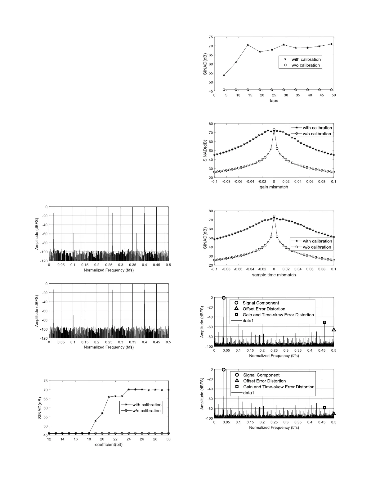
> REPLACE T HIS LINE WIT H YOUR PAPER IDENT IFICATION NUMBE R (DOUBLE -CLICK HERE TO EDI T) < 1 Abstract — This paper describes a ne w all -digital technique fo r calibration of the m ismatches in time-interleaved analog- to -digital converters (TIADCs) to reduce the c ircuit area. The proposed technique gives the first order a pproximation of the gain mismatches an d sample-time mismatche s, and employs firs t order approximation FIR filter banks to calibrate the sa mp led sig nal , which do not need large number of FIR taps. In t he case of a tw o- channel 12 -bit TIADC, the proposed technique improves SINAD of si mulated data fro m 45dB to 69 dB, and improves SINAD of measured data fro m 47dB to 5 3dB, w hile the number of FIR taps is only 30. In the case of slight mis ma tches, 24 -bit FIR coefficient is sufficient to correct 12 -bit signals, w hich makes it easy to implement this technique in hardware. In addition, this te chnique is not limited by the nu mber of sub-ADC channels and can be calculated in parallel i n hardw are, these features enable this technique to be versatile and capable of real-time calibration. Index Ter ms — ADC , time-interleaved , all-digital background calibration , first order approxim ation FIR filter. I. I NTRODUCTIO N N m any fields suc h as wireless i nfrastructure, wideband microwave b ackhauls and measurement equipme nt, hig h speed and high performance anal og - to -di gital convert ers (ADCs) play an essential role. T o meet the requirements of speed and performance, time-interleaved analog - to -digital converter (TIADC) is prop osed to be an effective architectu re, by combining several slo w but accurate sub -ADCs in para llel [1]. However, duo to discre pancies among the sub -ADCs, channel mismatches including offset, gain and sample -time mismatches di stort the sa mpled signal and degrade the SINAD performance of the TIADC significantly [ 2]. Therefore, calibration methods are required to handle the channel mismatches an d restore th e dyn amic performance of sub- ADCs. Recently, a large number of all-digital calibration techniques of TIADC have been proposed. So me use adaptive blind calibration methods [3-5], some use an extra lo w-resolution ADC and a time-varying filter [6], some eliminate mismatches by mea ns of signal s ubtraction between adjac ent c hannels [7 ], and some use Hada mard transform a nd pseudo aliasing sig nal This work was supported by the National Natural Science Foundation of China under G rant 11505182. The au thors are with the State Key Laboratory of Particle Detection and Electronics, University of Science and Technology of Chin a; and De partment [8 -10]. This paper presents a new all -digital background calibration technique for the T IADC, consuming fe w hard ware resources while co mpensating c hannel mismatches. The proposed technique uses FIR filters to complete the calibration function, b ut does not need man y FIR taps. Th us, this method effectively reduce s the amount of co mputation required for t he calibration, while maintaining the dynamic perfor mance of the TIADC. Moreover, this method is not limited by the num ber of TIADC channels a nd can be calculated in parallel in hard ware . II. R ESIDUAL A LIASING D UE T O G AIN A ND S AMPLE - TI ME M ISMATCHES Fig. 1 shows a block diagram of th e M-c hannel TIADC. The sampling rate of th e TIADC is f s =1/ T s , and the sam pling rate of each sub-ADC is f s /M. T he digital o utputs of sub -ADCs are combined to be the output of TIADC. Fig. 2 s hows a simplified block diagra m of the two-channel TIADC. Each sub- ADC sa mples at a lo w frequency of 1/ T 1 , while T 1 =2 T s , and the corresponding discrete -time frequency is 1 T . ) 1 , 0 )( ( m j H m is m-th channel frequency response with gain and sample -time mismatches. T hese chan nel responses are written as ) ( 1 1 ) ( 0 0 1 0 ) 1 ( ) ( ) 1 ( ) ( s s s T t T j T t j e g j H e g j H (1) or M t j s M t j s e g T j H e g T j H ) 1 ( 1 1 0 0 1 0 ) 1 ( ) 2 ( ) 1 ( ) 2 ( ( 2) where m g is the gain mismatch and m t is sa mple-time mismatch in m-th chan nel. Emplo y m o as offset mismatc h, the discrete Fourier transform (DFT) of sampled signal ] [ ˆ n a m of M odern Physics, University of Science and Technolo gy of China, Hefe i 230026, China (Corr esponding author: Z he Cao, e-mail: caoz he@ustc.edu.c n ). A New A ll -Digital Background Calibration T echnique for T ime-Interleaved ADC Using First Order Approximation FIR Filters Jiadong Hu, Z he Cao, Qi An, Lei Zhao, Shu bin Liu I > REPLACE T HIS LINE WIT H YOUR PAPER IDENT IFICATION NUMBE R (DOUBLE -CLICK HERE TO EDI T) < 2 are l s s s k s s s l s s s k s s s l T o T k j T j H T k j T j X T j A l T o T k j T j H T k j T j X T j A ) 2 ( 2 2 2 2 2 2 2 2 2 1 ) ( ˆ ) 2 ( 2 2 2 2 2 2 2 2 2 1 ) ( ˆ 1 1 1 0 0 0 (3) where ) 2 ( s T j X is the DFT of the analo g input signal x ( t ).T he m g , m t and m o can be calculated through a four - parameter sine wave fitti ng method [11] . Normally, o ffset mismatches can be simpl y calibrated by subtracting a certain co nstant, so we ca n assume that the offset mismatches 0 m o in for mula derivation. For the two - channel TIADC, w e assume th at channel 0 is idea l, w hich means 0 0 g , 0 0 t . After ignoring offset mismatc hes and assuming cha nnel 0 to be id eal, the DFT of sampled signal in (3) are simplified to . 2 2 2 2 2 2 2 1 ) ( ˆ ) ( ˆ ) ( ˆ 1 1 0 0 s s k s s s id ea l T k j T j H T k j T j X T j A j A j A (4) The digital output of sub -ADC1 has aliasing signals becaus e of the non-ideality o f ) ( 1 j H . Assuming tha t 1 g and 1 t are much less than 1 in an ac tual TIADC, b y the fir st order approximation, ) ( 1 j H is simplified to 2 1 ) 2 ( ) 2 ( 1 1 1 1 t j g T j H T j H s id ea l s (5) and the DFT of sampled s ignal in (3) are simplified to k t k j g j A j A j A j A k id ea l id ea l 2 2 2 1 ) ( ˆ ) ( ˆ ) ( ˆ ) ( ˆ 1 1 1 1 0 0 (6) where ) , ( , 0 ) , ( , 1 ) ( . (7) The second term and the third term in (6) sh ow residua l aliasing signals due to the gain mismatch and the sample-time m i smatch, respectively. III. P ROPOSED C ALI BR ATION T ECHNIQU E Fig. 3 sho ws the propo sed calibration architecture in t wo- channel TIADC. The key idea is using t he first o rder approximation FIR filter to r educe the channe l mismatch es . After calibration, the final output is appro ximately equal to the ideal output. A. Aliasing Elimination The resid ual aliasing signal i n channel 1 can be eliminate d by means of the follo wing manner ) ( ˆ 2 2 2 1 ) ( ˆ 2 2 2 ) ( ˆ ) ( ˆ ) ( ˆ 1 2 1 1 1 1 1 1 1 1 j A k t k j g j A k t k j j A j A g j A id ea l k id ea l k (8) Suppose first or der approximation FIR filter k DF T n k t k j g j W n g Z n n t n n w 2 2 2 1 0 , 1 , 0 , 2 1 ] [ 1 1 1 1 1 1 1 (9) then ) ( ˆ ) ( ˆ ] [ ˆ ] [ * ] [ ˆ 1 1 1 1 1 1 j A j W j A n a n w n a id ea l DF T id ea l . ( 11 ) B. Propo sed Technique in M -Channel TIA DC For the M-channel TIADC, the DFT of sam pled signal in (3 ) are rewritten as k M t k j g j A j A k m m id ea l m m 2 2 1 ) ( ˆ ) ( ˆ ( 12 ) where m =0, 1, …, ( M -1). T he first order approximation F IR filters are rewritte n as Analog i nput Sub -AD C 0 Sub -AD C 1 Sub -ADC M- 1 ... MUX Digi t al out put Fig. 1. M-channe l TIAD C block diagram. x ( t ) H 0 H 1 a 0 ( t ) z 0 z -1 a 1 ( t ) t = nMT s t = nMT s + + + + Δ o 0 Δ o 1 ˆ x [ n ] a 0 [ n ] a 1 [ n ] ˆ ˆ ↑ M ↑ M Fig. 2. A two- channel TIA DC model. z 0 z -1 a 0 [ n ] a 1 [ n ] ˆ ˆ W 1 ( j ω ) ≈ x ide al [ n ] ˆ ↑ M ↑ M Fig. 3. The propose d calibratio n architecture i n two-channel TIA DC. > REPLACE T HIS LINE WIT H YOUR PAPER IDENT IFICATION NUMBE R (DOUBLE -CLICK HERE TO EDI T) < 3 k m m m DF T m m n m k M t k j g j W n g Z n n M t n n w 2 2 1 0 , 1 , 0 , 1 ] [ 1 ( 13 ) Since m g is far less than 1, the first order ap proximation FIR filters can also be written as k m m m DF T m m n m k M t k j g j W n g Z n n M t n n w 2 2 1 1 0 , 1 1 , 0 , 1 ] [ 1 ( 14 ) then ) ( ˆ ) ( ˆ ] [ ˆ ] [ * ] [ ˆ j A j W j A n a n w n a id ea l m m m DF T id ea l m m m ( 15 ) Fig. 4 shows the o verall architect ure of th e pro posed calibration techniq ue. It can be seen that t he prop osed technique is not limited by t he number of sub-ADC channels. If we assume that one of t he channels is ideal, the n only (M -1) channels need calibratio n. IV. P OL YPHASE I MPLEMENTATI ON Fig. 5 s hows the polyphase im ple mentation structure of th e proposed technique. T he key idea is to treat each sub -ADC as one L-ch annel TIADC. The data of each sub -ADC is br oken up into L portions, after p arallel calibration, th e output data is reorganized into o ne strea m, which is ap proximately equa l to the ideal o utput stream. T his way o f processing ca n speed up the calculation rate by L times in the hardware calibr ation, achieving real-ti me calibration. V. E XPER I MENTAL R ESULTS A. Simula tion Results To verify the efficiency of the propo sed technique, simulations are carried out on a T IADC. Unless ot herwise no ted, the c hannel number i s t wo, signal word len gth is 12bits, the frequency of a nalog input sig nal is 0.0 19f s , the number o f FIR taps is 30, the FIR coefficient word length is 30 bits, offset mismatches 0 m o (m=0, 1), gain mismatch es and sample- time mismatches m g and m t (m=0, 1) ar e 0, 0.01 and 0, 0.01, respectively. Fig. 6 shows outp ut spectru m of the T IADC. The f requency spectra of mismatches are reduced after ca libration, and the SINAD of signal is i mproved from 45 dB to 69 dB. Fig. 7 shows output sp ectrum of a five -channel T IADC. The offset mismatches 0 m o (m=0, 1, 2, 3, 4), gain mismatch es z 0 z -1 z -(M-1 ) a 0 [ n ] a 1 [ n ] a M-1 [ n ] ˆ ˆ ˆ W 0 ( j ω ) W 1 ( j ω ) W M-1 ( j ω ) ≈ x ide al [ n ] ˆ ↑ M ↑ M ↑ M Fig. 4. The propose d calibration architecture in M-chan nel TI ADC. W m0 ( j ω ) W m1 ( j ω ) W m(L -1) ( j ω ) ... a m [ n ] ˆ ≈ a ide al [ n ] ˆ m Fig. 5. Poly phase impleme ntation structure. (a) (b) Fig. 6 . Si ngle frequency signal s pectrum in a t wo-cha nnel TIA DC simulatio n : (a) without and (b) with calibra tion. (a) (b) Fig. 7. Single frequency signal spectr um in a five-channel TIADC simulation : (a) without and (b) with calibra tion. > REPLACE T HIS LINE WIT H YOUR PAPER IDENT IFICATION NUMBE R (DOUBLE -CLICK HERE TO EDI T) < 4 and sample-time mis matches m g and m t (m=0, 1) are 0, 0.01, -0.01, 0 .02, -0.02 and 0, 0 .01, 0.02, -0.01, -0.0 2, respectively. T he frequency spectra of mismatches are r educed after calibration, and the SINAD of signal is i mproved from 36 dB to 69 dB. Fig. 8 shows output spectr um o f the TIA DC when inpu t signal freq uencies are 0.019 f s , 0.133f s , 0.266f s , 0. 399f s , respectively. T he frequency spectra of mismatches are r educed after calibration, which proves the effectiveness of this technique in the wide -band range. Fig. 9 sho ws SINAD versus filter coefficient word length. We can see that 24-bit FIR coefficient is sufficient to correct 12 -bit signals in the case of slight mismatc hes. Fig. 10 shows SINAD versus t he number o f filter taps w h en sample-time mismatches m t (m=0, 1) are 0, 0.02. Fig. 11 shows SINAD versus gain mismatch 1 g when sample-time mismatche s m t (m=0, 1) are 0, 0 and the input signal frequency is 0.46 f s . Fig. 12 shows SINAD versus sa mple- time mismatch 1 t when gain mi smatches m g (m=0, 1) are 0, 0 and the input signal freq uency is 0.19 f s . (a) (b) Fig. 8. Wid eband s ignal spectr um in a tw o-channel TIAD C simulation: (a) without and (b) w ith calibration. Fig. 9. SINA D versus filter coe fficient word le ngth with/without cal ibration. Fig. 10. SI NAD versus filter taps with/without cal ibration. Fig. 11. SI NAD versus gain mismatc h with/witho ut calibration. Fig. 12. SI NAD versus sample- time mismatch with/w ithout calibration. (a) (b) Fig. 13. A two-channel TIADC measured data out put spectrum: (a) without and (b) with calibra tion. > REPLACE T HIS LINE WIT H YOUR PAPER IDENT IFICATION NUMBE R (DOUBLE -CLICK HERE TO EDI T) < 5 B. Measured Data Validatio n In add ition, measured data fro m an actual two -channel TIADC, is carried out calibration. The f s of the T IADC is 1.8GSPS. The sign al word length is 1 2bits, the frequency of analog input signal is 0.039f s , the number of FIR taps is 30, the FIR co efficient word length is 30 bits. Fig. 13(a) shows spectrum b efore calibratio n. After using the calibrati on technique, the spectrum is shown in Fig. 13 (b). The frequenc y spectra of mismatches are reduced after calibration, and the SINAD of signal is i mproved from 47 dB to 53 dB. VI. C ONCLUSION This paper has d escribed a new ar ea-efficient all-digital technique for calibratio n o f the mismatc hes in TIADCs. The proposed technique gives the first order appr oximation of t he gain mismatches and sample -time mismatches, and e mploys first order approximation FIR filter b anks to calibrate the sampled signal, wh ich do not n eed large n umber of FIR taps. In the case of a two -channel 12 -bit TIADC, the prop osed technique improves SIN AD of si mulated data fro m 45dB to 69dB, and i mproves SINAD of measured data fro m 4 7dB to 53dB, while the number of FIR taps is only 30. In the case of slight mismatches, 2 4-bit FIR coeff icient is sufficient to co rrect 12 -bit signals, which m akes it easy to implement this technique in hard ware. In ad dition, this technique is not li mited by the number of sub -ADC channels and can be calculated in p arallel in hardware, these features enable this technique to be versatile and capable of real-time calibration. R EFERENCES [1] Le Duc, Han, et al. "Fully digital feedf orward backgroun d calibration of clock skew s for sub-sampling TI ADCs using the polyphase decomposition." IEEE Transacti ons on Circu its and Systems I: R egular Papers 64.6 ( 2017): 1515-1528. [2] Le Duc, Han, et al. "Hardware implementation of all digital calibrat ion for undersampli ng TIADCs." Circ uits and System s (ISCAS), 201 5 IEEE International S ymposium on . I EEE, 2015. [3] Salee m, Shahzad, and Christia n Vogel . "Adaptive blind ba ckground calibration of poly nomial-represented fre quency response mismatche s in a two- channel time-interle aved ADC." IEEE Trans actions on Circuits and System s I: Regular Papers 58.6 (20 11): 1300-1310. [4] Huang, Steve n, and Bernard C . Levy . "Adaptive blind cal ibration of timing offset a nd gain mismatc h for tw o - ch annel time-interle aved ADCs." IEEE Trans actions on Ci rcuits and Sys tems I: Regul ar Papers 53.6 ( 2006): 1278-1288. [5] Shahmansoori, A rash. "A daptive blind cal ibration of tim ing offsets in a two-channel time-interle aved analog- to -digital converter throug h Lagrange interpol ation." Signal, Im age and Vide o Processin g 9.5 (2015): 1047-10 54. [6] Salee m, Shahzad, and Christia n Vogel . "Adaptive compe nsation of frequency response mismatc hes in high-resol ution time-interle aved ADCs using a lo w-resolution A DC and a time-vary i ng filter." Circuits and Systems (I SCAS), Procee dings of 2010 IEE E Internation al Symposium on . I EEE, 2010. [7] Li, Jing, et al . "A digital timi ng mismatch calibration techn ique in time- interle aved ADCs." IEEE Transac tions on Cir cuits and Systems II : Express Briefs 6 1.7 (2014): 486-49 0. [8] Matsuno, Juny a, et al. "Al l-digital background cal ibration techni que for time-interle aved ADC using pseudo al iasing signal." IEEE Transactions on C ircuits and S ystems I: Regular P apers 60.5 (2013): 1113-1121. [9] Liu, Husheng, a nd Hui Xu. "A calibration metho d for fre quency response mismatc hes in M-channel time-interl eaved analog- to -digital converter s." IEICE Electronics Ex press 13.16 (2016): 20 160668- 20160668. [10] Liu, Husheng, et al. "A calibration me thod for nonli near mismatc hes in M-channel time -interleave d analog- to -digital co nverter s based on Hadamard seque nces." Applied Sci ences 6.11 (2016): 362. [11] IEEE collaboration. "I EEE Standard f or Terminol ogy and Test Met hods for Analog - To -Digital Converters." IEEE Std : 12 41-2000.
Original Paper
Loading high-quality paper...
Comments & Academic Discussion
Loading comments...
Leave a Comment