Joint Radio Resource Allocation, 3D Placement and User Association of Aerial Base Stations in IoT Networks
In this paper, a novel method for joint radio resource allocation (RRA), three-dimensional placement (3DP), and user association of aerial base stations (ABSs) as a main problem in the internet of things (IoT) networks is proposed. In our proposed mo…
Authors: Arman Azizi, Nader Mokari, Mohamad Reza Javan
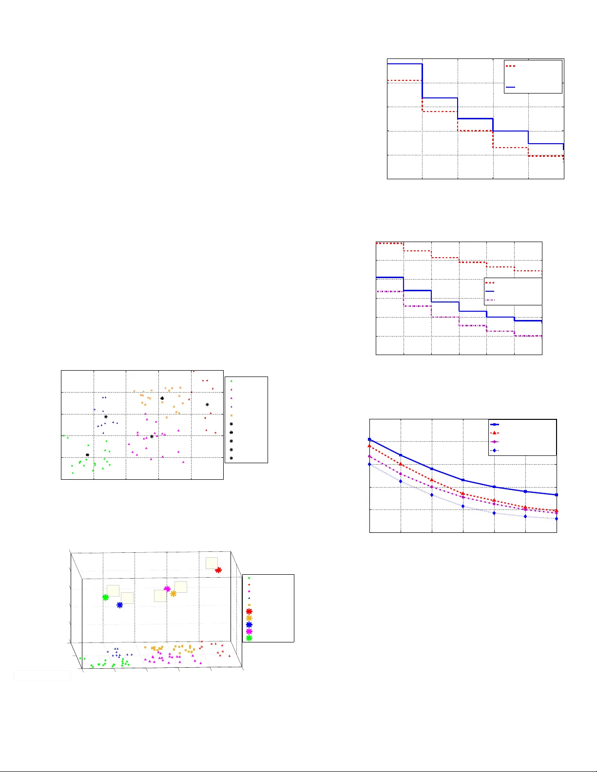
1 Joint Radio Resource Allocation, 3D Placement and User Association of Aerial Base Stations in IoT Networks Arman Azizi, Nader Mokari, Mohamad Reza Jav an Abstract —In this paper , a no vel method f or joint radio r esource allocation (RRA), three-dimensional placement (3DP), and user association of aerial base stations (ABSs) as a main problem in the internet of things (IoT) networks is proposed. In our proposed model, we consider two schemes: a) line of sight (LoS) b) generalized. In the LoS scheme, all the ABSs should see the IoT users as LoS. In the generalized scheme, ABSs can see some of the IoT users as LoS and some of them as NLoS. The main goal of this paper is to minimize the overal transmit power of the IoT users while satisfying some quality of service (QoS) constraints in uplink scenario. T o solve the optimization problems and to conv ert the main problems with high complexity into the subproblems with lower complexity , we decompose them into two subproblems namely 3DP subproblem and joint RRA and user association (JRU) subproblem. The methods which we use to solve our proposed optimization problems are Semi Definite Relaxation (SDR) and Geometric Pr ogramming (GP). Finally , using simulations, we evaluate the performance of the proposed schemes for different values of the network parameters. Index T erms– Aerial Base Station, IoT , Radio Resource Alloca- tion, 3D deployment, User Association, Geometric Programming, Semi Definite Relaxation. I . I N T R O D U C T I O N A. State of the Art 1) Necessity to use U A Vs: The use of unmanned aerial vehicles (U A Vs) in wireless communication networks has receiv ed remarkable attentions recently [1]–[5], [11]–[36]. The use of UA Vs can be useful in some regions which hav e no cellular infrastructures or the areas in which building a cellular infrastructure is very expensi ve. The use of U A Vs as aerial base stations (ABSs) in wireless communication networks mak es lots of adv antages. ABSs can be deployed in higher altitudes compared to the terrestrial base stations. Therefore, they can see ground users with higher chance of line of sight (LoS) links. More over , ABSs can easily move to updated places, and therefore, they can be more flexible than terrestrial base stations in the scenarios where users are mobile [2]. The technical challenges in ABS communication networks can be classified into optimal placement, air to ground (A2G) channel modeling, resource management, energy efficiency , and performance analysis [2]–[4]. In the next generation of wireless communications, networks will require extra dense base stations deployments not only in 2-D area b ut also in 3-D space. Therefore, ABSs can play an important role for wireless cellular networks in ov erloaded cases. Furthermore, ABSs are more robust against en vironmental changes [4]. 2) Necessity to use U A Vs in IoT : IoT can change the ways of wireless communications with all of the devices. An IoT system uses intelligent interfaces for connecting IoT devices to each other at anytime and anywhere which use any network and any service [5]–[8]. More ov er, U A Vs are easy to deploy , capable of reprogramming during run time, capable of measuring an ything anywhere and capable of having high mobility , therefore, they can be chosen to provide many applications, such as service delivery , farming, pollution mitigation, and rescue operations [5], [9], [10]. According to the above definitions, UA Vs are the efficient option to choose for IoT network, and hence, they can play an important role. Furthermore, at the same time, they can provide extra services when they are equipped with some special devices (e.g., cameras, actuators and sensors) [5], [9], [10]. In the other hand, the transmit power of IoT devices are low in comparison with other traditional networks, and hence, IoT de vices can not be able to communicate in long range. More ov er, ABSs can update their locations due to the new locations of IoT devices. Therefore, ABSs can collect IoT data from the IoT devices and transmit it to other devices which are out of transmission range. Accordingly , ABSs can play an important role in IoT networks which have battery-limited devices [11]–[13]. B. Related W orks The Related works to this paper can be classified into the following items: 1) Placement: The authors in [14] maximize the number of users which cov ered by a single ABS by finding the efficient 3D placement for the ABS. In [15], the authors obtain the optimal altitude deployment of a UA V in order to maximize the cov erage. In [16], the authors enhance the cov erage performance in public safety communications by obtaining the optimal deplyment of UA Vs. In [17], the authors use the sigmoid function LoS model to optimize the U A V height in different performance metrics. In [18], the authors design the ABS enabled heterogeneous networks (HetNets) by 3D placements of ABSs as one of the important factors. In [19], the optimal altitude of a single U A V is found to achiev e a required cov erage with minimum transmit po wer . In [20],the authors find the optimal cov erage range and hov ering altitude of U A Vs to minimize the transmit power of them. In [21], the authors propose the next generation heterogeneous network including cooperativ e U A Vs. Accordingly , they find the optimal placement and optimal distribution of U A Vs to 2 optimize the overall network delays. In [22], the authors study on a model which uses density and cost functions to compute the areas with higher demands, and hence, the U A Vs are deployed based on these cost functions. In [23], the locations of ABSs are optimized in order to maximize the network throughput ov er a giv en geographical area. In [24], the authors maximize the fifth percentile capacity of the network by optimizing the locations of the UA Vs. 2) P ower Allocation: In [25], the authors in vestigate a secure wireless network based on physical layer security technique considering U A V as a relay . In order to maximize the secrecy rate, they optimize the transmit po wer of the source and the UA V as a relay while satisfying a sequence of information-causality constraints. These constraints ensure that the relay cannot forward the undecoded data. 3) J oint P ower Allocation and Spectrum Allocation: In [26], the authors present a scenario including cluster heads- U A Vs communications in M2M networks. They propose an efficient scheduling and resource allocation mechanism in order to minimize the transmit power of cluster heads while satisfying rate requirements of M2M de vices. In [27], the au- thors in vestigate a cellular network with multi-layer U A Vs. In order to minimize the packet transmission delay , the resources allocation mechanism proposed. 4) J oint Placement and User Association: In [28], the authors study the optimal deployment of U A Vs and association of static ground users to UA Vs in order to meet the users rate requirements. The work in [29] in vestigates a communication network based on multiple U A Vs in downlink transmissions considering UA V efficient deployment and user association. In [30], the authors study on the U A V netw orks using the sigmoid LoS model in order to characterize the recei ved signal strength. Accordingly , they propose the multi-objectiv e optimization. Furthermore, the UA Vs locations are found as a part of an optimization problem or they are assumed to be known. In [31], the authors present a more comprehensiv e placement and user association problem of a single U A V -BS. In [32], the authors present an IoT network based on UA Vs. They study on deploying the UA Vs efficiently in order to minimize the power consumption of the ground IoT devices by considering the required bit error rate. Furthermore, they present the efficient association of the ground IoT devices to U A Vs. In [33], the authors maximize the users’ quality of experience (QoE) while minimizing the transmit power of the U A Vs. 5) J oint Placement and Spectrum Allocation: In [34], the authors propose a multi-hop D2D network based on U A V in order to dev elop the coverage of network. They show that deploying the U A V in an efficient way increases the data rate assuming the transmit po wer or distance is beyond the threshold. 6) Adaptive Modulation: In [35], the authors inv estigate a scenario in which U A Vs can be used as relays between ground devices and a ground base station. They propose a method in order to control the heading angle of U A Vs considering space-time coding and adaptive modulation, and hence, they optimize the performance of the ground-to-relay links. In [36], the authors maximize the energy ef ficiency in the network in which ground nodes are capable of adaptiv e modulation. Furthermore, they show how mobility pattern of U A Vs can affect on adapti ve modulation. C. Our Contrib ution The main contribution of this paper is to dev elop a nov el approach for inteligently deploying multiple ABSs while min- imizing the overall ABS transmit power needed to satisfy the users data rate in uplink scenario. Furthermore, subcarrier allocation and adaptive modulation are used in this scenario. Our contribution of this paper can be listed as follows: • Joint RRA, 3DP , and User Association: The main factor of ABSs which makes them useful is the ability to mov e, and hence, the location of ABSs is not fixed. Therefore, we should see what is the impact of finding the location of ABSs on RRA and user association. Accordingly , it is necessary to find the radio variables, placement variables, and user association variables in a joint method. T o the best of our knowledge, there is no work which consider the joint RRA, 3DP , and user association. • Comparing A2G channel models: T o the best of our knowledge, there is no work which provide the com- parison between two A2G channel models namely only the LoS scheme and the generalized scheme. Finally , we know which one is better for our IoT Scenario. • Multi ABS, multi IoT users, multi subcarrier system, and adaptiv e modulation: T o the best of our knowledge, there is no work which has all the above items together . In this paper , we show the impact of different modulation orders on ov eral transmit power of IoT users. Furtheremore, we show the impact of ABS numbers on the overal transmit power of the IoT users and the av erage ABS altitude. • Con verting the non-con vex problems into con vex with relaxation methods: W e propose two main problems for our scenario which both of them are non-conv ex and intractable, and hence, we conv ert them into conv ex prob- lems with semidefinite relaxation (SDR) and geometric programming (GP). • Computational Complexity: W e obtain the computational complexity of our proposed schemes. I I . S Y S T E M M O D E L Consider an IoT system consisting of a set I = { 1 , ..., I } including I IoT users deployed within a geographical area. In this system, a set J = { 1 , ..., J } including J ABSs should be deployed to collect the data from the ground devices in the uplink. Furthermore, a set M = { 1 , ..., M } including M modulation orders should be assigned to each user for uplink transmition. The m th modulation order shows that we use 2 m +1 PSK for transmission. The locations of user i and ABS j are, respectiv ely , gi ven by ( ˆ x i ; ˆ y i ) and ( x j ; y j ; h j ) . W e assume that devices transmit in the uplink using orthogonal frequency division multiple access (OFDMA). Note that, we consider a network in which the locations of devices are known to a control center such as a central cloud server . The ground IoT de vices can be mobile (e.g., smart cars) and their data av ailability can be intermittent (e.g., sensors). For A2G 3 d i j A B S j I o T D e v i c e i h j θ i j G r o u n d I o T D e v i c e s Fig. 1. System Model communications, each device can typically have a LoS view tow ards a specific ABS with a given probability . This LoS probability depends on the en vironment, location of the device and the ABS, and the elev ation angle between the device and the ABS [4]. One suitable expression for the LoS probability between ABS j and user i is gi ven by [4]: P r LoS ,ij = 1 1+ α exp( − β ( 180 π θ ij − α )) , ∀ i, j , (1) where α and β are constant values which depend on the carrier frequency and type of environment such as rural, urban, or dense urban, and θ ij is the elev ation angle that is defined as follows: θ ij = 180 π × sin − 1 ( h j d ij ) , ∀ i, j , (2) and d ij is the distance between device i and ABS j given by d ij = q ( x j − ˆ x i ) 2 + ( y j − ˆ y i ) 2 + h 2 j , ∀ i, j . (3) The path loss expressions for LoS and NLoS connections are as follows [4]: L LoS ,ij = 10 n log( 4 π f c d ij c ) + ξ LoS , ∀ i, j , (4) L NLoS ,ij = 10 n log( 4 π f c d ij c ) + ξ NLoS , ∀ i, j , (5) where n is the path loss exponent, L LoS ,ij and L NLoS ,ij are the av erage path loss for LoS and NLoS links, respectiv ely . ξ LoS and ξ NLoS are the average additional loss in addition to the free space propagation loss which depend on the en vironment, c is the speed of light, and f c is the carrier frequency . Finally , the av erage path loss as a function of the ABS altitude and cov erage radius can be written as [15]: L ( x j , y j , h j ) = P r LoS ,ij L LoS ,ij + P r NLoS ,ij L NLoS .ij , (6) T ABLE I S I MU L A T I O N P AR A M E TE R S i IoT user indicator j ABS indicator m Modulation order indicator l Subcarrier indicator ( ˆ x i ; ˆ y i ) 2D location of the i th user ( x j ; y j ; h j ) 3D location of the j th ABS α Constant value depends on en vironment β Constant value depends on en vironment θ ij Elev ation angle of ABS P r LoS ,ij LoS probability between ABS j and user i d ij Distance between device i and ABS j n Path loss exponent L LoS ,ij A verage path loss for LoS link L NLoS ,ij A verage path loss for NLoS link ξ LoS A verage additional loss of LoS link ξ NLoS A verage additional loss of NLoS link c Speed of light f c Carrier frequency L ( x j , y j , h j ) A verage Path loss P r NLoS ,ij NLoS probability between ABS j and user i P recieve imj Receiv ed power from the j th ABS ˆ r ij Symbol rate of the j th U A V to the i th user P transmit imj T ransmit power of IoT user r imj T ransmission bit rate N 0 Noise power spectral density ε Threshold for LoS probability ρ l imj Binary variable for RRA and user association τ i Threshold of transmission rate for each user δ Bit error rate requirement where P r NLoS ,ij is NLoS probability between ABS j and user i . Therefore, we obtain a closed-form for average path loss by substituting (1), (4), and (5) into (6) as follo ws: ¯ L ( x j , y j , h j ) = 10 n log( 4 π f c d ij c )+ P r LoS ,ij ( ξ LoS − ξ NLoS )+ ξ NLoS . (7) For minimum phase shift ke ying (MPSK) modulation, the bit error rate expression is gi ven by [37]: B E R imj = 2 m + 1 Q ( s 2 P receiv e imj ˆ r ij N 0 sin( π 2 m +1 )) , (8) where P receiv e imj is the received power from the j th ABS to the i th user when using the m th modulation order for transmis- sion, ˆ r ij is the symbol rate of the i th user to the j th ABS, N 0 is the noise power spectral density and Q ( . ) is the Q-function. In the next step, we propose the closed-form formulation for transmit po wer of the following schemes. A. The Case with only the LoS By using (4), (8), P transmit imj = P receiv e imj × 10 L LoS,ij 10 , and considering n = 2 , the minimum transmit power of ABS j needed to reach a bit error rate requirement of δ is gi ven by P transmit imj = A m · r imj · d 2 ij , (9) where P transmit imj is the transmit power and r imj = ˆ r ij ( m + 1) is the transmission bit rate from the the i th user to the j th ABS by using the m th modulation order for transmission, 4 respectiv ely . A m is a constant that only changes by the modulation order as follows: A m = ( Q − 1 ( 1 2 δ ( m + 1)) × 1 sin( π 2 m +1 ) ) 2 × 1 ( m + 1) × 1 2 N 0 × ( 4 π f c c ) 2 × 10 ξ LoS 10 , (10) where Q − 1 ( . ) is the inv erse Q-function. In the LoS model, the necessary condition for connecting a device to the U A V is to hav e a LoS probability greater than a threshold ( ε is closed to 1). In other words, P r LoS ( θ ij ) ≥ ε , and hence, θ ij ≥ P r − 1 LoS ( ε ) leading to: d ij ≤ h j sin( P r − 1 LoS ( ε )) , ∀ i, j . (11) Note that (11) guarantees the user i can connect to ABS j if the distance between them is not greater than h j sin( P r − 1 LoS ( ε )) . Our goal is to maximizing the ov eral transmit power of the IoT users in the joint scenario including RRA, 3DP and user association. Accordingly , the objecti ve function is given by: min ρ , x , y , h J X j =1 M X m =1 I X i =1 L X l =1 P transmit imj ρ l imj , (12) where ρ l imj is a binary variable that is one if there is a connection between the i th user and the j th U A V using the m th modulation order in the l th subcarrier , and is zero otherwise. By substituting (9) into (12), our optimization problem can be formulated as: min ρ , x , y , h J X j =1 M X m =1 I X i =1 L X l =1 A m r imj d 2 ij ρ l imj (13a) s.t. ρ l imj ∈ { 0 , 1 } , ∀ i, m, j, l , (13b) J P j =1 M P m =1 L P l =1 r imj ρ l imj ≥ τ i , ∀ i, (13c) ρ l imj + ρ l 0 im 0 j 0 ≤ 1 , ∀ i, j 6 = j 0 , m, l , m 0 , l 0 , (13d) ρ l imj + ρ l im 0 j ≤ 1 , ∀ i, j, l , m 6 = m 0 , (13e) M P m =1 I P i =1 J P j =1 ρ l imj = 1 , ∀ l, (13f) ρ l imj d ij ≤ h j sin( P r − 1 LoS ( ε )) , ∀ i, j, m, l . (13g) Constraint (13c) states that the transmission rate for each user is greater than or equal to a threshold τ i . Constraint (13d) guarantees that only one UA V can be assigned to each user . Constraint (13e) shows that for each ABS, each user and each subcarrier , we can use at most one modulation order . Constraint (13f) shows that the subcarriers are orthogonal in OFDMA. More ov er , it guarantees that for each subcarrier we hav e at most one modulation and one assignment of UA V to user . Constraint (13g) is the necessary condition for connecting a device to a U A V to hav e a LoS probability greater than a threshold. B. Generalized Scheme (J onit NLoS and LoS) In this model, by using (7), (8), P transmit imj = P receiv e imj × 10 ¯ L ( x j ,y j ,h j ) 10 , and considering n = 2 , the minimum transmit power of U A V j needed to reach a bit error rate requirement of δ is gi ven by: P transmit imj = B m × r imj × d 2 ij × 10 P r LoS,ij ( ξ LoS − ξ N LoS ) 10 , (14) where B m is a constant that only changes by the modulation order as follows: B m = ( Q − 1 ( 1 2 δ ( m + 1)) × 1 sin( π 2 m +1 ) ) 2 × 1 ( m + 1) × 1 2 N 0 × ( 4 π f c c ) 2 × 10 ξ N LoS 10 . (15) Therefore, our optimization problem in this case can be demonstrated as follows: min ρ, x , y , h J X j =1 M X m =1 I X i =1 L X l =1 B m r imj ρ l imj d 2 ij × 10 η 1+ α exp( − β ( 180 π sin − 1 ( h j d ij ) − α )) (16a) s.t. (13b) − (13f) , (16b) where η = ( ξ LoS − ξ N LoS ) 10 . I I I . S O L U T I O N A. The Case with only the Line of Sight Our optimization problem is Mixed Integer Nonlinear Pro- gramming (MINLP), noncon vex, and NP-hard. T o solve the resulting optimization problem, it is decomposed into 3DP subproblem and JR U subproblem which are iteratively solved until con ver gence to a local solution. 1) 3DP: The 3DP subproblem can be formulated as Quadratically Constrained Quadratic Program (QCQP) for a fixed vector ρ as follows: min x , y , h J X j =1 M X m =1 I X i =1 L X l =1 A m r imj ρ l imj d 2 ij (17a) s.t. ρ l imj d ij ≤ h j sin( P r − 1 LoS ( ε )) , ∀ i, j ∈ Ω , ∀ m, l , (17b) where Ω = { ( i, j ) | ρ l imj ∈ ρ 0 ∀ m, l } and ρ 0 is an initial matrix for iterative method. Note that by using (3), (17) can be transformed into (18) as follo ws: min x , y , h J X j =1 M X m =1 I X i =1 L X l =1 A m r imj ρ l imj (( x j − ˆ x i ) 2 + ( y j − ˆ y i ) 2 + h 2 j ) (18a) s.t. ρ l imj ( x j − ˆ x i ) 2 + ρ l imj ( y j − ˆ y i ) 2 + ρ l imj h 2 j (1 − 1 sin 2 ( P r − 1 LoS ( ε )) ) ≤ 0 . (18b) 5 As we can see from (18), the optimization problem is a QCQP whose general form is giv en by [39], [40]: min v 1 2 v T W 0 v + Q T 0 v + ˜ r 0 (19a) s.t. 1 2 v T W i v + Q T i v + ˜ r i ≤ 0 , ∀ i. (19b) Giv en (18), we hav e: v = x 1 y 1 h 1 . . x J y J h J T 3 J × 1 , (20) W 0 = Γ 1 0 0 0 0 . 0 0 0 0 . 0 0 0 0 Γ J 3J × 3J , (21) where Γ j is a matrix which can be written as follo ws: Γ j = 2 LM I ω j 0 0 0 2 LM I ω j 0 0 0 2 LM I ω j 3 × 3 , ∀ j ∈ J, (22) and ω j = P i P m P l A m r imj ρ l imj . Also we have: W i = Υ i 1 0 0 0 0 . 0 0 0 0 . 0 0 0 0 Υ iJ 3 J × 3 J , (23) where Υ ij is a matrix that can be written as follo ws: Υ ij = 2 LM ϑ ij 0 0 0 2 LM ϑ ij 0 0 0 2 LM κϑ ij 3 J × 3 J , (24) where κ = 1 − 1 sin 2 ( P r − 1 LoS ( ε )) and ϑ ij = P m P l A m r imj ρ l imj , Furthermore, we have: Q 0 = [ Λ 1 . . Λ J ] T 3 J × 1 , (25) where Λ j is a matrix that can be formulated as follo ws: Λ j = h − 2 LM P i ϑ ij ˆ x i − 2 LM P i ϑ ij ˆ y i 0 i 1 × 3 , Q i = [ Θ i 1 . . Θ iJ ] T 3 J × 1 , Θ ij = − 2 LM ϑ ij ˆ x i − 2 LM ϑ ij ˆ y i 0 1 × 3 , ˜ r 0 = LM J P i γ i ( ˆ x 2 i + ˆ y 2 i ) , γ i = P m P j P l A m r imj ρ l imj , and ˜ r i = LM J ( ˆ x 2 i + ˆ y 2 i ) γ i . Note that W i is not a positi ve semidefinite matrix, and hence, the QCQP problem in (19) is nonconv ex. Therefore, in order to solve the NP-hard problem (19), we should con vert the noncon vex QCQP problem into a semidefinite programming problem by semidefinite programming relaxation (SDR) method. First of all, we should con vert the non-homogeneous QCQP problem into homogeneous QCQP problem. The homogeneous form of problem (19) can be formulated as follo ws [40]: min v ,a 1 2 v T a W 0 Q 0 Q T 0 0 v T a T + ˜ r 0 (26a) s.t. 1 2 v T a W i Q i Q T i 0 v T a T + ˜ r i , (26b) 1 2 v T a 0 0 0 1 v T a T + ˜ r i . (26c) The problem (26) can be formulated as the following equiv a- lent problem: min u,U 1 2 tr ( T 0 U ) + ˜ r 0 (27a) s.t. 1 2 tr ( T i U ) + ˜ r i ≤ 0 , (27b) U = u T u , (27c) u 0 0 0 1 u T = 1 , (27d) where u = v T a 1 × (1+3 J ) , T 0 = W 0 Q 0 Q T 0 0 and T i = W i Q i Q T i 0 . The constraint (27c) is equiv alent to rank( U ) = 1 and U 0 (sho ws the matrix U is semi definite positiv e (SDP)). Furthermore, the constraint (27d) is equiv alent to a 2 = 1 . In the next step, we should con vert the nonconv ex ho- mogeneous QCQP problem (27) into an SDP problem. The constraint rank( U ) = 1 makes the optimization problem (27) noncon vex. Therefore, we should relax the optimization problem (27) by ignoring rank( U ) = 1 . Finally , the conv ex relaxed problem can be written as follows: min U 1 2 tr ( T 0 U ) + ˜ r 0 (28a) s.t. 1 2 tr ( T i U ) + ˜ r i ≤ 0 , (28b) U ≥ 0 , (28c) tr ( H U ) = 1 , (28d) where the constraint (28d) is equiv alent to a 2 = 1 because H = 0 0 0 1 (3 J +1) × (3 J +1) . By solving the problem (28), we reach to optimal U denoted U ∗ . Then, we shoud find u ∗ by Gaussian Randomization Procedure (GRP) [40]. Algorithm 1 Gaussian Randomization Procedure (GRP) s1: Choose a feasible solution U ∗ for the relaxed homogeneous QCQP problem (28). s2: For g = 1 , ..., G generate k g ∼ N (0 , U ∗ ) with zero mean and nonzero cov ariance. s3: Determine g ∗ in argmin n k T g T 0 k g + ˜ r 0 o for the homogeneous QCQP . s4: Output u ∗ = k ∗ g for the homogeneous QCQP . As we know that u = v T a , we can find v ∗ . Therefore, the relaxed con ve x-3DP problem can be solved by some existing optimization tools such as CVX. 6 2) J onit RRA and User Association (JRU): The JR U sub- problem can be formulated as Binary Linear Programming (BLP) for fixed x, y , h as follows: min ρ J X j =1 M X m =1 I X i =1 L X l =1 A m r imj ρ l imj d 2 ij (29a) s.t. (13b) − (13g) . (29b) Therefore, JR U subproblem as a Binary Linear Programming can be solved by some existing optimization tools such as NO- MAD. Finally , the main problem can be solved by Algorithm 2. where t is the iteration number, T is the upper bound for Algorithm 2 Iterative procedure of obtaining optimal solution s1: Initialize ρ from the feasible set. s2: Calculate x ∗ , y ∗ , h ∗ from 3DP subproblem for fixed ρ . s3: Calculate obj1 and obj2 from (17a) and (29a), respectively . s4: f or t = 1 to T do s4: While | obj 1 − obj 2 | ≥ σ or t < T calculate ρ ∗ from the JR U subproblem for fixed x, y , h and x ∗ , y ∗ , h ∗ from 3DP subproblem for fixed ρ . s4: Set t = t + 1 s4: end for s5: ( ρ ∗ , x ∗ , y ∗ , h ∗ ) is the optimal solution. the iteration number , σ is a number close to zero, obj1 and obj2 are the objectiv es of 3D placement subproblem and joint RRA and user association subproblem, respectiv ely . B. Generalized Model Our optimization problem in the general case is also a MINP which is nonconv ex and NP-hard. Therefore, to solve the problem, we decompose it into 3DP subproblem and JR U subproblem. 1) 3DP: The 3DP subproblem can be formulated as ge- ometric programming problem [38], [39] for a fixed ρ as follows: min x , y , h J X j =1 M X m =1 I X i =1 L X l =1 B m r imj ρ l imj d 2 ij × 10 η 1+ α exp( − β ( 180 π sin − 1 ( h j d ij ) − α )) (30) The 3DP subproblem can be transformed into the following problem: min x , y , h , t 0 , t 1 , f 0 J X j =1 M X m =1 I X i =1 L X l =1 B m r imj ρ l imj ( t 2 0 ,ij + t 2 1 ,ij + h 2 j ) × 10 η 1+ α exp( − β ( 180 π sin − 1 ( h j d ij ) − α )) (31a) s.t. 1 2 x j ( ˆ x i ) − 1 2 t − 1 2 0 ,ij = 1 , ∀ i, j ∈ Ω , (31b) 1 2 y j ( ˆ y i ) − 1 2 t − 1 2 1 ,ij = 1 , ∀ i, j ∈ Ω , (31c) f − 2 0 ,ij t 2 0 ,ij h − 2 j + f − 2 0 ,ij t 2 1 ,ij h − 2 j + f − 2 0 ,ij 6 1 , ∀ i, j ∈ Ω , (31d) where d 2 ij in (30) is transformed into t 2 0 ,ij + t 2 1 ,ij + h 2 j in (31a) as expalined before in the LoS scheme. (31d) is the posynomial form of d ij h j 6 f 0 ,ij . Proposition 1 : f can be approximated by a monomial if and only if F ( y ) = log f ( e y ) can be approximated by an affine function. Furthuremore, f can be approximated by a generalized posynomial if and only if F can be approximated by a conv ex function [38]. By Proposition 1, we can show that the function sin − 1 ( 1 f 0 ,ij ) can be approximated by a monomial if the function log(sin − 1 (exp( − f 0 ,ij ))) is affine. It can be shown that this function is af fine for f 0 ,ij > 0 . 2 and this condition always is established because 1 6 d ij h j 6 f 0 ,ij . Therefore, we have sin − 1 ( 1 f 0 ,ij ) ≈ µ 2 f ω 2 0 ,ij . By substituting sin − 1 ( 1 f 0 ,ij ) ≈ µ 2 f ω 2 0 ,ij into (31a) and using the follo wing approximations [38]: exp( 180 π β µ 2 f ω 2 0 ,ij ) ≈ (1 + 180 π β µ 2 f ω 2 0 ,ij ψ ) ψ , (32) 10 ηµ 3 f ψ − ω 3 1 ,ij ≈ (1 + η µ 3 f ψ − ω 3 1 ,ij log 10 e φ ) φ , (33) f ψ 1 ,ij + α exp( αβ ) ≈ µ 3 f ω 3 1 ,ij , (34) where (32) and (33) are approximated for large amount of ψ and φ , respectively , our 3DP subproblem can be demonstrated as a GP problem. Furthermore, (34) shows monomial approx- imation for f ψ 1 ,ij + α exp( αβ ) . Finaly , the 3DP subproblem in the form of GP can be obtained as follows: min x , y , h , t 0 , t 1 , f 0 , f 1 , f 2 J X j =1 M X m =1 I X i =1 L X l =1 B m r imj ρ l imj ( t 2 0 ,ij + t 2 1 ,ij + h 2 j ) × f φ 2 ,ij (35a) s.t. (31b) , (31c) , (31d) , (35b) f − 1 1 ,ij + 180 π β µ 2 f ω 2 0 ,ij ψ − 1 f − 1 1 ,ij 6 1 , ∀ i, j ∈ Ω , (35c) f − 1 2 ,ij + η µ 3 f ψ − ω 3 1 ,ij log 10 e φ f − 1 2 ,ij 6 1 , ∀ i, j ∈ Ω , (35d) where (35c) and (35d) come from the exponential terms that approximated for large amount of ψ and φ in (32) and (33), respectiv ely . Therefore, the 3DP subproblem as a geometric programming can be solved by some existing optimization tools such as CVX. 7 2) JR U: The JRU subproblem can be formulated as Binary Linear Programming (BLP) for fixed x, y , h as follows: min ρ J X j =1 M X m =1 I X i =1 L X l =1 A m r imj ρ l imj d 2 ij × 10 η 1+ α exp( − β ( 180 π sin − 1 ( h j d ij ) − α )) (36a) s.t. (13b) − (13f) , (36b) Therefore, the JR U subproblem as a BLP can be solved by some existing optimization tools such as NOMAD. Finally , the main problem can be solved by an iterativ e algorithm similar to Algorithm 2. I V . C O M P U TA T I O NA L C O M P L E X I T Y Here, we discuss the computational complexity of our proposed optimization problems, namely , LoS scheme and generalized scheme. Moreover , each of the proposed methods is decomposed into two subproblems namely JR U and 3DP . Therefore, we should compute the complexity of each of the subproblems in both of the proposed methods. In the 3DP subproblem of LoS scheme, we use SDR in order to relax the 3DP subproblem, and hence, its computational complexity can be formulated as follo ws: max { 3 J + 1 , I + 1 } 3 (3 J + 1) 0 . 5 log( 1 / ˜ µ ) , (37) where ˜ µ > 0 is used for the given accuracy solution of interior point method (IPM). SDR is a computationally ef- ficient approximation approach to QCQP in the sense that its complexity is polynomial in the problem size and the number of constraints. The computational complexity of JR U subproblem in the LoS scheme can be written as follows: log( 4 I M J L + I + L ˜ t ˜ µ ) log( ˜ ξ ) , (38) where ˜ µ is used for the accuracy updating of interior point method (IPM), ˜ ξ is the stopping criterion for IPM, and ˜ t is the initial point for approximating the accuracy of IPM. The computational complexity formulation of JRU subprob- lem in the generalized scheme is the same as (38). Further- more, the computational complexity of 3DP subproblem in the generalized scheme can be written as follows: log( 5 I J ˜ t ˜ µ ) log( ˜ ξ ) . (39) The computational complexity of the proposed problems can be listed in the T able II as follo ws: V . S I M U L AT I O N R E S U LT S In our simulations, the IoT users are deployed in an area of size 1 km × 1 km . W e consider this scenario in an urban en vironment with α = 9 . 61 and β = 0 . 16 at 2.1 GHz carrier frequency . T able III defines the simulation parameters. Note that we reach to all the results after a large number of independent runs. T ABLE II C O MP U TA T I O NA L C O M P LE X I TY Kind of Problem Computational Complexity 3DP Subproblem of LoS scheme max { 3 J + 1 , I + 1 } 3 × (3 J + 1) 0 . 5 log( 1 ˜ µ ) JR U Subproblem of LoS Scheme log( 4 I M J L + I + L ˜ t ˜ µ ) log( ˜ ξ ) 3DP Subproblem of Generalized Scheme log( 5 I J ˜ t ˜ µ ) log( ˜ ξ ) JR U Subproblem of Generalized Scheme log( 4 I M J L + I + L ˜ t ˜ µ ) log( ˜ ξ ) T ABLE III S I MU L A T I O N P AR A M E TE R S f c carrier frequency 2.1GHz δ bit error rate 10 − 8 N 0 noise power spectral density -170 dBm ξ LoS aditional loss for LoS 1.6dB ξ NLoS aditional loss for NLoS 23dB n path loss exponent 2 α constant value for P LoS 9.61 β constant value for P LoS 0.16 Fig. 2 indicates that which user is connected to which ABS and shows the efficient locations of ABSs should be deployed. In this figure, we have 5 ABSs to support 80 IoT users. Note that, each ABS can be allocated to at most 25 IoT users because of resource block limitation. Therefore, the maximum size of the IoT user clusters is 25. It is obvious that the location of IoT users af fects on the number of users per cluster and also the ef ficient locations of the ABSs. Note that, the minimum and maximum IoT user cluster sizes are 10 and 20, respecti vely . Fig. 3 shows the 3-D view of ABSs deployment, and hence, we can see that ABSs altitude affects on the number of IoT users to support. Fig. 4 sho ws the average ABS altitude versus the number of the ABSs for two different channel models which we use in our system model as LoS scheme and generalized scheme. Note that, by increasing the number of ABSs, the av erage ABS altitude decreases. By increasing the number of ABSs, ov erlapping between the coverage regions of the ABSs increases. Therefor , the cov erage radius of ABSs must be decreased by reducing their height. More ov er, in the generalized scheme the ABSs can see the users in dense area as LoS and see other users as NloS. Therefore, the average ABS altitude reduces in generalized scheme in comparison with the LoS scheme. Due to the fact that ABSs in higher altitude need more transmit po wer, and hence, the overall transmit power of IoT users in generalized scheme is lower than the ov erall transmit po wer in LoS scheme as sho wn in Fig. 5. Fig. 5 shows the overal transmit power of IoT users versus the number of ABSs. In this figure, the performance of the proposed methods is compared with the fixed ABSs case which considers that the locations of ABSs are known. In the fixed ABSs case, assuming a uniform distribution of IoT users, we fix the location of ABSs at an altitude of 550 m, and then, we assign each IoT user to the nearest ABS. Therefore, in the fixed ABSs case we have only RRA optimization problem. In 8 the next step, we can see that the maximum size of each cluster decreases as the number of ABSs increases. Furthermore, we can see that the generalized scheme can be more efficient than the LoS scheme because the average altitude of ABSs decreases in the generalized scheme in comparison with the LoS method. Note that, the proposed generalized model does not spoil the LoS ability of ABSs. For example, consider a number of users that most of them are densified in an area but a few numbers are far from the majority . If we use the LoS scheme for deployment of ABSs, we must deploy them in high altitudes that they can see all the users with LoS, But we can wai ver the minority and deploy the ABSs in a way that they can only see the majority of IoT users as LoS. Not only this assumption does not spoil the LoS ability of ABSs, but also it can make our method more efficient in practical cases. As expected, increasing the number of ABSs reduces the ov eral transmit power of IoT users. Fig. 6 shows the overal transmit power of the IoT users versus the number of the ABSs. W e can see, using two mod- ulation order (QPSK+8PSK) is more ef ficient in comparison with (QPSK). Using different modulation orders makes the ABSs more flexible than before in order to choose the best option for connection, and hence, the Overal transmit power of the IoT users decreases in comparison with the case using one modulation order . As expected, the total transmit power of the generalized model is lower than the LoS method. 0 200 400 600 800 1000 0 200 400 600 800 1000 X−coordinate (m) Y−coordinate (m) Cluster 1 Cluster 2 Cluster 3 Cluster 4 Cluster 5 ABS ABS ABS ABS ABS Fig. 2. User association and 2D placement of ABSs considering the case with only the LoS 0 200 400 600 800 1000 0 500 1000 0 100 200 300 400 500 X: 900 Y: 685.4 Z: 442.7 X: 623.5 Y: 742.7 Z: 305 X: 559.6 Y: 392.7 Z: 381.6 X−coordinate (m) X: 276.7 Y: 573.3 Z: 269.7 X: 163.3 Y: 223.5 Z: 362.6 Y−coordinate (m) Z−coordinate (m) Cluster 1 Cluster 2 Cluster 3 Cluster 4 Cluster 5 ABS for cluster 2 ABS for cluster 5 ABS for cluster 4 ABS for cluster 3 ABS for cluster 1 Fig. 3. User association and 3D placement of ABSs considering the case with only the LoS 3 4 5 6 7 8 100 200 300 400 500 600 ABS number Average ABS ALtitude Generalized LoS Fig. 4. The average ABS altitude vs. the number of the ABSs in two cases: LoS and generalized 4 5 6 7 8 9 10 20 40 60 80 100 120 140 ABS number Overall transmit power (mW) Fixed ABS case LoS Generalized Fig. 5. The overall transmit po wer of IoT users vs. the number of the ABSs in three cases: fixed ABS case, LoS and generalized 4 5 6 7 8 9 10 20 40 60 80 100 120 ABS number Overall transmit power (mw) M=1 (LoS) M=2 (LoS) M=1 (Generalized) M=2 (Generalized) Fig. 6. The total transmit power of IoT users vs. the number of the ABSs in two schemes considering different modulation orders V I . C O N C L U S I O N In this paper, we in vestigated the joint RRA, 3DP , and user association for ABSs in IoT networks considering adaptiv e modulation. Note that, we considered two schemes with dif- ferent channel models, namely , generalized scheme and LoS scheme. In our proposed methods, we found the efficient 3D locations of ABSs in order to minimize the overal transmit power of the IoT users satisfying some existing QoS Con- straint. The results showed that by carefully clustering the IoT users and deploying the ABSs, the overal transmit power of the IoT users significantly decreases in comparison with 9 the fixed ABSs case. More over , the generalized scheme can be more efficient in some practical cases in comparison with the LoS scheme. As expected, by increasing the number of ABSs, overal transmit power of users decreases. Finally , we showed that by increasing the ABSs number , the average ABS altitude decreases, and hence, it is obvious that there is a trade off between number of ABSs and average ABS altitude. Note that, we use OFDMA technology for our proposed scenario. Accordingly , we want to study on some existing multiple access technologies in next generation such as sparse code multiple access (SCMA) and po wer domain non orthogonal multiple access (PD-NOMA) in order to use in our proposed scenario as future work. More over , we can e xtend our proposed system model into multi tier heterogeneouse Base Stations which can make our model valid for next generation scenarios. R E F E R E N C E S [1] M. Mozaffari, W . Saad, M. Bennis, and M. Debbah, ”Unmanned aerial vehicle with underlaid de vice-to-device communications: Performance and tradeoffs, ” IEEE T ransactions on W ireless Communications , vol. 15, no. 6, pp. 3949-3963, 2016. [2] I. Bekmezci, O. K. Sahingoz, and S. T emel, ”Flying ad-hoc networks (F ANETs): A survey , ” Ad Hoc Networks , vol. 11, no. 3, pp. 1254-1270, 2013. [3] D. Orfanus, E. P . de Freitas, and F . Eliassen, ”Self-organization as a supporting paradigm for military UA V relay networks, ” IEEE Communi- cations Letters , vol. 20, no. 4, pp. 804-807, 2016. [4] A. Hourani, S. Kandeepan, and A. Jamalipour , ”Modeling air-to-ground path loss for low altitude platforms in urban en vironments, ” in Pr oc. of Global Communications Conference (GLOBECOM) , Austin, TX, USA, 8-12 Dec. 2014, pp. 2898-2904. [5] N. H. Motlagh, T . T aleb, and O. Arouk, ”Low-altitude unmanned aerial vehicles-based internet of things services: Comprehensive survey and future perspectives, ” IEEE Internet of Things Journal , vol. 3, no. 6, pp. 899-922, 2016. [6] M. Razzaque, M. Miloje vic, A. Palade and S. Clarke, ”Middleware for internet of things: a survey , ” IEEE Internet of Things Journal , vol. 3, no. 1, pp. 70-95, 2016. [7] V . Angelakis, I. A vgouleas, N. Pappas, E. Fitzgerald and D. Y uan, ”Allocation of heterogeneous resources of an IoT device to flexible services, ” IEEE Internet of Things Journal , vol. 3, no. 5, pp. 691-700, 2016. [8] A. Ngu, M. Gutierrez, V . Metsis, S. Nepal and Q. Sheng, ”IoT middle- ware: A survey on issues and enabling technologies, ” IEEE Internet of Things Journal , vol. 4, no. 1, pp. 1-20, 2017. [9] C. Y in, Z. Xiao, X. Cao, X. Xi, P . Y ang and D. W u, ”Offline and Online Search: UA V Multi-Objective Path Planning under Dynamic Urban Environment, ” IEEE Internet of Things Journal , 2017. [10] N. Motlagh, M. Bagaa and T . T aleb, ”U A V -based iot platform: A cro wd surveillance use case, ” IEEE Communications Magazine , vol. 55, no. 2, pp. 128-134, 2017. [11] Z. Dawy , W . Saad, A. Ghosh, J. G. Andre ws, and E. Y aacoub, ”T oward massiv e machine type cellular communications, ” IEEE W ireless Commu- nications , vol. 24, no. 1 ,pp. 120-128, 2017. [12] S.Y . Lien, K.C. Chen, and Y . Lin, ”T oward ubiquitous massiv e accesses in 3GPP machine-to-machine communications, ” IEEE Communications Magazine , vol. 49, no. 4, 2011. [13] H. S. Dhillon, H. Huang, and H. V iswanathan, ”W ide-area wireless com- munication challenges for the Internet of Things, ” IEEE Communications Magazine , vol. 55, no. 2, pp. 168–174, 2017. [14] R. Y aliniz, A. El-Keyi, and H. Y anikomeroglu, ”Efficient 3-D placement of an aerial base station in next generation cellular networks, ” in Pr oc. of Communications (ICC) , Kuala Lumpur, Malaysia, 22-27 May 2016, pp. 1-5. [15] A. Hourani, K. Sithamparanathan, and S. Lardner, ”Optimal LAP altitude for maximum coverage, ” IEEE W ireless Communications Letters , vol. 3, no. 6, pp. 569-572, 2014. [16] J. K osmerl and A. V ilhar, ”Base stations placement optimization in wireless networks for emergency communications, ” in Pr oc. of Commu- nications (ICC) , Sydney , NSW , Australia, 10-14 June 2014, pp. 200-205. [17] A. M. Hayajneh et al, ”Optimal Dimensioning and Performance Anal- ysis of Drone-Based W ireless Communications, ” in Pr oc. of Globecom W orkshops (GC Wkshps) , W ashington, DC, USA, 4-8 Dec. 2016, pp. 1-6. [18] M. Alzenad, M. Z. Shakir, H. Y anikomeroglu, and M. Alouini, ”FSO- based vertical backhaul/fronthaul framework for 5G+ wireless networks, ” arXiv preprint arXiv:1607.01472 , 2016. [19] M. Mozaf fari, W . Saad, M. Bennis, and M. Debbah, ”Drone small cells in the clouds: Design, deployment and performance analysis, ” in Pr oc. of Global Communications Confer ence (GLOBECOM) , San Diego, CA, USA, 6-10 Dec. 2015, pp. 1-6. [20] M. Mozaffari, W . Saad, M. Bennis, and M. Debbah, ”Efficient deploy- ment of multiple unmanned aerial vehicles for optimal wireless cov erage, ” IEEE Communications Letters , vol. 20, no. 8, pp. 1647-1650, 2016. [21] V . Sharma, R. Sabatini and S. Ramasamy , ”U A Vs assisted delay op- timization in heterogeneous wireless networks, ” IEEE Communications Letters , vol. 20, no. 12, pp. 2526-2529, 2016. [22] V . Sharma, M. Bennis and R. Kumar , ”UA V -assisted heterogeneous networks for capacity enhancement, ” IEEE Communications Letters , vol. 20, no. 6, pp. 1207-1210, 2016. [23] A. Merwaday , A. T uncer, A. Kumbhar and I. Guvenc, ”Improved throughput coverage in natural disasters: Unmanned aerial base stations for public-safety communications, ” IEEE V ehicular T echnology Maga- zine , vol. 11, no. 4, pp. 53-60, 2016. [24] A. Merwaday and I. Guvenc, ”U A V assisted heterogeneous networks for public safety communications, ” in Proc. of W ireless Communications and Networking Conference W orkshops (WCNCW) , New Orleans, LA, USA, 9-12 March 2015, pp. 329-334. [25] Q. W ang, Z. Chen, W . Mei, J. Fang, ”Improving physical layer security using UA V -enabled mobile relaying, ” IEEE Wir eless Communications Letters , 2017. [26] M. Soorki, M. Mozaf fari, W . Saad, M. Manshaei and H. Saidi, ”Resource allocation for machine-to-machine communications with unmanned aerial vehicles, ” in Proc. of Globecom W orkshops (GC Wkshps) , W ashington, DC, USA, 4-8 Dec. 2016, pp. 1-6. [27] J. Li and Y . Han, ”Optimal resource allocation for packet delay mini- mization in multi-layer UA V networks, ” IEEE Communications Letters , vol. 21, no. 3, pp. 580-583, 2017. [28] Z. Han, A. L. Swindlehurst, and K. Liu, ”Optimization of MANET connectivity via smart deployment/mov ement of unmanned air v ehicles, ” IEEE T ransactions on V ehicular T echnology , vol. 58, no. 7, pp. 3533- 3546, 2009. [29] M. Mozaf fari, W . Saad, M. Bennis, and M. Debbah, ”Optimal transport theory for po wer-efficient deployment of unmanned aerial vehicles, ” in Pr oc. of Communications (ICC) , Kuala Lumpur , Malaysia, 22-27 May 2016, pp. 1-6. [30] A. Fotouhi, M. Ding, and M. Hassan, ”Dynamic base station reposition- ing to improve performance of drone small cells, ” in Proc. of Globecom W orkshops (GC Wkshps) , W ashington, DC, USA, 4-8 Dec. 2016, pp. 1-6. [31] E. Kalantari, M. Z. Shakir, H. Y anikomeroglu, and A. Y ongacoglu, ”Backhaul-aware robust 3D drone placement in 5G+ wireless networks, ” arXiv preprint arXiv:1702.08395 , 2017. [32] M. Mozaff ari, W . Saad, M. Bennis, and M. Debbah, ”Mobile Internet of Things: Can U A Vs provide an energy-ef ficient mobile architecture?, ” in Proc. of Global Communications Confer ence (GLOBECOM) , W ash- ington, DC, USA, 4-8 Dec. 2016 , pp. 1-6. [33] M. Chen and M. Mozaffari, W . Saad, C. Y in, M. Debbah, C. Hong ”Caching in the sky: Proactive deployment of cache-enabled unmanned aerial vehicles for optimized quality-of-experience, ” IEEE Journal on Selected Areas in Communications , vol. 35, no.5, pp. 1046-1061, 2017. [34] X. Li, D. Guo, and H. Y in, G. W ei ”Drone-assisted public safety wireless broadband network, ” in Proc. of W ireless Communications and Networking Conference W orkshops (WCNCW) , New Orleans, LA, USA, 9-12 March 2015, pp. 323-328. [35] P . Zhan, K. Y u and L. Swindlehurst ”Wireless relay communications with unmanned aerial vehicles: Performance and optimization, ” IEEE T ransactions on Aerospace and Electronic Systems , vol. 47, no.3, pp. 2068-2085, 2011. [36] A. Abdulla, Z. Fadlullah, H. Nishiyama, N. Kato, F . Ono, R. Miura ”T oward fair maximization of energy efficiency in multiple U AS-aided networks: A game-theoretic methodology , ” IEEE Tr ansactions on W ir e- less Communications , vol. 14, no. 1, pp. 305-316, 2015. [37] A. Goldsmith, W ireless Communications, Cambridge university press, 2005. [38] S. Boyd, S. Kim, L. V andenberghe and A. Hassibi, ”A tutorial on geometric programming, ” Optimization and engineering, Springer , vol. 8, no. 1, 2007. 10 [39] S. Boyd and L. V andenberghe, ”A tutorial on geometric programming, ” Cambridge university press , 2004. [40] Z. Luo, W . Ma, A. So, Y . Y e and S. Zhang ”Semidefinite relaxation of quadratic optimization problems, ” IEEE Signal Processing Magazine , vol. 27, no. 3, pp. 20-34, 2010.
Original Paper
Loading high-quality paper...
Comments & Academic Discussion
Loading comments...
Leave a Comment