Efficient Algorithms and Routing Protocols for Handling Transient Single Node Failures
Single node failures represent more than 85% of all node failures in the today's large communication networks such as the Internet. Also, these node failures are usually transient. Consequently, having the routing paths globally recomputed does not p…
Authors: Amit M Bhosle, Teofilo F Gonzalez
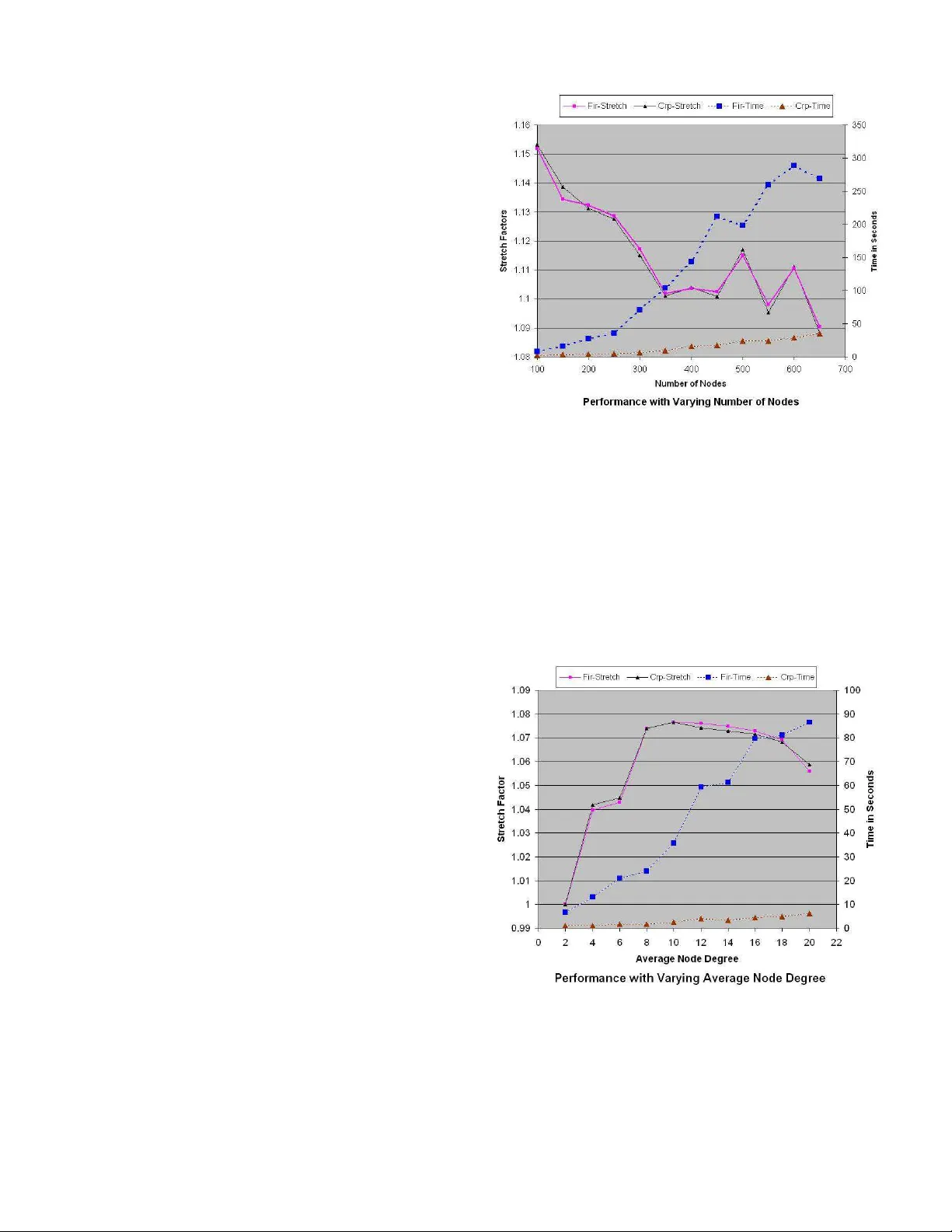
EFFICIENT ALGORITHMS AND R OUTING PR O T OCOLS FOR HANDLING TRANSIENT SINGLE NODE F AILURES Amit M. Bhosle ∗ and T eofilo F . Gonzalez Departmen t of C o mputer Science University of California Santa Barbara, CA 9310 6 { bhosle,teo } @cs.ucsb.edu Abstract Single node failures r epr esent more than 85% of all node failur es[7] in the today’s lar ge communica tion net- works such as the Internet. Also, these node failures ar e usually tran sient . Consequently , having the r outing path s globally r ecomputed does not pay off si n ce the failed nodes r ecover fa irly q uickly , a nd the r ecompu ted r outin g path s need to be discar ded. Instead, we develop algorithms a nd pr otocols fo r d ealing with such transient sing le nod e fail- ur es by suppr essing the failur e (instead o f advertising it acr oss th e network), and r outing messages to the destina- tion via alternate pa ths that do n ot use the failed no de. W e compare our solu tion to that of [11 ], which also discusses such a proactive r ecovery scheme for hand ling transient node failures. W e show that o ur algo rithms a r e fa ster by an or d er of magnitude while our p aths a r e equally good . W e show via simulation r esults that our paths ar e usually within 15 % of the o ptimal for randomly generated graph with 100-1 000 nodes. KEY WORDS: Network Pr otoc ols, Node F ailur e R ecov- ery , T ransient Node F ailur es, Alternate P ath Routing. 1 Intr oduction Let G = ( V , E ) be an ed ge weighted grap h that represents a computer network, whe re the w eight (positive real n um- ber), d enoted by cost ( e ) , of the edges r epresents th e cost (time) requir ed to transmit a packet th rough the edge (link) . The numbe r of vertices ( | V | ) is n a nd the num ber of edges ( | E | ) is m . It is well known th at a shortest path s tree of a node s , T s , specifies the fastest way o f transmittin g a mes- sage to node s origin ating at any given node in the grap h under the assumption that messages can be transmitted at the specified costs. Und er normal operation the routes are the fastest, but wh en the sy stem carries hea v y traffic on some links these routes might not be the best routes. These trees can be constructed (in p olyno mial time) by finding a shortest path between every pair of nodes. In this p aper we consider th e case when the nodes in the n etwork are ∗ Currentl y at Amazon . com, 1200 12 th A ve. S., Seattle , W A - 98144 susceptible to transient faults. These are sporad ic faults of at most one n ode 1 at a time that last for a relativ ely short period of time. This ty pe of situation h as been studied in the past [11] because it represen ts m ost of the n ode fail- ures occurr ing in ne tworks. Sin gle node failures represent more than 8 5% of all n ode failures [7]. Also, these node failures are usually transient , with 46% lasting less than a minute, and 86 % lasting less than 10 minu tes [7]. Because nodes fail for relati ve short periods of time, propagating in- formation abou t th e failure thro ugho ut the n etwork is not recommen ded. In this pa per we consider the case where the net- work is bicon nected ( 2- node-c onnected ), meaning that the deletion of a single node does not disconn ect the network. Based o n our previous assumptions abo ut failures, a mes- sage origin ating at node x with destination s will be sen t along the path spe cified by T s until it reaches node s o r a node (other than s ) that failed. In the latter case, we need to use a rec overy path to s from that point. Since we assum e single no de faults and the graph is biconnected, such a path always e x ists. W e call this pr oblem of finding the recovery paths the Sing le Nod e F ailure Recovery (SNFR) pr oblem. It is impo rtant to recognize that the r ecovery path depen ds heavily on the protocol being deployed in the system. Later on we discuss our (simple) routing protocol. 1.1 Preliminaries Our commun ication n etwork is m odeled by an edg e- weighted biconn ected undirected graph G = ( V , E ) , with n = | V | and m = | E | . Each edge e ∈ E has an associated cost (weig ht), deno ted by cost ( e ) , which is a non-negative real number . p G ( s, t ) denotes a shortest path between s and t in graph G and d G ( s, t ) to denote its cost (weight). A shortest p ath tr ee T s for a no de s is a collection of n − 1 edge s { e 1 , e 2 , . . . , e n − 1 } of G which fo rm a spa nning tree of G such tha t the path from node v to s in T s is a shortest path f rom v to s in G . W e say that T s is rooted at node s . With respect to this root we define the set of nodes that are th e childr en of each n ode x as f ollows. In T s we say that every node y that is adjacent to x such th at x is on 1 The nodes are single- or multi- processor compute rs 1 the path in T s from y to s , is a child o f x . For each nod e x in the shortest p aths tree, k x denotes the number of ch ildren of x in the tree, and C x = { x 1 , x 2 , . . . x k x } d enotes this set of children of th e node x . Also, x is said to be the parent of each x i ∈ C x in the tree T s . With respect to s , the paren t node, p , of a node c is sometimes referred to as the primary neighbo r or primary r outer of c , while c is referred to as an upstr eam neig hbor o r upstr eam r o uter of p . The children of a particula r node are said to be siblings of eac h o ther . V x ( T ) d enotes the set o f nodes in th e subtree of x in the tree T an d E x ⊆ E denotes th e set of all edges incid ent on the nod e x in the graph G . W e use nextH op ( x, y ) to denote the next node fro m x o n the sho rtest pa th tree from x to y . Note that by definition, nextH op ( x, y ) is the parent of x in T y . Finally , we use ρ x to denote the escape edge in G ( E ) \T s that the node x uses to recover from the failure of its paren t. As we discuss later, ha vin g the infor mation of a single escap e ed ge ρ x for each node x ∈ G ( V ) and x 6 = s is sufficient to con struct the entire altern ate path fo r any node to recover from the failur e of its par ent, e ven though the path may actually contain multiple non-tr ee edges. 1.2 Related W ork One popular approach of tackling the issues related to tran- sient f ailu res of network elements is that of using pr oactive r ecovery schemes . T hese schemes typ ically work by pre- computin g alternate paths at the network setup time for the failure scenario s, and then using these alternate paths to re- route the traf fic wh en the failure actually occurs. Also, the informa tion o f the failure is sup pressed in the hope that it is a transient failure. T he lo cal rer outing based solutions propo sed in [1, 6, 9, 10, 11] fall into this category . Refs. [ 8, 1 1] present protoco ls based o n lo cal re- routing for dealin g with transient single link and single node failures respec ti vely . They demonstrate via simula- tions that th e recovery paths computed by their algorithm are u sually w ithin 1 5% o f th e theoretically optimal alter - nate paths. W an g and Gao’ s Back up Route A ware Protocol [ 10] also uses some precomputed backup rou tes in order to han- dle transient single link f ailur es. One pro blem central to their solution asks for th e a vailability of r everse paths at each nod e. Ho wever , they d o not discuss th e compu tation of these reverse paths. Interestingly , the alternate p aths that o ur algorith m computes qua lify as the rev er se paths required by the BRAP protoco l of [10]. Slosiar and Latin [9] studied the single li n k f ailu re re- covery pr oblem and presented an O ( n 3 ) time for comp ut- ing the lin k-av oid ing alternate paths. A f aster algorithm , with a running time of O ( m + n lo g n ) for this problem was presented in [1]. Our central protocol pre sented in this paper ca n b e gen eralized to handle single link failures as well. Un like th e pr otocol o f [ 8], this single link failure re- covery proto col would use op timal recovery paths. 1.3 Problem Definition The Single Node Failure Recovery pro blem, is defined as f ollows: ( S NFR ) Given a biconnected undir ected edge weighted grap h G = ( V , E ) , and the shortest paths tr ee T s ( G ) of a no de s in G wher e C x = { x 1 , x 2 , . . . x k x } de- notes the set of childr en o f the no de x in T s , fo r each n ode x ∈ V and x 6 = s , find a path fro m x i ∈ C x to s in the graph G = ( V \ { x } , E \ E x ) , where E x is the set of edges adjacent to vertex x . In other words, f or each no de x in th e graph , we are interested in finding alternate pa ths from each o f its chil- dren to the s o urce 2 node s whe n the node x fails . Note that we don’t consider the problem to be well defined when the node s fails. The abov e definitio n of alternate pa ths match es that in [1 0] fo r re verse paths : for each n ode x ∈ G ( V ) , find a p ath fr om x to th e nod e s that d oes not use the prim ary neighbo r (parent node) y of x in T s . 1.4 Main Results W e discuss our efficient 3 algorithm for the SNFR pro blem that has a running time o f O ( m log n ) ( by contrast, the al- ternate path algorithms of [6, 8 , 11] hav e a time comp lexity of Ω( mn lo g n ) per de stination). W e further d evelop pro- tocols b ased on this algorith m for recov er ing f rom single node transient failures in commun ication networks. In the failur e fr ee c ase, our protocol does not use any e xtr a re- sources. The recovery paths c omputed by o ur algorithm are not necessarily the shortest recovery paths. Howe ver, we demonstra te via simulation results that they are very close to the optimal paths. W e com pare our results with those of [11] wherein the authors hav e also studied the same p roblem and presented protoco ls based o n loc al rerouting for dealing with transient single node failures. One important dif fe rence between the algorithm s of [6, 8, 1 1] and our’ s is that unlike ou r algo- rithm, these ar e b ased primar ily on r ecompu tations. Con - sequently , our algorithm is faster by an ord er of magnitude than those in [6, 8 , 11], and as shown by our simulation re- sults, our r ecovery p aths are usually comparable, a nd so me- times better . 2 Algorithm for Single Node Failure Rec ov- ery A nai ve algor ithm for the SNFR problem is based o n re - computatio n: f or each nod e v ∈ G ( V ) and v 6 = s , compute the shor test paths tree of s in the graph G ( V \ v , E \ E v ) . Of interest are the paths f rom s to eac h of the n odes v i ∈ C v . This nai ve algorithm in vokes a shortest paths alg orithm 2 W e use source and de stination in an interchan geable way 3 The primary routing tables can be computed using the Fibonacci heaps [3] based implementati on of Dijkst ra’ s shortest paths algorithm [2] in O ( m + n log n ) time n − 1 times, and th us takes O ( mn + n 2 log n ) time when it uses the Fibonacci heap [3] implementation of Dijkstra’ s shortest paths algorithm [2]. While these paths are optimal recovery path s for recovering from the no de failure, their structur e can b e much different fro m e ach o ther, and f rom the origina l sh ortest paths (in absence of a ny failures) - to the extent th at ro uting m essages alon g these paths may in- volve recomputing large parts of the primary routing tables at the nodes thro ugh which these paths pass. The recovery paths compu ted by our algorith m ha ve a well defined struc- ture, and they overlap with the paths in the original shortest paths tree ( T s ) to an extent that storing the info rmation of a single edge, ρ x , at each nod e x provides sufficient inf or- mation to infer the entire recovery path. 2.1 Basic Principles and Observations W e start by describin g some basic observations about the characteristics of the recovery pa ths. W e also categorize the graph edg es accordin g to their r ole in providing recovery paths for a node when its parent fails. x 1 x x i k x x j x b b b b g r a r b u q p v p s y g q Figure 1. Recovery paths for recovering from the f ailur e of x . Figure 1 illustrates a scenario of a single node failure. In this ca se, the node x has failed, and we need to find re- covery paths to s from each x i ∈ C x . When a node fails, the sho rtest p aths tree of s , T s , gets split into k x + 1 com - ponen ts - o ne containing the sou rce node s and each of the remaining ones contain one subtree of a child x i ∈ C x . Notice that the edge { g p , g q } (Figure 1), which has one end p oint in th e subtree of x j , an d the o ther outside the sub tree of x provides a candidate recovery path for the node x j . The complete path is of the f orm p G ( x j , g p ) ❀ { g p , g q } ❀ p G ( g q , s ) . Since g q is outside the subtre e of x , the path p G ( g q , s ) is not affected by the failure of x . Edg es of this typ e (f rom a no de in the subtree o f x j ∈ C x to a node ou tside the subtree of x ) can be u sed by x j ∈ C x to escape the failure of no de x . Such edges ar e called g r een edges. For example, edge { g p , g q } is a green edge. Next, consider the edg e { b u , b v } (Figure 1) between a node in the subtree of x i and a n ode in th e subtree of x j . Although th ere is no green edge with a n end po int in the subtree o f x i , the edges { b u , b v } and { g p , g q } together offer a cand idate recovery path that can be u sed b y x i to recover from the failure of x . Part of this path connects x i to x j ( p G ( x i , b u ) ❀ { b u , b v } ❀ p G ( b v , x j ) ), after wh ich it uses the recovery path of x j (via x j ’ s green edg e, { g p , g q } ). Edges of this type (fr om a node in the subtree of x i to a node in th e subtree of a sibling x j for som e i 6 = j ) are called blue edges. Another example of a blue edge is edge { b p , b q } wh ich can be used the node x 1 to recover f rom the failure of x . Note that edges like { r a , r b } and { b v , g p } (Figu re 1) with both end points with in the sub tree of the same ch ild of x d o not help a ny of the node s in C x to find a re covery path f rom the failure of node x . W e d o n ot con sider such edges in the co mputatio n of recovery p aths, even thoug h they m ay provid e a shorter re covery path for some nodes (e.g. { b v , g p } m ay offer a shorter recovery p ath to x i ). Th e reason fo r this is that routin g protoco ls would need to be quite complex in order to use this inf ormation . W e care- fully organize the gr een and blue edges in a way that al- lows us to retain only the usefu l edg es and eliminate useless (red) ones efficiently . W e now describe the construction of a ne w graph R x , the recovery gr aph fo r x , wh ich will be used to compute recovery paths for the elements of C x when the node x fails. A single sour ce sho rtest pa ths computation on this graph suffices to co mpute the recovery paths for all x i ∈ C x . The graph R x has k x + 1 n odes, where k x = |C x | . A special n ode, s x , represents the source no de s in the o rigi- nal graph G = ( V , E ) . Apart f rom s x , we ha ve one node, denoted by y i , for each x i ∈ C x . W e a dd all the gr een and blue edg es defined earlier to the graph R x as follows. A green edge with an end p oint in the subtree of x i (by defi- nition, green ed ges have the other end point o utside the sub- tree of x ) translates to an ed ge between s x and y i . A blue edge with a n end p oint in th e sub tree of x i and the o ther in the subtree of x j translates to an edge betwee n nodes y i and y j . Ho wever , the weig ht o f each edg e ad ded to R x is no t the same as the weight o f the g reen or blue edge in G = ( V , E ) used to define it. The weights are specified below . Note that the candidate r ecovery path of x j that uses the green edge g = { g p , g q } has total cost equal to: g r eenW e i g ht ( g ) = d G ( x j , g p ) + cost ( g p , g q ) + d G ( g q , s ) (1) As discussed earlier , a blue edge provide s a path con- necting two siblin gs of x , say x i and x j . Once th e path reaches x j , the remainin g part o f the recovery path of x i coincides with that of x j . If { b u , b v } is the b lue e dge con - necting the sub trees of x i and x j (the ch eapest one cor re- sponding to the edge { y i , y j } ), the length of the subpath from x i to x j is: bl ueW ei g ht ( b ) = d G ( x i , b u ) + cost ( b u , b v ) + d G ( b v , x j ) (2) W e a ssign this weight to the edg e correspon ding to the blue ed ge { b u , b v } that is added in R x between y i and y j . The con struction o f our graph R x is n ow complete. Computing the shortest paths tree of s x in R x provides enoug h info rmation to compute the recovery paths for all nodes x i ∈ C x when x fails. 2.2 Description of the Algorithm and its Analysis W e n ow incorp orate the basic observations descr ibed ea r- lier in to a f ormal algorithm fo r the SNFR pr oblem. Then we analyze the complexity of our algor ithm and sho w that it has a nearly optimal runn ing time of O ( m log n ) . Our algorithm is a depth- first recursive algorithm over T s . W e maintain the following information at each no de x : • Gr een Edges: Th e set of green e dges in G = ( V , E ) that of fer a recovery pa th for x to escape the failure of its parent. • Blue Edges: A s et of edges { p, q } in G = ( V , E ) such that x is the nearest-comm on-anc estor o f p and q with respect to the tree T s . The set of g reen edges for no de x is main tained in a min heap ( priority queue ) da ta structure, wh ich is de- noted by H x . The heap elements are tuples of the f orm < e , g ree nW eig ht ( e ) + d G ( s, x ) > whe re e is a green edge, and g reen W e ig ht ( · ) + d G ( s, x ) defines its prior- ity as an e lement of the heap. Note th at the extra elemen t d G ( s, x ) is add ed in ord er to maintain inv ariance that th e priority of an edge in any heap H rem ains constant as the path to s is trav ersed . Initially H x contains an entry for each edge o f x which serves as a green ed ge for it (i.e. an edge of x whose other en d p oint does no t lie in the sub- tree of the p arent of x ). A linked list, B x , stor es the tu- ples < e, bl u eW eig ht ( e ) > , wh ere e is a blue edg e, and bl ueW ei g ht ( e ) is the weight of e as defined by the eq ua- tion (2). The heap H x i is built by m erging together the H heaps of the nod es in C x i , th e set o f childr en on x i . Co n- sequently , all the elements in H x i may not b e g reen edges for x i . Using a d fs labeling scheme similar to the one in [1], we can quickly determine whether the ed ge retrieved by f indM in ( H x i ) is a valid green edge for x i or not. If not, we rem ove the entry cor respond ing to the edg e from H x i via a del e teM in ( H x i ) o peration . Note that since the deleted edge canno t serve as a gr een e dge fo r x i , it cann ot serve as one for any of the ancestors o f x i , and it doesn’t need to be a dded back to th e H x heap for any x . W e con- tinue deletin g the min imum weight e dges fro m H x i till ei- ther H x i becomes em pty or we find a green ed ge valid for x i to escape x ’ s failur e, in which case we add it to R x . After a dding the green ed ges to R x , we add the blu e edges from B x to R x . Finally , we compute the shortest paths tree of the n ode s x in the graph R x using a standard sh ortest paths alg o- rithm (e.g. Dijkstra’ s algo rithm [2]). The escape edge for the nod e x i is stored as th e parent ed ge of x i in T s x , the shortest pa ths tree of s x in R x . Sin ce the co mmunicatio n graph is assumed to be b i-conn ected , ther e exists a path from each node x i ∈ C x to s x , p rovided tha t the failing node is not s . For bre v ity , we omit the detailed analysis of the algo- rithm. The O ( m log n ) time co mplexity of the algorithm follows from the f act that (1) An edge can be a blue edge in the recovery graph of exactly one node: that of the nearest- common -ancestor of its two end po ints, and (2) An edge can be deleted at most once from any H heap. W e state the result as the following theorem. Theorem 2.1 Given an undir ected weighted graph G = ( V , E ) and a specified node s , the r ecovery path fr om each node x i to s to escape fr om the failur e of th e parent of x is computed by our pr ocedure in O ( m lo g n ) time. 3 Single Node Failur e Recov ery Protocol When routin g a message to a node s , if a no de x needs to forward th e message to another nod e y , the n ode y is the par en t o f x in th e shortest pa ths tree T s of s . T he SNFR algorithm computes the recovery p ath f rom x to s which does not use the no de y . In case a node ha s failed, the protoco l re-routes the messages along these alternate paths that hav e been comp uted by the SNFR algorithm. 3.1 Embedding the Escape Edge In our protocol, the n ode x that d iscovers the failure o f y embeds information ab out the escape edge to use in th e message. The escape edge is same as the ρ x edge identified for th e node x to use when its pa rent ( y , in this examp le) has failed. W e describe two alter ativ es for e mbeddin g the escape e dge inf ormation in the message , de pending o n th e particular routing protocol being used. Protocol Headers In several routing protocols, inclu ding T CP , the mes- sage headers ar e not of fixed size, and oth er hea der field s (e.g. D ata Offset in TCP) ind icate where the actu al message d ata b egins. For our purpo se, we need an addi- tional head er space fo r two n ode identifiers ( e.g. IP ad- dresses, an d th e port numbers) which define the two end points o f the escap e edge . I t is impor tant to note that this extra space is req uired on ly whe n the m essages a re being re-rou ted as part of a failure recovery . In absence of fail- ures, we do not need to modify the message headers. Recovery Mes sag e In som e ca ses, it may not b e feasible or desirab le to add the informatio n about the escap e edg e to the protoco l headers. In such situations, the no de x that discovers the failure of its parent node y during the de li very of a mes- sage M o , constructs a new m essage, M r , that contain s informa tion for recovering from the failure. In p articular, the recovery message, M r contains (a) M o : the orig inal message, and (b) ρ x = ( p x , q x ) : the escape edge to be used by x to recover from the failure of its parent. W ith either of the above two approache s, a ligh t weight app lication is used to determin e if a message is b e- ing routed in a failure fr ee case or as part of a failur e r ecov- ery , and take appr opriate actions. Depe nding on whether the escape edg e infor mation is present in th e messagae, the application decides which node to forward the message to. This p rocess consu mes almost negligib le additional re- sources. As a fu rther optimization, this application can use a special reserved po rt on the router s, and messages would be sen t to it only during the failur e recovery m ode. This would ensure that no add itional resources are consu med in the failure free case. 3.2 Protocol Illu stra tion For brevity we do not fo rmally specify our protocol, but only illustrate how it works. Consider the network in Fig- ure 1. If x i notices that x has failed, it adds infor mation in the message (using one of t h e two options discussed above) about { b u , b v } as the escap e edge to use, and reroutes th e message to b u . b u clears the escape edge in formatio n, and sends th e message to b v , after which it f ollows the re gular path to s . If x has not recovered when the message reaches x j , x j reroutes with message to g p with { g p , g q } as the es- cape edge to use. T his continu es till the message reaches a node outside the subtree of x , or till x recovers. Note that sin ce the alternate paths are u sed only d ur- ing failure recovery , an d the escape edg es dictate the al- ternate p aths, the proto col ensures loop free routin g, ev en though the alternate paths may for m loops with the original routing (shortest) paths. 4 Simulation Results and Comparisons W e present the simulation results for our algor ithm, and compare the lengths of the recovery p aths gener ated by our algorithm to the theor etically optimal paths as well as with the ones computed by the alg orithm in [ 11]. I n the im ple- mentation of our alg orithm, we hav e u sed stand ar d d ata structures (e .g. binary heap s instead of Fibonacci heap s [3]: b inary heaps suf fer from a linear-time merge/meld op- eration as opp osed to constant time for the latter). Conse- quently , our algorithm s hav e the potential to produce much better runnin g ti m es than what we report. W e ran our simu lations on randomly generated graphs, with varying the following parame ters: ( a ) Num- ber of nodes, and ( b ) A verage degree of a node. The edge weigh ts are rand omly generated nu mbers between 100 and 1000. I n order to guar antee that the graph is 2- Figure 2. node-c onnected (biconne cted), we ensur e that the gene r- ated graph co ntains a Ha miltonian cycle . Fin ally , for each set of these para meters, we simulate our algorithm on mul- tiple random graph s to compute the average value of the of a metric for the pa rameter set. Th e algorithm s have been implemented in th e Jav a prog ramming lang uage (1. 5.0.12 patch), a nd were ru n on an Intel machine (Pentium IV 3.06GHz with 2GB RAM). Figure 3. The s tretc h factor is defined as the ratio of the length s of recov ery path s generated by our algorithm to the leng ths of the theo retically optimal paths. Th e optimal recovery path len gths are co mputed b y recompu ting the shortest paths tr ee o f s in th e g raph G ( V \ x, E \ E x ) . In the fig ures [2,3], the Fir labels relate to the performan ce of the alter- nate paths algor ithm u sed by the Failure Insen siti ve Rout- ing protoco l of [11], while the Crp labels relate to the per- forman ce of our alg orithm for the SNFR problem. Thoug h [11] doesn’t present a d etailed analysis of their algo rithm, from ou r analy sis, their algor ithm needs at least Ω( mn log n ) time per sink node in the system. Fig- ures [2,3] compare the performa nce of our algorithm ( CRP ) to that of [11] ( FIR ). The plots for the run ning times of our algorithm and that of [11] fall in line with th e theoret- ical ana lysis that ou r algor ithms are faster by an o rder of magnitud e than those of [11]. Interestingly , the stretch fac- tors of th e two algo rithms are very close for most of the cases, and stay within 15%. The running time of th e alg o- rithms fall in line with ou r theoretical analysis. Ou r CRP algorithm runs within 50 seco nds for graphs upto 60 0-700 nodes, while th e FIR algor ithm’ s runtime shoo ts up to as high as 5 minutes as the number of nodes increase. The metrics are p lotted against the variation in (1) th e number of nodes (Fig ure [2 ]), and (2 ) th e average degree o f the nodes (Figure [3]). The a verage degree of a node is fixed at 15 for the cases wher e we vary the nu mber of n odes (Figure [2]), and the number of nodes is fixed at 300 for the cases where we plo t th e impact of varying average node degree (Figure [3]). As expe cted, the stretch factors impr ove as the nu mber of n odes increase. Our algorith m falls behind in finding the optimal paths in cases when the recovery path passes throug h t h e subtrees of multiple siblings. I nstead of finding the b est exit point out of the subtree, in ord er to keep the protocol simple and the path s well structur ed , our paths go to the ro ot of th e sub tree and then follow its al- ternate path beyond that. These paths are for med using the blue edges. Paths discov ere d using a no de’ s green edges are op timal such path s. In othe r words, if most of the edges of a node are green, our algorithm is more likely to find paths close to the o ptimal o nes. Sin ce the average degree of the nodes is kept fixed in these simulatio ns, increasing the n umber of nodes incr eases the probability of the edges being green. A similar logic explains the plots in Figure [3]. When the n umber of nodes is fixed, inc reasing the a v- erage degree of a node results in an increase in th e number of green edges for the nodes, 4 as well as the stretch factors. 5 Concluding Remarks In this p aper w e have presented an efficient algorithm f or the SNFR pr oblem, an d de veloped p rotocols for dealing with tran sient single node failures in communication net- works. V ia simulation results, we show t h at our algorithms are much faster than those of [11], while the stretch factor of our paths are usually better or compar able. Previous algo rithms [6, 8 , 11] for compu ting alternate paths are much slower , and thus impose a much long er net- work setup time as comp ared to our app roach. The setup 4 When the av erage degree is very small, there are only a few al ternate paths av ailable, and the algori thms usually find the better ones among them, resulti ng in smalle r stretch fa ctors. time b ecomes critical in more dynamic network s, where the configu ration c hanges due to events oth er than tran- sient node or link failures. Note that in several k inds of configur ation chan ges ( e.g. perm anent node failur e, n ode additions, etc), rec omputin g the ro uting p aths ( or othe r in- formation ) cann ot be a voided, an d it is d esirable to hav e shorter network setup times. For the case wh ere we need to solve the SNFR prob- lem for all n odes in the graph , our algo rithm would ne ed O ( mn lo g n ) time, which is still very clo se to the time re- quired ( O ( mn + n 2 log n ) ) to build the ro uting tables for the all-pairs settin g. The space req uiremen t still stays linear in m and n . The d ir ected version of the SNFR prob lem, wh ere o ne needs to find the optimal (shortest) recovery paths can be shown to have a lower bound of Ω( min ( m √ n, n 2 )) u sing a con struction similar to th ose u sed for p roving the same lower bound on the dir ected version of SLFR[1] an d re- placement pa ths[4] p roblem s. The b ound h olds u nder the path comparison mod el of [5] for sho rtest p aths alg orithms. Refer ences [1] A. M. Bhosle and T . F . Go nzalez. Algorithms for single link failure recov ery and related problems. J . of Graph Alg. and Appl. , pages 8(3):275-294 , 2004. [2] E. W . Dijkstra. A note on two problems in connection with graphs. In Numerische Mathema ti k , pages 1:269 -271, 1959. [3] M. L. Fredman and R. E. T arjan. Fibonacci heaps and their uses in impro ved network optimization algorithms. JA CM , 34:596-61 5, 1987. [4] J. Hershber ger , S. Suri, and A. M. Bhosle. On the dif ficulty of some shortest path problems. ACM T ransactions on Al- gorithms , 3(1), 2007. [5] D. R. Karger , D. Koller , and S. J. Phillips. Finding the hidden path: Time bounds for al l-pairs shortest paths. In 32 nd IEEE FOCS , pages 560-568, 1991. [6] S. Lee, Y . Y u, S. Nelaku diti, Z.-L. Zhang, and C.-N. Chuah . Proactiv e vs reactive approaches to failure resilient routing. In Pr oc. of IEEE INFOCOM , 2004. [7] A. Markopulu, G. Iannaccone, S. B hattacharya, C. Chuah, and C. Diot. Characterization of failures i n an ip backbone. In Pr oc. of IEEE INFOCOM , 2004. [8] Srihari Nelakuditi, Sanghwan L ee, Y inzhe Y u, Zhi-Li Zhang, and Chen-Nee Chuah. Fast local rerouting for handling transient link failures. IEEE/ACM T rans. Netw . , 15(2):359–3 72, 2007. [9] R. Slosiar and D. Latin. A polynomial-time algorithm for the establishment of primary and alternate paths in atm net- works. In IEE E INFOCOM , pages 509-51 8, 2000. [10] F . W ang an d L. Gao. A backup rou te awa re routing protocol - fast recovery from tr ansient routing failures. In INFO- COM , 2008. [11] Z . Zhong, S . Nelakuditi, Y . Y u, S. L ee, J. W ang, and C. -N. Chuah. Failure inferencing based fast rerouting for ha ndling transient link and node failures. In Pro c. of IEEE INFO- COM , pages 4: 2859-2863, 2005.
Original Paper
Loading high-quality paper...
Comments & Academic Discussion
Loading comments...
Leave a Comment