We propose a transceiver architecture for automatic beamforming and instantaneous setup of a multigigabit-per-second wireless link between two millimeter wave radios. The retro-directive architecture eliminates necessity of slow and complex digital algorithms required for searching and tracking the directions of opposite end radios. Simulations predict <5 micro-seconds setup time for a 2-Gbps bidirectional 60-GHz communication link between two 10-meters apart radios. The radios have 4-element arrayed antennas, and use QPSK modulation with 1.5 GHz analog bandwidth.
The demand for high speed wireless communication systems has made it necessary to move to millimeter wave frequencies. Device scaling in CMOS technologies has enabled low cost communications systems in the unlicensed 57-64 GHz frequency band [1][2]. However, the path loss at these frequencies becomes severe as the effective antenna area scales proportionally with the square of wavelength to maintain omni-directional operation. Thus, use of arrayed antennas providing adaptive beamforming becomes very important.
Millimeter wave frequencies highly favor use of beamforming because of small antenna element sizes and absence of multi-path effects. Adaptive beamforming provides high link gains because of antenna directivity, and the radios can conform to different signal directions. However, adaptive beamforming requires complex digital algorithms for computing the direction of signal arrival and transmission to set up a communication link [3]. Conventional algorithms are very slow, and interface between the digital and analog circuitry also adds significant delays. Even when the radio directions are known, controlling phases of transmit and receive signals to achieve proper directionality becomes difficult. Retrodirective arrays can be used to overcome these limitations [4][5][6][7]. In the proposed architecture, we exploit retrodirectivity to achieve instantaneous link acquisition, in addition to much simpler analog implementation and automatic phasing of the beamforming arrays.
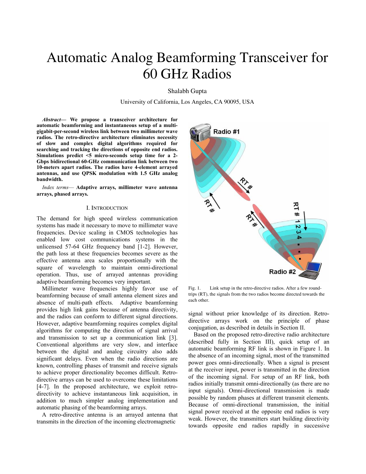
A retro-directive antenna is an arrayed antenna that transmits in the direction of the incoming electromagnetic Link setup in the retro-directive radios. After a few roundtrips (RT), the signals from the two radios become directed towards the each other.
signal without prior knowledge of its direction. Retrodirective arrays work on the principle of phase conjugation, as described in details in Section II.
Based on the proposed retro-directive radio architecture (described fully in Section III), quick setup of an automatic beamforming RF link is shown in Figure 1. In the absence of an incoming signal, most of the transmitted power goes omni-directionally. When a signal is present at the receiver input, power is transmitted in the direction of the incoming signal. For setup of an RF link, both radios initially transmit omni-directionally (as there are no input signals). Omni-directional transmission is made possible by random phases at different transmit elements. Because of omni-directional transmission, the initial signal power received at the opposite end radios is very weak. However, the transmitters start building directivity towards opposite end radios rapidly in successive transmissions, as they start receiving more and more power after every signal round trip (RT). This positive feedback leads to a quick, automatically tracking RF link between the two radios.
This link setup process is analogous to target acquisition in the retro-directive noise correlation radar [8][9]. However, the threshold power requirements for setting up the link are much smaller as compared to the retro-directive radar since there are active transmitters on both ends.
The retro-directive arrays, also known as self-phasing antennas, rely on the principle of phase-conjugation (or phase inversion) for their operation. Traditionally, they have been used as passive transponders, in which any incoming signal is reflected back to the source. When the incoming wave is phase conjugated, both the incoming and the transmitted waves have parallel wave fronts, but travel in opposite directions. Phase conjugation can be achieved by Van Atta array arrangement, or by using heterodyne mixing, as discussed in the following subsections.
In Van Atta configuration [4], shown in Fig. 2(a), the signal received at one element is transmitted by another one which is at a “conjugate” position to it, after addition of a constant phase delay due to interconnects and intermediate circuitry. In the figure, for example, signal received at the first element is retransmitted by the fourth element, that received at the second element is transmitted by the third element, and so on. Starting from the source and returning back to the source, the signal undergoes equal phase delays for different paths, as L1 + L4 = L2 + L3, assuming adjacent elements are equidistant to each other. Hence, there is constructive interference of signals transmitted by all elements at the source resulting in directivity towards it. The signal can be transmitted passively or there can be active components in the signal path to modulate and/or amplify the signal before transmission.
Use of heterodyne mixing technique to achieve phase conjugation was first proposed in [5]. As in Figure 2(b), when the wave-front from the source is incident at nonzero angle, each array element receives the RF with a different phase due to path length difference. Element i is at distance L i away from the source and the signal obtai
This content is AI-processed based on open access ArXiv data.