The MultiNoC system implements a programmable on-chip multiprocessing platform built on top of an efficient, low area overhead intra-chip interconnection scheme. The employed interconnection structure is a Network on Chip, or NoC. NoCs are emerging as a viable alternative to increasing demands on interconnection architectures, due to the following characteristics: (i) energy efficiency and reliability; (ii) scalability of bandwidth, when compared to traditional bus architectures; (iii) reusability; (iv) distributed routing decisions. An external host computer feeds MultiNoC with application instructions and data. After this initialization procedure, MultiNoC executes some algorithm. After finishing execution of the algorithm, output data can be read back by the host. Sequential or parallel algorithms conveniently adapted to the MultiNoC structure can be executed. The main motivation to propose this design is to enable the investigation of current trends to increase the number of embedded processors in SoCs, leading to the concept of "sea of processors" systems.
This work presents the implementation of multiprocessing systems, connected through a NoC. According to ITRS estimation, in 2012, SoCs will have hundreds of IP cores, operating at clock frequencies near 10 GHz. In this context, a Network-on-Chip (NoC) [1] appears as a possible solution for future on-chip interconnections. A NoC is an on-chip network composed by IP cores connected to routers, which are interconnected by communication channels. Another motivation to present this design is the current trend to increase the number of embedded processors in SoCs, leading to the concept of "sea of processors" systems [6].
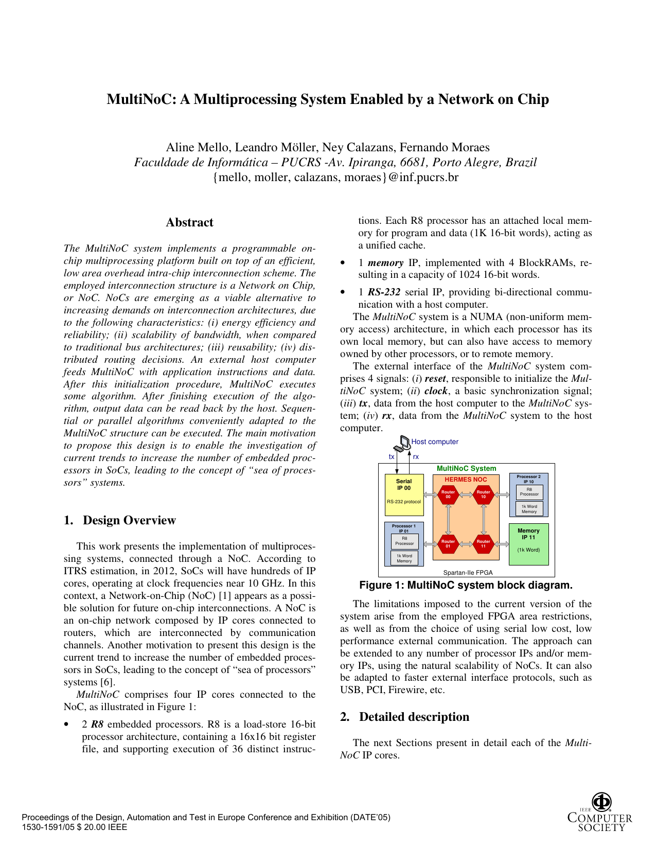
MultiNoC comprises four IP cores connected to the NoC, as illustrated in Figure 1:
• 2 R8 embedded processors. R8 is a load-store 16-bit processor architecture, containing a 16x16 bit register file, and supporting execution of 36 distinct instruc-tions. Each R8 processor has an attached local memory for program and data (1K 16-bit words), acting as a unified cache.
• 1 memory IP, implemented with 4 BlockRAMs, resulting in a capacity of 1024 16-bit words.
• 1 RS-232 serial IP, providing bi-directional communication with a host computer.
The MultiNoC system is a NUMA (non-uniform memory access) architecture, in which each processor has its own local memory, but can also have access to memory owned by other processors, or to remote memory.
The external interface of the MultiNoC system comprises 4 signals: (i) reset, responsible to initialize the Mul-tiNoC system; (ii) clock, a basic synchronization signal; (iii) tx, data from the host computer to the MultiNoC system; (iv) rx, data from the MultiNoC system to the host computer. The limitations imposed to the current version of the system arise from the employed FPGA area restrictions, as well as from the choice of using serial low cost, low performance external communication. The approach can be extended to any number of processor IPs and/or memory IPs, using the natural scalability of NoCs. It can also be adapted to faster external interface protocols, such as USB, PCI, Firewire, etc.
The next Sections present in detail each of the Multi-NoC IP cores.
The Hermes NoC employs packet switching, a communication mechanism in which packets are individually routed between cores, with no previously established communication path [5]. The wormhole packet switching mode is used to avoid the need for large buffer spaces [9]. The routing algorithm defines the path taken by a packet between the source and the destination. The deterministic XY routing algorithm is employed.
The Hermes NoC follows a mesh topology, justified to facilitate routing, IP cores placement and chip layout generation. The routers in MultiNoC use an 8-bit flit size, and the number of flits in a packet is fixed at 2 (flit size in bits) . The first and the second flits of a packet are header information, being respectively the address of the target router, named header flit, and the number of flits in the packet payload. An asynchronous handshake protocol is used between neighbor routers. The physical interface between routers is composed by the following signals:
• tx: control signal indicating data availability;
• data_out: data to be sent; The control logic implements the routing and arbitration algorithms. When a router receives a header flit, arbitration is performed, and if the incoming packet request is granted, an XY routing algorithm is executed to connect the input port data to the correct output port. If the chosen port is busy, the header flit, as well as all subsequent flits of this packet, will be blocked in the input buffers. The routing request for this packet will remain active until a connection is established in some future execution of the procedure in this router. When the XY routing algorithm finds a free output port to use, the connection between the input port and the output port is established. After routing all flits of the packet, connection is closed. At the operating frequency of 50MHz, with a word size (flit) of 8 bits the theoretical peak throughput of each Hermes router is 1Gbits/s.
A router can establish up to five connections simultaneously. Arbitration logic is used to grant access to an output port when one or more input ports require a connection at the same time. A round-robin arbitration scheme is used to avoid starvation.
When a flit is blocked in a given router, the performance of the network is affected, since several flits belonging to the same packet may be blocked in several intermediate routers. To lessen the performance loss, a 2-flit buffer is added to each input router port, reducing the number of routers affected by the blocked flits. Larger buffers can provide enhanced NoC performance. Multi-NoC employs small buffers to cope with FPGA area restrictions. The inserted buffers work as circular FIFOs.
The minimal latency in clock cycles to transfer a packet from source to destination is given by: ( )
where: n is the number of rout
This content is AI-processed based on open access ArXiv data.