A Class of Axis-Angle Attitude Control Laws for Rotational Systems
We introduce a new class of attitude control laws for rotational systems; the proposed framework generalizes the use of the Euler \mbox{axis--angle} representation beyond quaternion-based formulations. Using basic Lyapunov stability theory and the no…
Authors: Francisco M. F. R. Gonçalves, Ryan M. Bena, Néstor O. Pérez-Arancibia
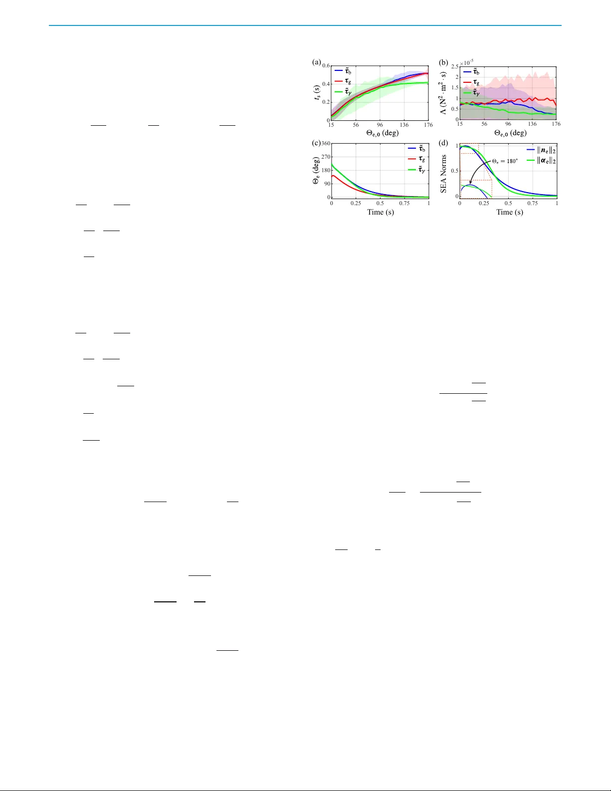
IEEE CONTROL SYSTEMS LETTERS , V OL. 10, 2026 157 A Class of Axis–Angle Attitude Control La ws f or Rotational Systems F rancisco M. F . R. Gonc ¸ alv es, Gr aduate Student Member , IEEE , Ryan M. Bena, Member , IEEE , and N ´ estor O . P ´ erez-Arancibia, Member , IEEE Abstract — We introduce a new class of attitude con- trol laws for rotational systems; the proposed framew ork generalizes the use of the Euler axis–angle represen- tation bey ond quaternion-based formulations. Using ba- sic Ly apunov stability theor y and the notion of e xtended class K function, we de veloped a method for determining and enfor cing the global asymptotic stability of the sin- gle fixed point of the resulting closed-loop (CL) scheme . In contrast with traditional quaternion-based methods, the introduced generalized axis–angle appr oach enables greater flexibility in the design of the contr ol law , which is of great utility when employed in combination with a switc hing scheme whose transition state depends on the angular velocity of the controlled rotational system. Through simulation and real-time experimental results, we demonstrate the effectiveness of the developed form ula- tion. Accor ding to the recorded data, in the execution of high-speed tumble-recovery maneuvers, the new method consistently achieves shorter stabilization times and re- quires lower control effort relative to those corresponding to the quaternion-based and geometric-control methods used as benchmarks. Index T erms — Axis–angle, attitude control, r obotics. I . I N T R O D U C T I O N N UMER OUS different types of attitude controllers ha ve been proposed f or stabilizing and commanding the tra- jectory of rotational sys tems that can be modeled as r igid bodies [1]–[16]. These controllers can be classified into three main types: (i) q uaternion-based, (ii) Euler -angles–based, and (iii) rotation-matr ix–based (geometric). The limitations of attitude controllers based on Euler angles ha v e been ex- tensiv el y studied and discussed in the technical literature— f or e xample, see [17] and ref erences therein. Due to these limitations, quaternion-based and geometric methods hav e been the preferred choices for representing and implementing robust high-per f ormance attitude controllers. Although these tw o f ormulations implicitly contain the kno wledg e about the Euler axis and associated rotation angle as defined in [18], this inf ormation is generall y not directly used in controller design. This w ork was suppor ted in par t b y the W ashington State University (WSU) Foundation and the Palouse Club through a Cougar Cage A ward to N. O. P ´ erez-Arancibia and in part by the WSU V oiland College of Engineering and Architecture through a star t-up pac kage to N. O. P ´ erez- Arancibia. F . M. F . R. Gonc ¸ alves and R. M. Bena contributed equally to this work. F . M. F . R. Gonc ¸ alves and N. O. P ´ erez-Arancibia are with the School of Mechanical and Materials Engineering, W ashington State Univer- sity (WSU), Pullman, WA 99164-2920, USA. R. M. Bena is with the Depar tment of Mechanical and Civil Engineering, California Insti- tute of T echnology , P asadena, CA 91125-2100, USA. Correspond- ing authors’ email: francisco.goncalves@wsu.edu (F . M. F . R. G.); n.perezarancibia@wsu.edu (N. O . P .-A.). For e xample, quaternion-based time-inv ariant attitude con- trol law s usually include a proportional ter m that is f ormed by scaling the attitude-er ror Euler axis with sin Θ e 2 , where Θ e is the corresponding instantaneous rotation er ror . How e v er, there is no reason f or this type of formulation other than ensuring continuity in the entire rotational space and simplifying the analy sis of the resulting closed-loop (CL) system. Counterintuitivel y , how ev er , in mos t practical applications, this continuous f ormulation is modified to obtain a switching or h ybrid scheme in order to a v oid unwinding beha vior [4]–[8]. Another characteristic of continuous quater nion-based control la w s is that, f or rotational errors larger than 𝜋 rad, the propor tional control effor t decreases as the rotational er ror about the attitude-error Euler axis increases. Also, it can be shown that geometric-based attitude control la w s implicitl y appl y torques in the direction of the shorter rotational trajectory required to eliminate the attitude error. As discussed in [1] and [2], this direction choice is not necessarily the best f or e v ery kinematic situation, depending on the specific performance objectiv es of the problem of interest. In this letter , we introduce a class of attitude control law s applicable to a wide gamut of r igid rotational systems mo ving in the t hr ee-dimensional (3D) space, including uncr ew ed aerial v ehicles (U A Vs), satellites, and microrobotic swimmers. The proposed method generalizes the use of the Euler axis–angle representation in the f ormulation of the f eedbac k law that stabilizes and drives the rotational motion of the controlled sys tem. It is w ell kno wn that global asymptotic stability on the special or thogonal group in three dimensions, S O ( 3 ) , cannot be achie ved with the use of continuous time-in v ariant f eedbac k controllers. A common technique used to o v ercome this topological obstruction is to design discontinuous control la w s [8]; another option is to define the CL dynamics of the controlled sys tem on a cov ering that generates a unique coordinate representation of S O ( 3 ) , rather than on S O ( 3 ) itself. Follo wing this latter approach, by combining L yapuno v stability theory and the notion of e xtended class K function, w e dev eloped a method that ensures the e xistence of a unique CL fixed attitude-error quat ernion (AEQ) and the global asymptotic stability of the corresponding eq uilibrium point, which depends on positive-definiteness conditions that the controller gains mus t satisfy . A main contribution of the w ork presented in this letter is the design fle xibility enabled b y a generalized f ormula- tion of the propor tional ter m in the proposed control la w; specifically , it allow s the user to select a suitable propor tional control function based on the platf orm and/or application, with stability guarantees. Fur thermore, in contrast to exis t- ing quaternion-based control methods, the new generalized axis–angle attitude control approach ensures a g reater propor- © 2026 IEEE. This w ork has been published in IEEE Contr ol Sy st ems Le tters . Personal use of this mater ial is permitted. Permission from IEEE must be obtained for all other uses. 158 IEEE CONTROL SYSTEMS LETTERS , V OL. 10, 2026 tional action the farther the sy stem’ s state is from the stable CL fixed AEQ. This characteristic is especially useful when a scheme of the proposed type is emplo y ed in combination with intelligent switching methods capable of taking into account the angular velocity when selecting the direction in which the proportional component of the input torque is applied dur ing operation, as for e x ample done in the case presented in [1]. W e tested the functionality and per f ormance of the introduced approach through simulations and outdoor flight tests. The obtained simulation and e xper imental data sho w that, compared to two other high-per f ormance benchmark controllers—one quaternion-based and another g eometric—a scheme of the ne w type is unequiv ocally superior . Specificall y , measurements obtained through dozens of high-speed tumble-reco v er y ma- neuv ers sho w that the presented approac h consistentl y achiev es shorter stabilization times and requires less control effort, from a statis tical standpoint. N otation— 1) Low ercase symbols represent scalars, e.g., 𝑝 ; bold low - ercase symbols denote vectors, e.g., 𝒑 ; bold uppercase symbols denote matr ices, e.g., 𝑷 ; and, bold crossed lo w ercase symbols denote quaternions, e.g., ¯ 𝒑 . 2) The set of unit 3D vectors is denoted b y S 2 . 3) The sets of reals and positiv e reals are denoted by R and R > 0 , respectiv el y . The set of integ ers is denoted b y Z . 4) The symbols × and ⊗ denote the cross-product of tw o v ectors and multiplication betw een tw o quaternions, respectiv el y . 5) Throughout the rest of the paper , w e use the notion of e xtended class K function as defined in [19]. I I . B A C K G R O U N D W e first descr ibe the dynamics of a r igid body rotating in the 3D space. As sho wn in Fig. 1 , B = { 𝒃 1 , 𝒃 2 , 𝒃 3 } denotes the body -fix ed frame of ref erence, with its or igin coinciding with the body’s center of mass (CoM), used f or kinematic de- scription and dynamic analy sis. Consistent with this definition, I = { 𝒊 1 , 𝒊 2 , 𝒊 3 } denotes the chosen iner tial frame of reference fix ed to the planet. As discussed in [4] and [5], using quater nions and Euler’ s second law , the open-loop rotational dynamics of the sys tem can be described as ¤ ¯ 𝒒 = 1 2 ¯ 𝒒 ⊗ 0 𝝎 , (1a) ¤ 𝝎 = 𝑱 − 1 ( 𝝉 − 𝝎 × 𝑱 𝝎 ) , (1b) in whic h ¯ 𝒒 is a unit quaternion that represents the orientation of B relativ e to I ; 𝝎 is the angular velocity of B with respect to I , written in B coordinates; 𝑱 is the inertia matrix of the body , written in B coordinates; and, 𝝉 is the torque applied to the sys tem wr itten in B coordinates and, in closed loop, generated b y a control la w . As specified by Euler’ s rotation theorem, an y sequence of rotations of a rigid body in the 3D space is equivalent to a single rotation of amount Θ about an axis 𝒖 that passes through the body’ s CoM. This inf ormation can be stored in the f or m of a unit quaternion as ¯ 𝒒 = 𝑚 𝒏 𝑇 𝑇 , where 𝑚 = cos Θ 2 and 𝒏 = 𝒖 sin Θ 2 . In the case specified by ( 1a ), Θ is the amount that the modeled body must be rotated about 𝒖 to reach the attitude of B starting from that of I . Accordingl y , the instantaneous Fig. 1. Flight control tests and frames of reference. This picture shows the UA V , a Crazyflie 2.1, used in the control experiments, and the iner tial and body-fixed frames of reference, I = { 𝒊 1 , 𝒊 2 , 𝒊 3 } and B = { 𝒃 1 , 𝒃 2 , 𝒃 3 } . Here, B , whose origin coincides with the robot’ s CoM, is shown shifted f or clarity . AEQ is giv en by ¯ 𝒒 e = ¯ 𝒒 − 1 ⊗ ¯ 𝒒 d = 𝑚 e 𝒏 𝑇 e 𝑇 , with 𝑚 e = cos Θ e 2 and 𝒏 e = 𝒖 e sin Θ e 2 , where Θ e is the amount that B must be rotated about the attitude-er ror Euler axis, 𝒖 e , to reach the orientation of the desired body-fix ed frame, B d ; and, ¯ 𝒒 d is a unit quaternion that represents the attitude of B d relativ e to I . In practice, ¯ 𝒒 d is either defined by the user , as described in Section IV , or generated b y a position control scheme, as e xplained in [4]. An y real-time control algorithm based on the f ormulation specified b y ( 1b ) requires the desired angular v elocity of the controlled rotational sy stem in B coordinates, 𝝎 d . T o compute this v ariable, we firs t obtain the cor responding desired angular -v elocity quater nion, written in B d coordinates, according to 0 ˆ 𝝎 d = 2 ¯ 𝒒 − 1 d ⊗ ¤ ¯ 𝒒 d . (2) Then, w e compute 𝝎 d = 𝑺 𝑇 𝑺 d ˆ 𝝎 d , where 𝑺 d transf orms v ectors from B d to I coordinates, and 𝑺 𝑇 transf orms v ectors from I to B coordinates. Thus, using these kinematic variables, w e can define a control la w that computes the torque in put as 𝝉 b = 𝑱 𝑘 ¯ 𝒒 𝒏 e + 𝑘 𝝎 𝝎 e + ¤ 𝝎 d + 𝝎 × 𝑱 𝝎 , (3) where 𝑘 ¯ 𝒒 and 𝑘 𝝎 are scalar positiv e real controller gains; 𝝎 e = 𝝎 d − 𝝎 is the angular -velocity tracking er ror; 𝑱 ¤ 𝝎 d is a f eedf or ward ter m that appro ximately cancels the left-hand side of ( 1b ) and is included with the objectiv e of providing fas ter tracking per f ormance; and, 𝝎 × 𝑱 𝝎 is a f eedback -linearization term that cancels the nonlinear ity present in ( 1b ). As discussed in [4], the CL rotational dynamics obtained b y substituting the right-hand side of ( 3 ) into ( 1b ) e xhibit two equilibria cor responding to the same kinematic condition but with different stability properties—one asymptotically stable and the other unstable. It is straightf orward to see that, at both fixed points, 𝒏 e = 0 . Therefore, if the state of the CL sys tem were to be e xactl y at the unstable equilibrium, the control torque specified b y ( 3 ) w ould not compel the controlled rotational sys tem to e x ecute a 2 𝜋 -rad rotation and con v er ge to the stable equilibrium, thus pre v enting global asymptotic stability on S O ( 3 ) . Ho w e v er , in an y real-wor ld application, any deviation from the unstable fixed point w ould make 𝒏 e ≠ 0 and, theref ore, f or all practical pur poses, we can confidentl y assume that the torque generated according to ( 3 ) forces the CL sys tem’ s state to con v erg e to the stable equilibrium. A dditionally , note that since 𝒏 e is scaled by the factor sin Θ e 2 , the first ter m in ( 3 ) does not pro vide the maximum allow able control effor t when © 2026 IEEE. This w ork has been published in IEEE Contr ol Sy st ems Le tters . Personal use of this mater ial is permitted. Permission from IEEE must be obtained for all other uses. GONC ¸ AL VES et al. : A CLASS OF AXIS–ANGLE A TTITUDE CONTROL LA WS FOR ROT A TIONAL SYSTEMS 159 the controlled rotational sys tem is at the f arthest or ientation from the stable CL equilibrium AEQ. In fact, this ter m reaches its minimum value at the unstable CL fixed AEQ, where Θ e = 2 𝜋 rad; its maximum at Θ e = 𝜋 rad; and, its minimum again at the stable CL equilibrium AEQ, where Θ e = 0 rad. These obser vations contradict the e xpected beha vior of the proportional action of a feedbac k controller . W e address these representational, stability , and performance issues in the ne xt section by proposing a ne w g eneralized axis–angle attitude law f or controlling rotational sy stems in the 3D space. I I I . G E N E R A L I Z E D A X I S – A N G L E A T T I T U D E C O N T R O L A. A New Class of Control Laws Let 𝛾 : R ↦→ R be an e xtended class K function. Then, for a sys tem whose dynamics ev olv e on S O ( 3 ) , the rotational er rors to be minimized can be represented as 𝜶 e = 𝛾 ( Θ e ) 𝒖 e and 𝝎 e , (4) where 𝜶 e is a scaled Euler axis (SEA) aligned with 𝒖 e , whose magnitude—measured by an y vector norm—scales with the value of Θ e . Without loss of co v erag e of S O ( 3 ) , Θ e can be restricted to any half-open interval spanning 2 𝜋 that includes 0; in this letter , we consider Θ e ∈ [ 0 , 2 𝜋 ) . Consistent with this selection, f or an y Θ e ≠ 0, an axis–angle pair , { 𝒖 e , Θ e } , uniquel y defines one of the two possible rotations—with op- posite directions—that w ould cancel the instantaneous attitude error of the controlled rotational system. When Θ e = 0, the corresponding rotation axis is not uniquel y defined and can take an y value in S 2 ; how ev er , 𝜶 e is still well defined. T o initialize simulations and e xperiments, we select the direction of rotation at initial time 𝑡 0 that minimizes, assuming Θ e ∈ [ 0 , 2 𝜋 ) , a two-v alued cost function, as described in [1]. Thus, using the errors specified b y ( 4 ), we define the proposed generic control la w as 𝝉 𝛾 = 𝑱 ( 𝑘 𝜶 𝜶 e + 𝑘 𝛿 ¤ 𝜶 e + 𝑘 𝝎 𝝎 e + ¤ 𝝎 d ) + 𝝎 × 𝑱 𝝎 , (5) in whic h 𝑘 𝜶 , 𝑘 𝛿 , and 𝑘 𝝎 ∈ R > 0 . Then, from simple subs titution of ( 4 ) into ( 5 ), w e obtain that 𝝉 𝛾 = 𝑱 [ 𝑘 𝜶 𝛾 ( Θ e ) 𝒖 e + 𝑘 𝛿 𝛾 ( Θ e ) ¤ 𝒖 e + 𝑘 𝛿 ¤ 𝛾 ( Θ e ) 𝒖 e + 𝑘 𝝎 𝝎 e + ¤ 𝝎 d ] + 𝝎 × 𝑱 𝝎 . (6) B. Closed-Loop Dynamics and Equilibr ium P oints It is straightf or ward to see that f or the control input defined b y ( 6 ), the CL rotational-error dynamics can be wr itten as ¤ ¯ 𝒒 e = 1 2 0 𝝎 e ⊗ ¯ 𝒒 e , (7a) ¤ 𝝎 e = − 𝑘 𝜶 𝛾 ( Θ e ) 𝒖 e − 𝑘 𝛿 𝛾 ( Θ e ) ¤ 𝒖 e + 𝑑 𝛾 𝑑 Θ e ( 𝒖 𝑇 e 𝝎 e ) 𝒖 e − 𝑘 𝝎 𝝎 e , (7b) in whose derivation w e used that ¤ Θ e = 𝒖 𝑇 e 𝝎 e . Ne xt, to find the equilibrium point(s) of the sys tem giv en b y ( 7a )–( 7b ), w e sol v e the set of algebraic eq uations specified b y − 1 2 𝒏 𝑇 e 𝝎 e = 0 , (8a) − 1 2 ( 𝒏 e × 𝝎 e − 𝑚 e 𝝎 e ) = 0 3 × 1 , (8b) − 𝑘 𝜶 𝛾 ( Θ e ) 𝒖 e − 𝑘 𝛿 𝛾 ( Θ e ) ¤ 𝒖 e − 𝑘 𝝎 𝝎 e = 0 3 × 1 . (8c) For ( 8b ) to be satisfied, both ter ms inside the parenthesis must be zero because they are or thogonal. For both these terms to be zero, one of the f ollo wing statements must hold: (i) 𝒏 e ∥ 𝝎 e and 𝑚 e = 0; (ii) 𝝎 e = 0 ; (iii) 𝒏 e = 𝝎 e = 0 . Also, f or ( 8a ) to be satisfied, either (ii) or (iii) is true, 𝒏 e = 0 , or 𝒏 e ⊥ 𝝎 e . Since 𝒏 e and 𝝎 e cannot simultaneousl y be orthogonal and parallel, the only viable option is either (ii) or (iii). The fulfillment of either (ii) or (iii) requires that the solution to ( 8a )–( 8c ) satisfies 𝝎 ★ e = 0 . Since 𝒖 e is a v ector ev ol ving on S 2 , it follo ws that 𝒖 e ⊥ ¤ 𝒖 e and, therefore, for ( 8c ) to be satisfied, 𝛾 ( Θ e ) = 0. Last, recalling that 𝛾 ( Θ e ) is an extended class K function and, theref ore, 𝛾 ( 0 ) = 0, we conclude that Θ ★ e = 0. For the la w specified b y ( 6 ), w e selected 𝛾 ( Θ e ) to be an e xtended class K function in order to enf orce the exis tence of a unique zero f or 𝛾 ( Θ e ) and a unique equilibr ium point f or the CL dynamics giv en b y ( 7a )–( 7b ), o v er the selected range of Θ e . In summary , the CL dynamics resulting from using the control input specified b y ( 6 ) exhibit a uniq ue equilibrium, given b y the quaternion–vector pair ¯ 𝒒 ★ e = [ 1 0 0 0 ] 𝑇 and 𝝎 ★ e = 0 , f or Θ e ∈ [ 0 , 2 𝜋 ) . This result does not contradict the topologi- cal obstruction discussed in [17]—according to which all continuous time-in v ariant CL vector fields on S O ( 3 ) must e xhibit multiple equilibr ia—as the CL dynamics are defined on an axis–angle cov er ing that g enerates a unique coordinate representation of each rotation in S O ( 3 ) , rather than on S O ( 3 ) itself. Fur ther more, for Θ e ∈ ( −∞ , ∞ ) , the term 𝛾 ( Θ e ) 𝒖 e is discontinuous at Θ e = 2 𝜋 𝑘 rad, f or all nonzero 𝑘 ∈ Z . As a result, the CL dynamics specified b y ( 7a )–( 7b ) are also discontinuous, which f orces the exis tence of a unique fix ed point, similarl y to the cases presented in [8]. Ho w ev er , discontinuities produce numerous e xperimental and theoretical problems; f or ex ample, to analyze the differential equations of the CL system specified b y ( 7a )–( 7b ) when Θ e ∈ ( −∞ , ∞ ) , w e mus t use Carath ´ eodory’s notion of solution, as stated in [20, Definition 2.1]. F or these reasons, Θ e ∈ [ 0 , 2 𝜋 ) is a super ior choice f or the problem considered in this letter . C . Stability Analysis Theorem 1. Let the attitude and angular -v elocity ref er - ences, ¯ 𝒒 d and 𝝎 d , be smooth and bounded functions of time. Also, let the real controller gains satisfy 𝑘 𝛿 > 0, 𝑘 𝝎 > 0, and 𝑘 𝜶 > 𝑘 𝛿 𝑘 𝝎 4 . Then, the fix ed point { Θ ★ e , 𝝎 ★ e } of the CL state-space rotational dynamics specified by ( 7a ) and ( 7b ) is globall y asymptotically stable on the domain D = { Θ e , 𝝎 e } Θ e ∈ [ 0 , 2 𝜋 ) , 𝝎 e ∈ R 3 , for any initial state { Θ e ( 𝑡 0 ) , 𝝎 e ( 𝑡 0 ) } ∈ D and 𝒖 e ( 𝑡 0 ) ∈ S 2 . Proof. Let a candidate L y apuno v function be 𝑉 = 𝛾 ( Θ e ) 𝒖 𝑇 e 𝝎 𝑇 e 𝑘 2 𝛿 2 𝑘 𝜶 𝑘 𝛿 2 𝑘 𝜶 𝑘 𝛿 2 𝑘 𝜶 1 2 𝑘 𝜶 𝛾 ( Θ e ) 𝒖 e 𝝎 e + Θ e 0 𝛾 ( 𝜙 ) 𝑑 𝜙, (9) f or Θ e ∈ [ 0 , 2 𝜋 ) . It is s traightf or ward to sho w that the eigen v al- ues of the matrix in the quadratic ter m of ( 9 ) are 𝜆 1 = 0 and 𝜆 2 = 𝑘 2 𝛿 + 1 2 𝑘 𝜶 . (10) © 2026 IEEE. This w ork has been published in IEEE Contr ol Sy st ems Le tters . Personal use of this mater ial is permitted. Permission from IEEE must be obtained for all other uses. 160 IEEE CONTROL SYSTEMS LETTERS , V OL. 10, 2026 Theref ore, the quadratic ter m in ( 9 ) is positiv e semidefinite and 𝑉 is positive definite because the integ ral term is positive definite with respect to Θ e ∈ [ 0 , 2 𝜋 ) , f or an y e xtended class K function 𝛾 . T o continue, w e e xpand 𝑉 as 𝑉 = 𝑘 2 𝛿 2 𝑘 𝜶 𝛾 2 ( Θ e ) + 𝑘 𝛿 𝑘 𝜶 𝛾 ( Θ e ) 𝒖 𝑇 e 𝝎 e + 1 2 𝑘 𝜶 𝝎 𝑇 e 𝝎 e + Θ e 0 𝛾 ( 𝜙 ) 𝑑 𝜙, (11) and compute its time derivativ e, whic h yields ¤ 𝑉 = 𝑘 2 𝛿 𝑘 𝜶 𝛾 ( Θ e ) 𝑑 𝛾 𝑑 Θ e ¤ Θ e + 𝑘 𝛿 𝑘 𝜶 𝑑 𝛾 𝑑 Θ e ¤ Θ e 𝒖 𝑇 e 𝝎 e + 𝛾 ( Θ e ) ¤ 𝒖 𝑇 e 𝝎 e + 𝛾 ( Θ e ) 𝒖 𝑇 e ¤ 𝝎 e + 1 𝑘 𝜶 𝝎 𝑇 e ¤ 𝝎 e + 𝛾 ( Θ e ) ¤ Θ e . (12) This e xpression can be simplified b y recalling that ¤ Θ e = 𝒖 𝑇 e 𝝎 e , noticing that ¤ 𝒖 𝑇 e 𝒖 e = 0 because 𝒖 e ∈ S 2 , and substituting ( 7b ) into ( 12 ). Namel y , ¤ 𝑉 = 𝑘 2 𝛿 𝑘 𝜶 𝛾 ( Θ e ) 𝑑 𝛾 𝑑 Θ e 𝒖 𝑇 e 𝝎 e + 𝑘 𝛿 𝑘 𝜶 𝑑 𝛾 𝑑 Θ e 𝒖 𝑇 e 𝝎 e 𝒖 𝑇 e 𝝎 e + 𝛾 ( Θ e ) ¤ 𝒖 𝑇 e 𝝎 e − 𝑘 𝜶 𝛾 2 ( Θ e ) − 𝑘 𝛿 𝛾 ( Θ e ) 𝑑 𝛾 𝑑 Θ e ( 𝒖 𝑇 e 𝝎 e ) − 𝑘 𝝎 𝛾 ( Θ e ) 𝒖 𝑇 e 𝝎 e + 1 𝑘 𝜶 𝝎 𝑇 e − 𝑘 𝜶 𝛾 ( Θ e ) 𝒖 e − 𝑘 𝛿 𝛾 ( Θ e ) ¤ 𝒖 e + 𝑑 𝛾 𝑑 Θ e ( 𝒖 𝑇 e 𝝎 e ) 𝒖 e − 𝑘 𝝎 𝝎 e + 𝛾 ( Θ e ) 𝒖 𝑇 e 𝝎 e . (13) Thus, after canceling out the ter ms with equal magnitudes and opposite signs, w e obtain ¤ 𝑉 = − 𝑘 𝛿 𝛾 2 ( Θ e ) − 𝑘 𝛿 𝑘 𝝎 𝑘 𝜶 𝛾 ( Θ e ) 𝒖 𝑇 e 𝝎 e − 𝑘 𝝎 𝑘 𝜶 𝝎 𝑇 e 𝝎 e = − 𝛾 ( Θ e ) 𝒖 𝑇 e 𝝎 𝑇 e 𝑾 𝛾 ( Θ e ) 𝒖 e 𝝎 e , (14) where 𝑾 = 𝑘 𝛿 𝑘 𝛿 𝑘 𝝎 2 𝑘 𝜶 𝑘 𝛿 𝑘 𝝎 2 𝑘 𝜶 𝑘 𝝎 𝑘 𝜶 , (15) which can be made positiv e definite by selecting { 𝑘 𝛿 , 𝑘 𝝎 } > 0 and 𝑘 𝜶 > 𝑘 𝛿 𝑘 𝝎 4 , (16) thus also enf orcing that ¤ 𝑉 ( Θ e , 𝝎 e ) < 0 f or all { Θ e , 𝝎 e } ≠ { Θ ★ e , 𝝎 ★ e } , and ¤ 𝑉 Θ ★ e , 𝝎 ★ e = 0. In summary , 𝑉 is positive definite on D and coercive in 𝝎 e ; theref ore, proper on D . Moreo v er , since ¤ 𝑉 is negativ e definite on D , we conclude that the unique equilibrium of the CL dynamics giv en by ( 7a )–( 7b ) is globally asymptotically stable on D , which, together with S 2 , pro vides a complete co v er ing of S O ( 3 ) . □ T ime (s) (a) (b) (c) T ime (s) (d) SEA Norms Fig. 2. Numerical results obtained with Crazyflie 2.1 parameters, using quaternion-based, geometric, and axis–angle control laws. (a) Mean and ESD of the stabilization time as functions of the initial rotation error . (b) Mean and ESD of the control eff or t as functions of the initial rotation error . (c) Time e volution of the rotation error associated with the attitude-error Euler axis. (d) Time ev olution of the SEA magnitudes corresponding to the simulated quater nion-based and proposed axis–angle laws . D . Discussion There e xist infinitely many valid choices of 𝛾 functions; some superior to the rest. F or e xample, a sigmoid function is an e xtended class K function that provides tunable saturation while maintaining linearity near the equilibr ium. Namel y , 𝛾 ( Θ e ) = Θ max 1 − 𝑒 − 𝜉 Θ e Θ max 1 + 𝑒 − 𝜉 Θ e Θ max , (17) where Θ max and 𝜉 are design parameters. In this conte xt, Θ max is the angle at which the maximum magnitude of the actuation torque occurs and 𝜉 deter mines the rate at which the magnitude of 𝛾 ( Θ e ) chang es with respect to Θ e . T aking the der ivativ e of ( 17 ) with respect to Θ e yields 𝑑 𝛾 𝑑 Θ e = 2 𝜉 𝑒 − 𝜉 Θ e Θ max 1 + 𝑒 − 𝜉 Θ e Θ max 2 , (18) which provides insights and can be used to guide the process of controller synthesis. In particular , the slope at the origin has the f orm 𝑑 𝛾 𝑑 Θ e ( 0 ) = 𝜉 2 , where 𝜉 can be tuned consider ing actuator limitations and control objectiv es. I V . S I M U L A T I O N A N D E X P E R I M E N T A L R E S U L T S A. Numerical Simulations T o systematicall y assess the functionality and performance of the proposed generalized control la w , w e compared a controller synthesized using this ne w approach with two benchmark sc hemes through numer ical simulations. The first scheme used f or compar ison uses the quaternion-based atti- tude control la w specified by ( 3 ), 𝝉 b ; the second is the high- performance geometric approach presented in [12], whose corresponding attitude control law here we denote by 𝝉 g . W e implemented and ex ecuted the numer ical simulations in Simulink 25.2 (MA TLAB R2025b), using the Dor mand–Pr ince algorithm with a fixed time step of 10 − 4 s. The simulations w ere set up using the open-loop dynamical model speci- © 2026 IEEE. This w ork has been published in IEEE Contr ol Sy st ems Le tters . Personal use of this mater ial is permitted. Permission from IEEE must be obtained for all other uses. GONC ¸ AL VES et al. : A CLASS OF AXIS–ANGLE A TTITUDE CONTROL LA WS FOR ROT A TIONAL SYSTEMS 161 fied b y ( 1a )–( 1b ) with the parameters of the Crazyflie 2.1 platf orm—sho wn in Fig. 1 —and controllers with empir - ically selected gains that satisfy the stability condi- tions f or the three compared la w s. Specifically , w e used 𝑱 = diag { 16 . 6 , 16 . 7 , 29 . 3 } × 10 − 6 kg · m 2 , 𝑘 ¯ 𝒒 = 10 3 s − 2 , and 𝑘 𝝎 = 10 2 rad − 1 · s − 1 f or 𝝉 b specified b y ( 3 ). For 𝝉 𝛾 speci- fied by ( 5 ), w e used the same 𝑱 and 𝑘 𝝎 that f or 𝝉 b , and 𝑘 𝜶 = 10 3 rad − 1 · s − 2 , 𝑘 𝛿 = 10 rad − 1 · s − 1 , and the function 𝛾 ( Θ e ) defined by ( 17 ). For 𝛾 ( Θ e ) , we used Θ max = 1 rad and 𝜉 = 1 . 5, which were chosen consider ing the characteristics of the actuators dr iving the e xperimental platf orm. The controller gains f or 𝝉 g w ere specified to ensure a fair compar ison. For consistency with pre vious published results, w e implemented both 𝝉 𝛾 and 𝝉 b in combination with the model predictiv e selection (MPS) algorithm presented in [1], according to whic h the instantaneous direction of 𝒖 e , encoded by 𝜎 ∈ { − 1 , + 1 } , minimizes Γ ( 𝜎 , 𝑡 ) = 𝑡 + 𝑡 h 𝑡 𝝉 𝑇 ( 𝜎 , 𝜁 ) 𝑹 𝝉 ( 𝜎 , 𝜁 ) + 𝒏 𝑇 e ( 𝜁 ) 𝑸 𝒏 e ( 𝜁 ) 𝑑𝜁 , (19) in which 𝑡 h = 0 . 2 s; 𝑹 = 𝑰 , where 𝑰 is the identity matrix; and, 𝑸 = 10 − 6 × 𝑰 N 2 · m 2 . In the simulations, 𝝉 ∈ { ˜ 𝝉 b ( 𝜎 ) , ˜ 𝝉 𝛾 ( 𝜎 ) } , with ˜ 𝝉 b ( 𝜎 ) defined as in [1] and ˜ 𝝉 𝛾 ( 𝜎 ) = 𝑱 [ 𝑘 𝜶 𝜶 e ( 𝜎 ) + 𝑘 𝛿 ¤ 𝜶 e ( 𝜎 ) + 𝑘 𝝎 𝝎 e + ¤ 𝝎 d ] + 𝝎 × 𝑱 𝝎 , (20) in which 𝜶 e ( 𝜎 ) = 𝜎 𝛾 ( Φ e ) 𝒖 e and Φ e = ( 1 − 𝜎 ) 𝜋 + 𝜎 Θ e . Note that f or 𝜎 = + 1, Φ e = Θ e , and f or 𝜎 = − 1, Φ e = 2 𝜋 − Θ e . In total, we per f ormed 10 908 simulations of high-speed tumble-reco v ery maneuv ers, in which the control objective w as to stabilize the or ientation of the U A V from an initial state with arbitrary attitude and angular v elocity . Consistent with attitude regulation, f or each simulation, the desired state w as set to ¯ 𝒒 d = [ 1 0 0 0 ] 𝑇 and 𝝎 d = 0 rad · s − 1 . The directions of the initial Euler axes of rotation, 𝒖 0 = 𝒖 ( 𝑡 0 ) , were randomly selected from the unit sphere using a unif orm distribution, and the initial rotations about 𝒖 0 , Θ 0 = Θ ( 𝑡 0 ) , were taken from the set [ 1 : 180 ] ° in steps of 5 ° . For each Θ 0 , w e varied the initial angular v elocity , 𝝎 0 , from − 30 · 𝒖 0 to 30 · 𝒖 0 rad · s − 1 with the signed magnitude incremented in s teps of 0 . 6 rad · s − 1 . For eac h simulated Θ 0 value, w e computed the mean and experimental standar d deviation (ESD) of the set of stabilization times, { 𝑡 s } — with 𝑡 s defined as the time it tak es f or Θ e to reach a v alue low er than 15 ° —cor responding to the set of 101 different simulated signed magnitudes of 𝝎 0 . Fig. 2 (a) sho w s ho w the mean (solid line) and ESD (reduced-opacity band) of the stabilization time vary as functions of the initial rotation er ror , Θ e , 0 = Θ e ( 𝑡 0 ) , f or the three controllers. As seen, the means of the stabilization times obtained with the three controllers are similar f or small values of Θ e , 0 ; how ev er , f or larg er v alues of Θ e , 0 , the means obtained with ˜ 𝝉 𝛾 are notably smaller , e v en though 𝝉 g produces a better per f ormance in some cases—e videnced b y the ESD data. Fig. 2 (b) show s the mean and ESD of the set of control efforts, { Λ } —where Λ = 1 0 ∥ 𝝉 ( 𝑡 ) ∥ 2 2 𝑑 𝑡 , f or 𝝉 ∈ { ˜ 𝝉 b , 𝝉 g , ˜ 𝝉 𝛾 } — as functions of Θ e , 0 , f or the same simulations cor responding to Fig. 2 (a). Although the means of the control efforts obtained with the three controllers are similar f or small values of Θ e , 0 , the values of Λ cor responding to ˜ 𝝉 b and ˜ 𝝉 𝛾 decrease as Θ e , 0 increases. Notabl y , the controller designed using the proposed method consistentl y requires less control effor t while achie ving a lo w er mean stabilization time compared to the tw o Start and Stop Commands Flight Data Fig. 3. Experimental setup used during the flight tests. The attitude control flight experiments were run outdoors using a ground computer equipped with the Crazyradio 2.0 to communicate with the Crazyflie 2.1. benchmark controllers. Fig. 2 (c) sho w s the time e v olution of Θ e corresponding to the three simulated control law s, with an initial condition of Θ 0 = 136 ° and 𝝎 0 = 30 · 𝒖 0 rad · s − 1 . This initial state coincides with a kinematic condition in which the direction of the sys tem’ s initial angular v elocity is opposite to that of the shorter rotational path required to eliminate the attitude er ror . As seen, the controller based on ˜ 𝝉 𝛾 achie v es a stabilization time of 0 . 45 s whereas the benchmark controllers—with law s ˜ 𝝉 b and 𝝉 g —achie v e stabilization times of 0 . 58 and 0 . 49 s, respectiv el y . The initial rotation er ror , Θ e , 0 , f or the ˜ 𝝉 b and ˜ 𝝉 𝛾 cases is 224 ° , whic h means that these tw o law s applied the proportional component of the control torque in the direction of the longer rotational path required to eliminate the attitude er ror . Fig. 2 (d) sho w s the corresponding SEA norms, ∥ 𝒏 e ∥ 2 and ∥ 𝜶 e ∥ 2 . As seen, ∥ 𝒏 e ∥ 2 increases as the rotation er ror , Θ e , decreases from 224 ° do wn to 180 ° and starts decreasing after passing through that point (see inset), whic h highlights the c haracteristic beha vior of quaternion-based controllers. In contrast, ∥ 𝜶 e ∥ 2 increases and decreases with Θ e , as intended b y design. B. Real-Time Flight Exper iments T o fur ther assess and demons trate the suitability and per - f ormance of the proposed axis–angle control approach, w e performed real-time flight experiments using the same three controllers described in Section IV -A . As depicted in Fig. 3 , the flight tests were conducted outdoors, using a ground computer —eq uipped with the Crazyradio 2.0 2 . 4-GHz USB radio transceiv er —to send initialization and stop commands, and collect the flight and control data at a rate of 100 Hz. During each test, the U A V was commanded to e x ecute a high-speed tumble-reco very maneuv er after a thro w launch. A representative experiment consists of two stag es. Firs t, the tested U A V is thro wn into the air with an unkno wn high angular v elocity , while the controller and propellers remain inactiv e; then, the controller and propellers are activ ated. Throughout a maneuv er , the flier operates entirely autonomousl y , using only onboard sensing and computation, with the tested attitude controller running at 500 Hz. Fig. 4 (a) presents the time ev olution of Θ e f or three different e xperiments with similar initial conditions, using the three tested control law s. As seen, the stabilization times cor responding to ˜ 𝝉 b , 𝝉 g , and ˜ 𝝉 𝛾 are 0 . 57, 0 . 50, and 0 . 48 s, respectiv el y . Interestingl y , the corresponding v alues of Λ f or the 𝝉 g and ˜ 𝝉 𝛾 la w s are 1 . 76 × 10 − 4 and 4 . 56 × 10 − 5 N 2 · m 2 · s, which indicates that the proposed method achie v ed a lo w er s tabilization © 2026 IEEE. This w ork has been published in IEEE Contr ol Sy st ems Le tters . Personal use of this mater ial is permitted. Permission from IEEE must be obtained for all other uses. 162 IEEE CONTROL SYSTEMS LETTERS , V OL. 10, 2026 T ime (s) T ime (s) (a) SEA Norms (b) (c) (d) Control Law Control Law Fig. 4. Experimental flight results. (a) Rotation errors, as functions of time, corresponding to tests perf ormed using ˜ 𝝉 b , 𝝉 g , and ˜ 𝝉 𝜸 . (b) Time ev olutions of the SEA magnitudes, ∥ 𝒏 e ∥ 2 and ∥ 𝜶 e ∥ 2 , corresponding to the tests perf ormed using ˜ 𝝉 b and ˜ 𝝉 𝜸 , respectively , shown in (a). (c) Comparison of the means (circles) and SEM values (v er tical bars) of the stabilization times, corresponding to 30 independent tests per control la w , f or flights perf ormed using ˜ 𝝉 b , 𝝉 g , and ˜ 𝝉 𝜸 . (d) Comparison of the means and SEM v alues of the control eff or ts corresponding to the same 30 tests per control law of the data sho wn in (c). time using only about 25 % of the control effort measured f or the geometric-control case. Fig. 4 (b) presents the time ev olutions of the SEA nor ms ∥ 𝒏 e ∥ 2 and ∥ 𝜶 e ∥ 2 . Similarl y to the simulation cases discussed in Section IV -A , it can be observed that ∥ 𝒏 e ∥ 2 increases as Θ e decreases do wn to 180 ° from approximatel y 270 ° , and decreases after passing through this point. In contrast, o v er the entire range of operation, ∥ 𝜶 e ∥ 2 decreases and increases with Θ e , as intended b y design. Exper iments of this type can be vie w ed in the video a v ailable as a Supplemental Item. In Fig. 4 (c), each data point indicates the mean and standard error of the mean (SEM) of the s tabilization times cor respond- ing to 30 back -to-back e xperiments perf ormed using each of the three control law s compared in this letter . The means of the s ta- bilization times corresponding to ˜ 𝝉 b , 𝝉 g , and ˜ 𝝉 𝛾 are 0 . 74, 0 . 61, and 0 . 55 s, respectiv el y . In Fig. 4 (d), each data point indicates the mean and SEM of the control effor ts, Λ , corresponding to the same e xperiments of the data sho wn in F ig. 4 (c). The means of the Λ v alues corresponding to ˜ 𝝉 b , 𝝉 g , and ˜ 𝝉 𝛾 are 3 . 47 × 10 − 4 , 3 . 02 × 10 − 4 , and 2 . 15 × 10 − 4 N 2 · m 2 · s, respectiv el y . Although the differences between these v alues are not substantial, the recorded e xperimental data pro vide compelling e vidence of the suitability and superior per formance of the proposed approach; particularly , under nonideal conditions due to the presence of actuator saturation, model uncer tainty , and disturbances. W e inf er that these real-wor ld conditions also e xplain the discrepancies between the simulated and experimental Λ v alues. The lar g e v ar iability in the experimental data is e xpected due to the random nature of tumble-reco v ery e xperiments. V . C O N C L U S I O N W e introduced a ne w class of axis–angle attitude control la w s that provide substantial design fle xibility with guaranteed CL stability while ensur ing a g reater proportional control effort the farther the sy s tem’ s state is from the unique stable fixed AEQ of the CL dynamics. This characteristic is particularl y useful when the proposed approach is used in combination with intelligent switching schemes. Evidence regarding functionality and high performance w as pro vided in the f or m of data obtained through simulations and outdoor flight tests, dur ing whic h w e com- manded a quadrotor to autonomously ex ecute tumble-recov er y maneuv ers in the air . From a statistical standpoint, the ne w method consistently achie v ed reduced stabilization times and required less control effort compared to the quater nion-based and geometric-control methods used as benchmarks. R E F E R E N C E S [1] F . M. F . R. Gonc ¸ alv es, R. M. Bena, K. I. Matv ee v, and N. O. P ´ erez-Arancibia, “MPS: A new method for selecting the stable closed-loop equilibrium attitude-error quaternion of a U A V dur ing flight, ” in Proc. IEEE Int. Conf. Robot. Autom. (ICRA) , Y ok ohama, Japan, Ma y 2024, pp. 8363–8369. [2] F . M. F . R. Gonc ¸ al v es, R. M. Bena, and N. O. P ´ erez-Arancibia, “Closed-loop stability of a Ly apuno v -based switching scheme f or energy -efficient torque-input-selection during flight, ” in Proc. IEEE Int. Conf. Robo t. Biomim. (R OBIO) , Bangkok, Thailand, Dec. 2024, pp. 1941– 1947. [3] R. Schlanbusch, A. Lor ia, and P . J. Nicklasson, “On the stability and stabilization of quater nion equilibria of rigid bodies, ” Aut omatica , v ol. 48, no. 12, pp. 3135–3141, 2012. [4] R. M. Bena, X.- T . Nguyen, X. Y ang, A. A. Calder ´ on, Y . Chen, and N. O. P ´ erez-Arancibia, “A multiplatform position control scheme for flying robotic insects, ” J. Intell. Robot. Syst. , vol. 105, no. 1, May 2022, Art. no. 19. [5] R. M. Bena, X. Y ang, A. A. Calder ´ on, and N . O. P ´ erez-Arancibia, “High-performance six-DOF flight control of the Bee ++ : An inclined- strok e-plane approach, ” IEEE T rans. Robo t. , v ol. 39, no. 2, pp. 1668–1684, Apr . 2023. [6] C. G. Ma yhew, R. G. Sanfelice, and A. R. T eel, “R obus t global asymptotic attitude stabilization of a r igid body b y quaternion-based h ybrid feedbac k, ” in Proc. IEEE Conf. Decis. Contr ol (CDC), Chin. Control Conf. (CCC) , Shanghai, China, Dec. 2009, pp. 2522–2527. [7] ——, “On quaternion-based attitude control and the unwinding phe- nomenon, ” in Pr oc. Amer . Contr ol Conf. (ACC) , San Francisco, CA, US A, Jun. 2011, pp. 299–304. [8] ——, “Quaternion-based hybrid control for robust global attitude track - ing, ” IEEE T rans. Autom. Control , vol. 56, no. 11, pp. 2555–2566, No v . 2011. [9] B. Pratama, A. Muis, A. Subiantoro, M. Djemai, and R. B. Atitallah, “Quadcopter tra jectory tracking and attitude control based on Euler angle limitation, ” in Proc. 6th Int. Conf. Control Eng. Inf. T echnol. (CEIT) , Istanbul, T urk e y, Oct. 2018, Art. no. 8751819. [10] A. Mokhtar i and A. Benallegue, “Dynamic feedbac k controller of Euler angles and wind parameters estimation for a quadrotor unmanned aerial v ehicle, ” in Proc. IEEE Int. Conf. Robot. Autom. (ICRA) , New Orleans, LA, US A, Apr . 2004, pp. 2359–2366. [11] C. W . Kang and C. G. Park, “Euler angle based attitude estimation av oiding the singular ity problem, ” in Proc. 18th IF AC W orld Cong. (IF A C-W C) , Milan, Italy, A ug. 2011, pp. 2096–2102. [12] T . Lee, “Geometr ic tracking control of the attitude dynamics of a rigid body on SO(3),” in Proc. Amer . Control Conf. (A CC) , San Francisco, CA, US A, Jun. 2011, pp. 1200–1205. [13] ——, “Geometr ic control of quadrotor U A Vs transpor ting a cable- suspended rigid body, ” IEEE T r ans. Control Syst. T echnol. , v ol. 26, no. 1, pp. 255–264, Jan. 2018. [14] G. Wu and K. Sreenath, “Geometric control of multiple quadrotors transporting a rigid-body load, ” in Proc. IEEE Conf. Decis. Control (CDC) , Los Angeles, C A, US A, Dec. 2014, pp. 6141–6148. [15] J. W ei, S. Zhang, A. Adaldo, X. Hu, and K H. Johansson, “Finite-time attitude synchronization with a discontinuous protocol,” in Proc. Int. Conf. Control Autom. (ICCA) , Ohrid, Macedonia, Jul. 2017, pp. 192–197. [16] J. Thunberg, W . Song, E. Monti jano, Y . Hong, and X. Hu, “Distributed attitude synchronization control of multi-agent systems with switching topologies, ” Automatica , v ol. 50, no. 3, pp. 832–840, Mar. 2014. [17] N. A. Chatur vedi, A. K. Sany al, and N. H. McClamroch, “Rigid-body attitude control, ” IEEE Control Sys t. Mag. , v ol. 31, no. 3, pp. 30–51, Jun. 2011. [18] J. B. Kuipers, Quaternions and Ro tation Sequences: A Primer with Applications to Orbits, Aer ospace and Virtual Reality . Pr inceton, NJ, US A: Princeton Univ ersity Press, 2002. [19] A. D. Ames, X. Xu, J. W . Frizzle, and P . T abuada, “Control barrier function based quadratic programs for safety cr itical sy stems, ” IEEE T r ans. Autom. Control , v ol. 62, no. 8, pp. 3861–3876, Aug. 2017. [20] O. H ´ ajek, “Discontinuous differential equations, I, ” J. Differ . Equ. , v ol. 32, no. 2, pp. 149–170, May 1979. © 2026 IEEE. This w ork has been published in IEEE Contr ol Sy st ems Le tters . Personal use of this mater ial is permitted. Permission from IEEE must be obtained for all other uses.
Original Paper
Loading high-quality paper...
Comments & Academic Discussion
Loading comments...
Leave a Comment