A Novel ISAC Waveform Based on Orthogonal Delay-Doppler Division Multiplexing with FMCW
In this work, we propose the orthogonal delay-Doppler (DD) division multiplexing (ODDM) modulation with frequency modulated continuous wave (FMCW) (ODDM-FMCW) waveform to enable integrated sensing and communication (ISAC) with a low peak-to-average p…
Authors: Kehan Huang, Akram Shafie, Min Qiu
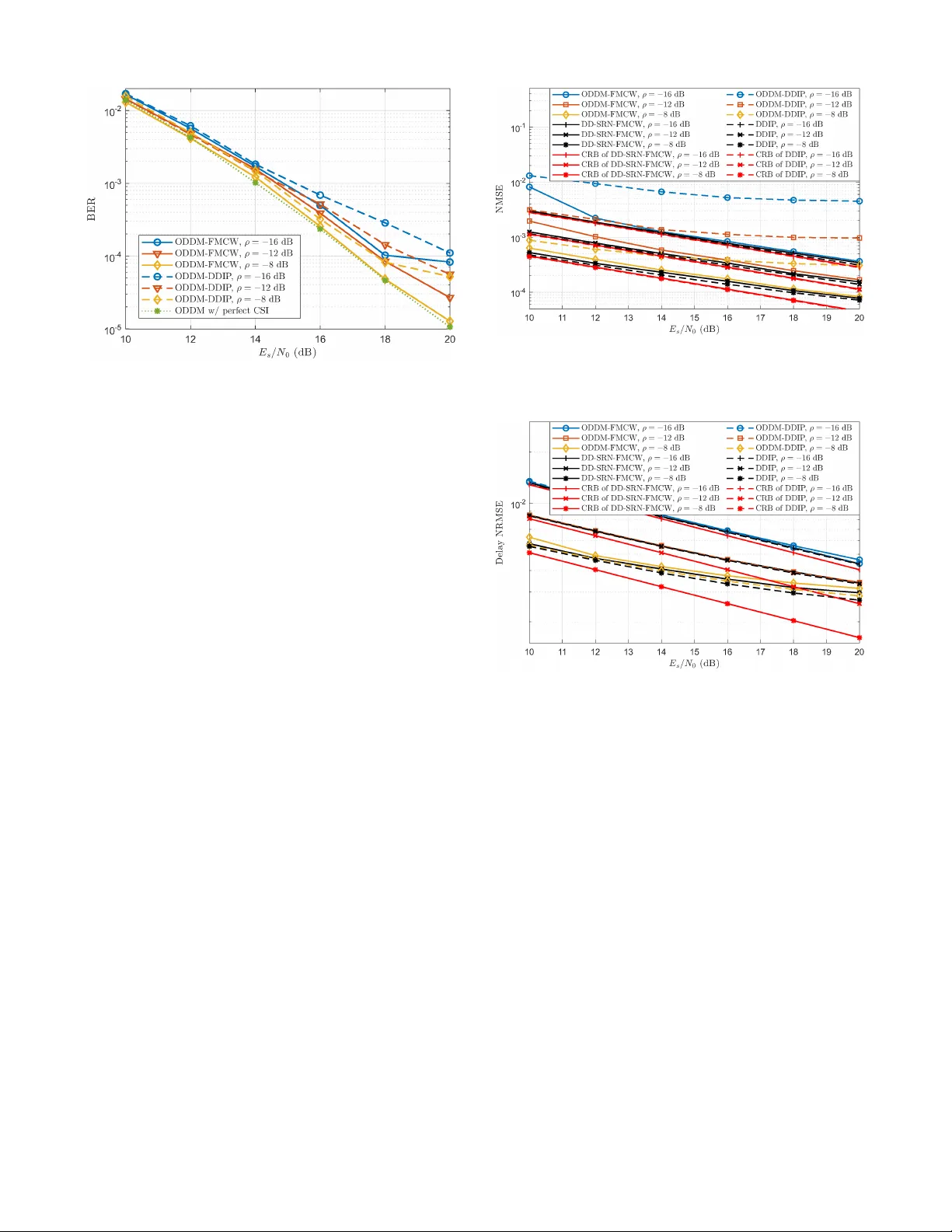
ACCEPTED FOR PUBLICA TION IN IEEE TRANSACTIONS ON WIRELESS COMMUNICA TIONS. 1 A No v el ISA C W a vef orm Based o n Orthogo n al Delay-Doppler Di vision Multiple xing with FMCW Kehan Huang, G rad uate Studen t Member , IEEE, Akram Sh afie, Memb er , IEEE, Min Qiu, Senior Membe r , IEEE Elias Aboutanios, Se nior Membe r , IEEE, and Jinhong Y uan, F e llow , IEEE, Abstract —In this work, we propose the orthogonal delay- Doppler (DD) division multiplexing (ODDM) mo dulation with frequency modulated continu ous wa ve (FMCW) (ODDM - FMCW) wa vef orm to enable integrated sensing and communi- cation (ISA C) with a low peak-to-a v erage power ratio (P APR). W e first propose a square-r oot-Nyquist-filtered FMCW (S RN- FMCW) wav ef orm to add ress limitations of con ve ntional lin ear FMCW wavef orms in ISA C systems. T o b etter int egrate with ODDM, we generate SRN-FMCW by embedding symbols in the DD domain, referred to as a DD-SRN-FMC W frame. A DD chirp compression receiv er is designed to obtain the ch annel response efficiently . Next, we construct the proposed ODDM- FMCW wav ef orm for ISA C by superimposing a DD-SRN-FMCW frame onto an ODDM data frame. A comprehensiv e performance analysis of the ODDM-FMCW wa v efo rm is presented, co vering peak-to-av erage power ra tio, sp ectrum, ambiguity function, and Cram ´ er -Rao bou nd f or delay and Doppler estimation. Nu merical results show that the proposed ODDM-FM C W wave for m delivers excellent ISA C p erf ormance in terms of root mean square error fo r sensing and bit er ror rate f or communications. Index T erms —ODDM , O TFS, integrated sensi n g and commu- nications (ISA C), F M CW , channel estimation, P APR I . I N T RO D U C T I O N Integrated sensing and commun ication ( ISA C) has emerged as a key f ocus ar ea in next-genera tion wire less network s, allowing more efficient use of frequency resou rces. Build in g upon a unified wa veform, ISA C systems aim to suppor t data transmission between co m munication no des while si- multaneou sly performing sensing tasks. W ith the potential to drive mu ltiple next-generation applications, ISAC is especially relev ant in hig h -mobility e nvironmen ts, including satellite an d vehicle-to-everything (V2X) comm unications [2 ]–[4] . T o ad dress the cha llen ges o f reliable comm u nications in high-m o bility environments, d elay-Dopp ler (DD) modulatio n schemes, such as or thogon a l time freq u ency sp a ce (O TFS) The work of K. Huang, A. Shafie, M. Qiu, a nd J. Y uan was supported in part by the Australian Research Council (ARC) Discov ery Proj ect under Grant DP220103596, in part by the ARC Linkage Project under Grant LP200301482, and in part by the Connecti vity Innov ation Network , Australi a. The w ork of M. Qiu was also supporte d in part by the SJT U ExploreX Funding under Grant SD6040004/153. This work has bee n presented in part at the 2025 IEE E Internat ional Conferenc e on Communica tions [1]. (Correspondi ng author s: Akram Shafie and Min Qiu.) K. Huang, A. Shafie, E. Aboutanios, and J. Y uan are with the School of Electric al Engineering and T elecommunicat ions (EET), Uni versity of New South W ales (UNSW), Sydney , NSW 2052, Australia (email: keha n.huang@unsw .edu.au; akram.shafie@un sw .edu.au; elias@i eee.or g; j.yuan@unsw .edu.au). M. Qiu was with the School of EET , UNSW , Sydney , NSW 2052, Australia, when this w ork wa s co nducted. He is no w with the Global Colle ge, Shanghai Jiao T ong Uni versi ty , Shanghai 200240, China (email: m in qiu@sjtu.e du.cn). modulatio n [5] a n d affine f requency division multiplexing (AFDM) modulatio n [6], have been prop osed to exploit chan - nel d i versity in the DD do main, offering enhanc e d r o bustness to doubly - selecti ve channels. Building on O TFS, the recently propo sed orthogon al DD division multiplexing (ODDM) mod- ulation introdu c es a prac tica l DD orthogon al pulse (DDOP) with low out- o f-band e missions (OOBE) while main taining sufficient biorthog onality at fine DD resolution for the gi ven signal ban dwidth an d time span [7], [8]. Alth ough initially designed for com m unications, the under lying DDOP share s similarities with pu lse-Doppler radar signals, highlightin g its potential for I SA C applications. Notab ly , ODDM and OTFS share the same DD domain information-b earing symbols, but the use of DDOP allo ws ODDM to directly em bed DD do - main symbo ls into continu ous-time wa veforms. The wa veform generation o f O TFS, on th e other hand, is based on the time- frequen cy ortho gonal pulse (TFOP), which doe s not align with the in herent operation of doubly selective chan nels [8 ], [9]. In this work, we in vestigate I SA C within the ODDM framework. Howev er , the propo sed I SA C desig n applies to both ODDM and O TFS b y con sidering the co rrespond ing input-o u tput relations. T o enable sen sin g and channel estimation , a DD-d omain impulse pilot ( DDIP) was propo sed for OTFS in [10 ], and later a d opted for ODDM in [8 ] , [1 1], [1 2]. DDI P is well- localized in the fast-time/de lay d imension, facilitating the effecti ve decouplin g of delay and Do ppler param eters [13] . Howe ver , it can have a h igh pe a k-to-average power ratio (P APR), leading to potential non- linear sig n al distortion and low power ef ficiency in practical transceiv ers. Recent stud ies h av e desig n ed DD-do main low-P APR pilots by spreadin g the pilot energy across mu ltiple pilot symbols. For instanc e , [14] introdu c ed the scattered p ilots, wh ere the placement of pilot symbols is carefully chosen to a v oid self- interferen ce. Howe ver , this placem ent relies on the frame size an d channel supp ort, makin g it less ro bust to practical systems. T o mitigate self-interference, orthogo nal seq uences, such as Zadoff-Chu (ZC) seq uence and c hirp sequence, h ave been employed [ 15]–[1 7]. In [15 ], a Z C-based spread pilot was propo sed, wh ic h require s an excessi ve guard interval. This is b ecause a cyclic extension is pad ded to utilize the cyclic ortho g onality of ZC sequences, an d the length of the sequence necessitates the span of the gu ard interval to pr e- vent interference with data symbols. Similarly , [17] proposed another ZC-ba sed p ilo t without g u ard in terval. Despite higher spectral efficiency , this design fails to fu lly exploit the cyclic orthog onality , which may c omprom ise sensing perf ormance. ACCEPTED FOR PUBLICA TION IN IEEE TRANSACTIONS ON WIRELESS COMMUNICA TIONS. 2 T o further impr ove spectr a l efficienc y , [18] intr oduced a su- perimpo sed rando m pilot and r ecovered the channel state using a minimum mean square error (MMSE) estimator . Howe ver , this app roach requir e s prior knowledge of the channel supp o rt, which is often u nav ailable fo r communication recei vers. While [15] and [ 17] consider ed fra c tio nal Doppler shifts, the afo rementione d pilot design s do not address th e off-grid sampling of both d elay and Do p pler shifts—an in herent aspect of ISA C systems. T o account for this, [19] proposed a chirp- based spread pilot a n d applied a root-MUSIC algo rithm f or DD estimation, but th e ideal p ulse assumed for O TFS is not realizable. Build ing on practical pu lses, [20 ] prop osed a 2D- chirp-b ased spre ad pilot. Nonetheless, the 2 D chirp sequence lacks ortho gonality , which can limit its sen sing perf ormance. Therefo re, designing a chann el-robust, lo w-P APR ISAC wa ve- form remains an open pr o blem. Frequency modulated contin uous wa ve (FMCW) is widely used in auto motive r adars for its simplicity and low P APR [13], [21]. Hence, the com bination of ODDM an d FMCW can potentially p r oduce low-P APR ISA C waveforms that are fully com patible with OTFS/ODDM technolog ies. [22 ] in- vestigated the symbol-level representatio n of FMCW sig nals within the O TFS framework. Ho we ver , con sidering practical continuo us-time signals, the combination of O TFS/ODDM and FMCW has not been well resear ched due to the fol- lowing ch allenges. Firstly , FMCW signals do not satisfy the Nyquist intersymbo l inter ference (ISI) criter io n with respec t to O TFS/ODDM signals, which can cause comp lica te d mutual interferen ce in ISA C systems [8], [2 2], [23]. Secon dly , with limited band width and a h ig h p ulse rep etition interval, the stretch pro cessing technique used in co n ventional FMCW radar receivers is susceptible to range- Doppler c o upling and range skew [1 3]. Finally , FMCW signa ls exhibit high OOBE, making them u nsuitable for pr actical com m unication system s. T o add ress the se challen ges, we pro pose an ISAC frame- work based o n a novel ODDM- FMCW wa veform. The main contributions o f the pa per are a s follows: 1 ) W e propose the square-ro ot Nyquist (SRN)-filtered FMCW (SRN-FMCW) wa veform to enable sensing and c h an- nel estimation with controlled ch irp co mpression side lo bes and reduced transmission overhead. T o support co existence with O DD M sy stem s, we intro duce the DD-domain e mbed- ded SRN-FMCW (DD-SRN-FMCW) waveform, which can be generated using an ODDM transmitter . Buildin g o n th e ODDM receiver , we further pro pose DD chirp compression to efficiently ob tain th e DD response (DDR) of the chann e l. 2 ) W e pro pose th e ODDM-FM CW wa veform for I SAC, where an ODDM data fr ame is transmitted with a superim- posed DD-SRN-FMCW frame. F or d ata-aided sensing (D AS) at the colloca te d sensing r e c ei ver , we introdu c e a sup er- resolution sensing algo rithm based on o r thogon al ma tc h ing pursuit (OM P) [24]. For join t channel estimation and data detection (JCEDD) at the communicatio n recei ver , we com - bine OMP and soft successi ve interference c a ncellation with minimum mean square error (SIC-M MSE) detector [2 5]. 3 ) W e p r esent a compr e hensive perform ance analysis fo r the pro posed DD-SRN-FMCW and ODD M -FMCW signals. First, a g ood approx im ation is gi ven for their P APR c o mple- T ABLE I I M P O RTA N T S Y M B O L S U S E D I N T H I S PA P E R . Symbol Meaning M , N Number of delay and Doppler bins, respect iv ely . a ( t ) , g ( t ) SRN pulse and Nyquist pulse. ǫ Chirp rate. c ( t ) , c a ( t ) Linear chirp and SRN-filtered chirp. c Discrete chirp sequenc e. ex , ce Linearly and cyclica lly extende d signal, respecti vely . X General ODDM frame or ODDM-FMCW frame. X c , X d DD-SRN-FMCW frame and ODDM data frame. ρ Chirp-dat a-po wer- ratio (CDPR). mentary c u mulative distribution func tio n (CCDF). Second, we characterize their power spectral density ( PSD) and highlight the dif ferences f rom a linear FMCW sign al. Additionally , th e ambiguity fu nction of the DD-SRN-FMCW signal an d the Cram ´ er-Rao bound (CRB) for delay and Dopple r estimation are deri ved, c o nfirming its strong sensing capability . 4 ) W e dem onstrate via simu latio ns that the pr oposed ODDM-FMCW wav eform offers significantly lower P APR than ODDM with a sup erimposed DDIP (ODDM-DDIP). Ow- ing to its robustness again st c h annel estimation error s, ODDM- FMCW con sistently outper f orms ODDM-DDI P in terms of bit error r ate (BER) at the communication receiver , approaching that of ODDM with perfect channel state inform ation (CSI). Moreover , lo w nor malized root m ean square error (NRMSE) in delay and Dopp ler estimation can be achieved at the sen sin g receiver . Notatio ns : ( · ) ∗ and ( · ) H denote the complex conju gate and Hermitian transpose, respe c ti vely . [ · ] † denotes the pseud oin- verse. F N denotes the normalized N -point DFT matrix. [ · ] N means mod ulo N . ⌊·⌋ means floo r . δ ( · ) denotes th e Dirac de lta function . k A k ou tputs th e 2-norm of matrix A . Denote the column- stacking vectorization of A ∈ C m × n by a = vec ( A ) , with in verse operatio n vec − 1 m × n ( a ) = A . gcd( · ) ou tputs the greatest c o mmon divisor . Th e impo rtant symbols and their definitions are summarized in T able I. I I . P R E L I M I NA R I E S A N D M O T I V AT I O N S In this work, we e xplore ISAC in a dynamic environment, as depicted in Fig. 1. W e co nsider an ISA C transmitter that transmits the propo sed ODDM-FMCW signal to a commu - nication receiver , while simultan eously using the same signal for mon ostatic sensing with a collocated sensing receiver . The ODDM-FMCW frame X is constructed by superimposing a DD-SRN-FMCW frame X c onto an ODDM data frame X d , where X c function s as b oth the sensing signal and channel estimation pilot. An ODDM transmitter is used to tran smit X . At both recei vers, the time-domain rec e i ved signal r ( t ) is first pro cessed by th e ODDM receiv er to o btain the receiv ed ODDM-FMCW frame Y . Then , DD ch ir p compression is perfor med to compu te the DDR D of th e chann el. For the collocated sen sin g receiver , a D AS algorithm is used to enable super-resolution sensing. For the com m unication re c e i ver , a JCEDD algorithm is used to perfo rm d ata detection. In the rest of th is section, we present preliminar ies for the ODDM-FMCW system introduced in the following section s. ACCEPTED FOR PUBLICA TION IN IEEE TRANSACTIONS ON WIRELESS COMMUNICA TIONS. 3 Communication Rx Echo (2-W ay) Sensing Channel 1-W ay Communication Channel JCEDD ˆ X d Digital Chirp Compression D c Y c r c ( t ) X c h c ( τ , ν ) ODDM Tx Operations X s ( t ) X d X c ODDM Rx Operations Y s ˆ h s ( τ , ν ) r s ( t ) D s ODDM Rx Operations h s ( τ , ν ) Collocated Sensing Rx ISAC Tx X d X c DAS Digital Chirp Compression Fig. 1. Considered ISAC scenario. W e begin with the doubly-selective channel. Next, we detail the simp lified/appro x imate implementatio n o f ODDM modula- tion [7]. W e then re view the linear FMCW radar waveform and its stretch -processing receiver . Additionally , we discuss c h irp compression , a r eceiv er techn ique employed in chirp- b ased pulsed radars. Finally , we high light challenges in app lying these standalone ODDM and FMCW systems to ISA C. A. Doub ly-Selective LTV Channel T o char a cterize signal pro pagation in Fig . 1, we adopt a doubly - selecti ve linear time-varying (L TV) ch annel model with P p o int scatterers. Each scatterer ha s com plex p ath coefficient α p , in itial pr opagation delay τ p , and velocity v p . W e d efine v p as the ch anging r ate of the propagation distance along the p -th p ath, yielding a time-varying pro p agation delay ˙ τ p ( t ) = τ p + v p c t , with c being the speed of light. F ollowing the Swerling 1 target model and short-time assumption [8] , [13], α p and v p remain constant d uring a r adar co herent pr o cessing interval, which is also the ODDM frame du r ation. Suppose the tra nsmitted p assband signal s pb ( t ) occupies a bandwidth B arou nd c a r rier f requency f c . When B ≪ f c , the received passband sign al can be expressed as 1 r pb ( t ) = P X p =1 α p s pb ( t − ˙ τ p ( t )) + z pb ( t ) , (1) where z pb ( t ) is the passband Gau ssian noise. Let s pb ( t ) = s ( t ) e j 2 π f c t denote the p assband of a linearly modulated baseband signal s ( t ) . Sub stituting into ( 1) gi ves r pb ( t ) = P X p =1 α p s ( t − ˙ τ p ( t )) e j 2 π f c ( t − τ p ) e j 2 π ν p t + z pb ( t ) , (2) where ν p = − f c v p c is th e Dop p ler shift of the p -th path. Assuming pe r fect carrier sync hronizatio n and the narrowband approx imation s ( t − ˙ τ p ( t )) ≈ s ( t − τ p ) , do wn-conversion o f r pb ( t ) by e − j 2 π f c t yields r ( t ) = P X p =1 h p s ( t − τ p ) e j 2 π ν p t + z ( t ) , (3) where h p = α p e − j 2 π f c τ p (4) 1 Although passband signals are real-v alue d, without loss of generali ty , we represent them as analyti c (complex) signals to streamline the deri v atio ns in this work. T his is justified under the narrowba nd assumption B ≪ f c . is the baseband channel coefficient of the p -th path, and z ( t ) is the baseband co mplex Gaussian noise. W e clarify that (3) takes the form of Bello’ s baseban d L T V channe l m odel [26], characterized by a DD-d omain spreading function: h ( τ , ν ) = P X p =1 h p δ ( τ − τ p ) δ ( ν − ν p ) . (5) In our ISA C scenario illustrated in Fig. 1, two doub ly-selectiv e channels are of in te r est: the echo sensing channel h s ( τ , ν ) an d the one-way com munication channel h c ( τ , ν ) . B. ODDM Modulatio n ODDM was pro posed for doubly -selectiv e chan nels as a DD-domain multicarrier mo dulation. I n this section , we detail the simplified/approx im ate ODDM implementation [7]. 1) ODDM T ransmitter: Con sider the transmission of M N symbols within nom in al bandwidth B = M T and transmission time N T . ODDM ar ranges the sy mbols X ∈ C M × N onto a DD grid w ith delay resolution ∆ τ = T M and Doppler resolution ∆ ν = 1 N T . At the tra n smitter , X is first con verted into the d elay-time (DT) domain by N -point IDFT to obtain X DT = X F H N . Then, X DT is vectorized to obtain the time - domain digital samples as s = vec( X DT ) , with its q -th element den oted by s [ q ] . Finally , the continuo us-time b aseband signal s ( t ) is g enerated by a ( t ) -based p ulse shaping [7] s ( t ) = M N − 1 X q =0 s [ q ] a t − q T M , (6) where a ( t ) is a squar e-root Ny quist (SRN) p ulse that serves as the subpulse of ODDM. T o accomm odate u nderspr e ad channels with maximum de la y spread τ max < T , ODDM adopts a fr ame-wise cyclic prefix (CP) with a du ration of τ max . 2) ODDM Receiver: At the ODDM receiver , the received baseband signa l r ( t ) is m atched filtered usin g a ( t ) and sam- pled at t = q T M for q ∈ { 0 , . . . , M N − 1 } , to o btain the time-dom a in r e ceiv ed sample vector r ∈ C M N × 1 . For the L TV channel in (5), the rec evied samples r [ q ] beco me [8] r [ q ] = P X p =1 h p 2 Q X d =0 e j 2 π k p ( q − l p − d ) M N g ( d + ⌊ l p ⌋ − l p ) T M × s [ q − ⌊ l p ⌋ − d ] M N ! + z [ q ] , (7) where l p = τ p M T and k p = ν p N T are the norma lized d elay and Dop pler shifts of the p -th path, respectively , g ( t ) = a ( t ) ⊛ ACCEPTED FOR PUBLICA TION IN IEEE TRANSACTIONS ON WIRELESS COMMUNICA TIONS. 4 a ∗ ( t ) is a ca usal sym metric Nyq uist pu lse cen tered at t = Q T M , and z [ q ] ∼ C N 0 , σ 2 z is the sampled no ise. Q is the half-span truncation length o f g ( t ) (in sym bol intervals) for practical implem e n tation. W e set Q = 20 so that the pulse support beyon d 2 Q T M is n egligible [7], [8 ] , [27] . Note that l p and k p can take fractio nal (off-grid) values. T o convert time-d omain samples r back to the DD d omain, the DT do main matrix is con structed as Y DT = vec − 1 M × N ( r ) . Then, N -p oint DFT is perfo rmed to obtain the receiv ed DD- domain ma tr ix as Y = Y DT F N . The symbol at th e m -th delay and n -th Doppler bin in Y is g i ven by [8] Y [ m, n ] = P X p =1 Y p [ m, n ] + Z [ m, n ] , (8) where Y p [ m, n ] = h p 2 Q X d =0 e j 2 π ( m − l p − d ) k p M N g ( d + ⌊ l p ⌋ − l p ) T M × N − 1 X ˜ n =0 φ ( ˜ n + k p − n ) ψ [ m, d, ˜ n ] X [ m − ⌊ l p ⌋ − d ] M , ˜ n is the signal compon ent correspond ing to th e p -th pa th , and Z [ m, n ] ∼ C N (0 , σ 2 z ) is the DD-do main sam p led noise. Here, φ ( n ) = 1 N N − 1 X n ′ =0 e j 2 π nn ′ N = 1 − e j 2 π n N 1 − e j 2 π N n (9) denotes the Dirichlet kern el, whereas ψ [ m, d, ˜ n ] = e − j 2 π ˜ n N , m − ⌊ l p ⌋ − d < 0 , 1 , 0 ≤ m − ⌊ l p ⌋ − d ≤ M − 1 , e j 2 π ˜ n N , m − ⌊ l p ⌋ − d > M − 1 , represents the CP-in duced phase ro tation. Leveraging the input-o u tput relation in (8), DDIP has b ecome the most con - sidered pilot design for c h annel estimation in O TFS/ODDM literature [3], [8], [10]–[12] , [2 8]. C. FMCW Radar and Str etch Pr ocessing FMCW rad a r is widely used in automotive application s due to its low complexity and energy efficienc y [13 ], [21 ] . In this section, we re view its signal model and highligh t the key differences fr o m co n ventional com munication systems. Consider a passband lin e ar FMCW sign al with N ch irps c ( t ) and a p ulse repetition interval (PRI) of T , gi ven by s c ( t ) = N − 1 X n =0 c ( t − n T ) . (10) Each chirp c ( t ) is defined as c ( t ) = ˙ c ( t )Π T t − T 2 , (11) where ˙ c ( t ) = e j 2 π ( f c + ǫ 2 t ) t (12) is an infinite- time linear chirp and Π T ( t ) deno tes a rectang ular window o f dur ation T . Here f c is the car r ier frequen cy and ǫ is the c hirp rate. c ( t ) has an instantaneous frequ ency o f d dt arg( c ( t )) = f c + ǫt and a total bandwidth of B = ǫT . As will be shown in Section V -B, s c ( t ) exhibits distinct spectral characteristics compared to communication signals. When con sid e ring th e passban d channel described in (1) in Section II-A, the r e ceiv ed FMCW signa l b ecomes r c ( t ) = P X p =1 α p N − 1 X n c ( t − nT − τ p ) e j 2 π ν p t + z pb ( t ) . (13) T o obtain th e chan nel’ s DDR from r c ( t ) , the FMCW radar receiver employs str etch pr ocessing (also kn own as dechirp- ing ) [13], [21], [29]. In particular, r c ( t ) is mixed with s c ( t ) to obtain the beat fr equen cy signal r b ( t ) = s c ( t ) r ∗ c ( t ) . Then, r b ( t ) is sample d with interval T M and reshap ed to form a rada r data matrix R b ∈ C M × N , gi ven b y R b [ m, n ] = r b nT + m T M = ( P P p =1 h ′ p R b,p [ m, n ] , m T M ≥ τ p , P P p =1 h ′ p R b,p [ m, n ] e j 2 π ǫT τ p , otherwise , (14) where h ′ p = α p e j 2 π τ p ( f c − ǫ 2 τ p ) (15) is the channel co efficient for the p -th path and R b,p [ m, n ] = e j 2 π T M ( ǫτ p − ν p ) m | {z } fast-time varying e − j 2 π T ν p n | {z } slow-time varying (16) is the correspond ing fast-slow time response. 2 Finally , a 2D- DFT yields the channel DDR as D b = F M R b F N . By inspe c tin g (16), it ca n be inf e rred that the fast-time an d slow-time com ponents o f R b,p [ m, n ] will appear as separable sinc profiles center ed at τ p − ν p ǫ and ν p in D b , respecti vely . The slo w-time sinc dire c tly cor respond s to the Doppler shif t ν p . Howe ver , the fast-time sinc gives τ p − ν p ǫ , wh ich is the true delay τ p distorted by the Doppler shift. This phenom enon is kn own as range-Doppler coupling [13], [ 29]. In ad dition, the extra term e j 2 π ǫT τ p in the second case o f (14) introduces a discontinu ity in ph ase, giving r ise to the range skew e f- fect [1 3]. These issues beco me m ore p r onoun ced when the allocated time ( T ) and bandwidth ( B ) are relatively limited, thereby restricting FMCW rad a r p e r forman ce u n der typ ical commun ication constraints. From a n ISAC stand point, com munication receivers re q uire the baseband channel c o efficient h p as in ( 4) f or sym bol detection, wh ose ph ase depe nds linearly on τ p . In c o ntrast, th e FMCW channe l c o efficient h ′ p in (1 5) contains a distinct p hase term proportio nal to τ 2 p . According ly , u sing FMCW ra d ar f o r baseband channel estimation requ ires a nonlinear con version from h ′ p to h p , which can a mplify channel estimation errors. 2 “fa st time” and “slow time” follo w radar terminol ogy , where “fast time” refers to samples within a PRI and “slow time” refe rs to va riation s acro ss PRIs [13]. They align with the concepts of delay and time in O TFS/ODDM. ACCEPTED FOR PUBLICA TION IN IEEE TRANSACTIONS ON WIRELESS COMMUNICA TIONS. 5 (a) T B = 64 . (b) T B = 256 . Fig. 2. Delay ambiguity (chirp compression output ) of chirps. D. Chirp-based Pulsed Radar and Chirp Compression Pulse compr ession is a com mon r eceiv er tech n ique for pulsed radars. I t is also termed chirp compression when chirp signals are used as radar pulses [ 2 9]. W e explo r e chirp compression in this work since it shares similarities with the matche d filterin g operation s in O TFS/ODDM and single- carrier (SC) system r eceiv ers. Chirp co mpression r elies on the fact that th e a utocorre latio n of the ch irp signal c ( t ) in (11) yields a sinc- like pulse. T o understan d this, we first look into the ideal c hirp compr e ssion output, g i ven by the crosscor relation between the infinite-time chirp ˙ c ( t ) in (12) a nd the finite-time chirp c ( t ) in (11 ) A ˙ c,c ( τ ) , Z ∞ −∞ ˙ c ( t ) c ∗ ( t − τ ) dt = e j 2 π ( f c − ǫ 2 τ ) τ Z T 0 e j 2 π ǫτ t dt = T e j 2 π ( f c − ǫ 2 τ ) τ e j π ǫτ T sinc( ǫT τ ) , ( 1 7) which is e ssen tially the ideal delay ambiguity fun ction of a chirp signal. Since (17) is a sinc-type functio n of delay , its sharp mainlobe admits straig htforward delay estimation . Howe ver , A ˙ c,c ( τ ) assumes a n ideal infinite-time chir p ˙ c ( t ) . In practice, finite-time chir ps suffer pulse degradation, esp e - cially with a limited tim e - bandwidth produ ct T B . T o show this, we now consider the autocorrelation o f c ( t ) , written as A c ( τ ) , Z ∞ −∞ c ( t ) c ∗ ( t − τ ) dt = e j 2 π ( f c − ǫ 2 τ ) τ Z min( T ,T + τ ) max(0 ,τ ) e j 2 π ǫτ t dt. (1 8) Fig. 2 comp ares A ˙ c,c ( τ ) (blue curve) and A c ( τ ) ( o range curve) using the paramete r s in Section VI ( the gree n curve will be d iscussed later in Section III-A). Compared to the ideal A ˙ c,c ( τ ) , A c ( τ ) exhibits an e le vated, br oadened sidelobe floor, which becomes more pro nounce d for lower T B . T his directly follows from the τ -depen dent integration bound s in (18) and, in the f requency domain, correspon ds to the classical F r esnel ripple [30 ]. In ad dition, A c ( τ ) lac ks a closed- form expression, hindering superresolu tion sensing. Most impor- tantly , the zeros of A c ( τ ) d o not align with th ose of the sinc function . T hat is, the Nyquist ISI criterio n may not b e satisfied, which comp lica tes the mutu al inte r ference between sen sing and communica tio n signals in an I SA C context. E. Challenges and Motivations The ODDM system discussed in Section II-B is designed for data transmission over do ubly-selective chan nels. Althoug h the wide ly ado pted DDIP shows pr omising cha nnel estimation and sensing perfo rmance [10], [12], [28], it exhibits hig h P APR an d low ene rgy efficiency . Conv ersely , while the FMCW wa veform in Section II-C provides unit-P APR sensing capab il- ity , it faces challenges in the integration with communication systems, in cluding ran ge-Dopp ler co upling, r a n ge skew , and error am plification. Moreover, p assband FMCW systems may not be dire c tly com p atible with baseband modu latio n systems. The ch irp com p ression method describ ed in Section II -D reveals a poten tial solution to these challenges. In particular, chirp compression tr eats ea c h chir p as an individual radar pulse a n d theref ore better align s with pulse-b ased modu lation schemes such as OTFS/ODDM and SC. Th is, howe ver , in- troduces new d iffi culties, includin g prono unced sidelobes, a lack of clo sed -form e xpression, and violation of the Nyquist ISI criterion. These limitations motivate the DD-SRN-FMCW sensing wa veform we pro pose in the next section. I I I . F RO M L I N E A R F M C W T O D D - S R N - F M C W In this sectio n, we pro pose the DD-SRN-FMCW wav e- form to overcome the limitations of linear FMCW in ISAC applications highlighte d in Section II- E. W e first design a SRN-filtered chirp, fo llowed by the SRN-FMCW wav eform incorpo rating mu ltip le c h irps. Finally , w e introdu ce DD-SRN- FMCW to achieve co mpatibility with the O D D M framework. A. SRN-F ilter ed C hirp with Chirp Compr ession As discussed in II- D, the sinc -type delay ambigu ity fu nction A ˙ c,c ( τ ) in (17) is n o t achievable with the practical finite- time chirp c ( t ) . Howe ver , we no te that the sinc-type delay ambiguity function can b e loca lly ac h iev ed by transmitting an extended ch ir p signal, e. g., c ex ( t ) = ( ˙ c ( t ) , t ∈ ( − τ max , T + τ max ) , 0 , otherwise . (19) Then, th e cro sscorrelation between c ex ( t ) and c ( t ) , gi ven by A c ex ,c ( τ ) = R ∞ −∞ c ex ( t ) c ∗ ( t − τ ) dt , satisfies A c ex ,c ( τ ) = A ˙ c,c ( τ ) for delays τ ∈ ( − τ max , τ max ) . That is, Fresn el-ripple sidelobes can be a v oided within a finite delay interval. Howe ver , c ex ( t ) extends in both time and frequency com- pared to c ( t ) , taking more spectral resou rces to sup port dispersive chan nels with large delay spreads. Ther e fore, we now lev erage the sampling theor em to redu ce the tran smission ACCEPTED FOR PUBLICA TION IN IEEE TRANSACTIONS ON WIRELESS COMMUNICA TIONS. 6 overhead. T o begin with, we samp le ˙ c ( t ) at t = m T M for m ∈ Z to obtain the discrete chirp seq uence ˙ c [ m ] = e j 2 π f c T M m + ǫT 2 2 M 2 m 2 . (20) Inspired b y the sinc-type d e la y amb iguity in (1 7), we establish the following Lemma for ˙ c [ m ] : Lemma 1. If ǫT 2 M ∈ Z an d gcd ǫT 2 M , M = 1 , then ˙ c [ m ] satisfies the zer o linear autocorr elation ( ZLA) pr op erty: M − 1 X m =0 ˙ c [ m ] ˙ c ∗ [ m + ζ ] = M δ [ ζ ] , ( 21) for ζ ∈ Z . Pr o o f: The p roof is gi ven in Appendix A. Giv en the ZLA prop erty in Lemma 1, the requiremen t o f linear extension of the linear chirp ˙ c ( t ) can be r e la xed to the linear extension o f the discrete chirp sequ ence ˙ c [ m ] , which av oids the tra n smission overhead in b a ndwidth. Based on Lemma 1, we furth er relax the requ irement of linear extension to cyclic extension by establishing the fo llowing prop osition. Proposition 1. When the th ree con ditions ( a) ǫT 2 M ∈ Z , (b) gcd ǫT 2 M , M = 1 , and (c) f c T + ǫT 2 2 ∈ Z hold , the discr ete chirp sequence c [ m ] = ˙ c [ m ] , ∀ m ∈ { 0 , . . . , M − 1 } satisfies the zer o cyclic autocorr elation (ZCA) pr operty: M − 1 X m =0 c [ m ] c ∗ [ m + ζ ] M = M δ [ ζ ] M , (22) for ζ ∈ Z . Pr o o f: The p roof is gi ven in Appendix B. Proposition 1 in dicates that the discrete chirp seq uence c [ m ] can satisfy the ZCA pr operty in (22) by attachin g a cyclic prefix (CP) a n d a cyclic suffix (CS). While this section considers a single chirp, the restriction fr om linear to cyclic extension is most u seful for a ch irp train , where each chirp naturally reu ses its n eighbo r s as the CP and CS. The next subsection con structs a multi-ch ir p waveform th at exploits the ZCA property to r educe the transmission overhe ad in time. Remark 1 . Most c ommunicatio n systems can be de scribed by convolution operations, wher e th e channel r esponse and modulatio n pulse ar e strictly causal, making it possible to omit CS. Chirp comp r ession, however , reli es on co rr e la tion, whic h is a non-c a usal operation. Therefor e, a CS of length M is r equir ed to a ccommoda te such non-causality . By inspecting the conditions in Pro position 1, we can g et a trivial set of chirp p a rameters f or all even M , given by f c = 0 and ǫ = M T 2 . I nterestingly , if we substitute th ese pa rameters back into the linear FMCW signa l s c ( t ) in (1 0), it will result in a delay resolution of ∆ τ = T M and a Do ppler resolution of ∆ ν = 1 N T , wh ic h matches the DD resolution o f the ODDM signal discussed in Section I I -B. Substituting these p arameters into (20), we o btain the f ollowing coro llary . Corollary 1. The discr ete chirp sequ ence c ∈ C M × 1 with its m -th element given b y c [ m ] = e j π m 2 M , m ∈ { 0 , . . . , M − 1 } , (23) has the ZCA p r op erty in (2 2) for a ll even M . W e then use c to construct the SRN-filtered chirp c a ( t ) = M − 1 X m =0 c [ m ] a t − m T M . (24) Throu g h the usage of SRN pulse a ( t ) , c a ( t ) is naturally com- patible w ith baseban d modu la tio n schemes, includin g ODDM. More d etails o n the integration with ODD M will be discussed in Section III-C. On the o ther han d, accordin g to the ZCA proper ty in Proposition 1 , we can cyclically extend c a ( t ) to achieve a concise form of the delay ambiguity fu nction. Thus, we construct the c yclically e xtended SRN-filtered chirp as c a,ce ( t ) = 1 X n = − 1 c a ( t − nT ) , (25) where a CP c a ( t + T ) and a CS c a ( t − T ) are attached. Then , the crosscorr e lation between c a,ce ( t ) an d c a ( t ) is co mputed as A c a,ce ,c a ( τ ) , Z ∞ −∞ c a,ce ( t ) c ∗ a ( t − τ ) dt = M Z ∞ −∞ a ( t ) a ∗ ( t − τ ) dt = M g ( τ ) , (26) for delay shifts τ ∈ ( − T , T ) . That is, c a ( t ) has a delay ambiguity function in th e shape of th e Nyquist pu lse g ( τ ) . An example of A c a ( τ ) (gr een curve) is plo tted in Fig. 2, where we u se a squar e-root-r aised-cosine (SRRC) pulse for a ( t ) . Compared to A c ( τ ) o f a practical linear chir p, the sidelobes of A c a ( τ ) are significantly lower throu gh the usage of the SRRC p ulse. In ad dition, g ( τ ) na tu rally satisfies the Nyquist ISI criterion, facilitating ISA C wa vefo r m d e sign. B. SRN-F ilter ed FMCW T o further achie ve Doppler resolution, we use c a ( t ) as the radar pulse and define th e baseban d SRN-FMCW signal as s c a ( t ) = N − 1 X n =0 c a ( t − nT ) . (27) Notably , s c a ( t ) can be seen as a pulse-Dop pler radar sign al with a 100% d uty cycle. Ex c ept for the first ( n = 0 ) and last ( n = N − 1 ) SRN-filtered chirp pulses, th e ( n − 1) -th and ( n + 1) - th pulses naturally work as the cyclic extension of the n -th pulse c a ( t − nT ) . As a r esult, only a framewise CS and CP are required, y ie ld ing s c a ,ce ( t ) = N X n = − 1 c a ( t − nT ) . (28) An example of the transmitted sequence of th e SRN-FMCW signal s c a ,ce ( t ) inc luding a CP and a CS is given in the m iddle of Fig. 3 , where l max ≥ τ max M T is the CP length. The gr e en rectangles repr esent rand om ODDM data symb ols, wh ereas ACCEPTED FOR PUBLICA TION IN IEEE TRANSACTIONS ON WIRELESS COMMUNICA TIONS. 7 l max CP CS Payload/Effective Signal M M M M M M M M M M M M ODDM SRN-FMCW DD-SRN-FMCW Fig. 3. Time-d omain transmitt ed sequence s: ODDM, SRN-FMCW , and DD-SRN-FMCW . ( M = 8 , N = 4 ) the b lue rectang les—shown in v arying shad es—represent the discrete chirp sequence with a deter m inistic ph ase sweep. W e now dem o nstrate how the DDR of a dou bly-selective channel can be ob tained u sing SRN-FMCW . Substituting (27) to (3), the recei ved SRN-FMCW signal can be e xpressed as r c a ( t ) = P X p =1 h p N X n = − 1 c a ( t − τ p − nT ) e j 2 π ν p ( t − τ p ) + z ( t ) . (29 ) Then, c a ( t ) -based chir p comp r ession is perfo rmed on r c a ( t ) . After critical sampling and reshaping, the r adar data matrix R c a ∈ C M × N is obtained with M fast-time bins a n d N slow- time bins, whose ( m, n ) -th elemen t is given by R c a [ m, n ] = P − 1 X p =0 h p e j 2 π k p n N 2 Q X d =0 g ( d + ⌊ l p ⌋ − l p ) T M × M − 1 X ˜ m =0 e j 2 π ( ˜ m − l p − d ) k p M N c [ ˜ m − m ] M c [ ˜ m − ⌊ l p ⌋ − d ] M , ( 30) which is essentially the fast-slow time response of the chan nel. Finally , the channel DDR is computed by a row-wise DFT : D c a = R c a F N , with its ( ˙ m, n ) -th element gi ven by D c a [ ˙ m, n ] = P X p =1 h p φ ( k p − n ) 2 Q X d =0 g ( d + ⌊ l p ⌋ − l p ) T M × M − 1 X m =0 e j 2 π ( m − l p − d ) k p M N c [ ˜ m − ˙ m ] M c [ ˜ m − ⌊ l p ⌋ − d ] M . (31) By inspecting (3 1), we can see th a t each path’ s response exhibits a Nyq uist-shaped profile g ( · ) in delay and a Dirichlet- kernel-shaped profile φ ( · ) in Doppler . C. DD-Dom a in Emb edded S RN-F ilter ed FMCW This section presents DD-SRN-FMCW , an ef ficient DD- domain imp lem entation of SR N-FMCW , to achieve compati- bility with ODDM. W e note that the SRN-FMCW signal s c a ( t ) in ( 2 7) is equiv alent to the time-domain rep resentation of an ODDM fr ame X c ∈ C M × N , with its ( m, n ) -th sym b ol being X c [ m, n ] = ( √ N E c c [ m ] , n = 0 , 0 , otherwise , (32) where we intro duced E c = E t [ s c a ( t )] to r epresent the time- domain chirp power . That is, s c a ( t ) in (27) can be gene r ated by embed ding symbols in the DD d omain as (3 2), followed by ODDM transmitter op erations in Section II-B1. W e refer to X c as the DD - SRN-FMCW frame. T o f u rther integrate DD-SRN-FMCW with the ODDM receiver , we now intr oduce DD chirp compression. L e t Y c ∈ C M × N denote the received DD- SRN-FMCW frame after the ODDM transmitter , cha n nel, and r eceiv er ope rations. Substi- tuting (32) into (8 ), the ( m, n ) -th element of Y c is Y c [ m,n ] = P X p =1 h p φ ( k p − n ) 2 Q X d =0 e j 2 π ( m − l p − d ) k p M N × g ( d + ⌊ l p ⌋ − l p ) T M c [ m − ⌊ l p ⌋ − d ] M . (33) Then, chirp compression is per formed in th e DD d omain as D c [ ˙ m, n ] , M − 1 X m =0 c [ m − ˙ m ] M Y c [ m, n ] . (34) Direct algebra shows tha t (34) reduces to (31), y ielding th e same DDR expression. Compared to the direct c a ( t ) -based ch irp com pression in Section III -B, the DD chirp compression by (33) and (3 4) is decomp o sed into two cascaded stages: first matche d filtering with the SRN pu lse a ( t ) , then correlatio n with the d iscrete chirp sequenc e c . As the first stage is part of ODDM r eceiv er operation s, DD chirp co m pression can be re a dily implemen ted using the ODDM receiver , followed by an M -point corre lato r . Furthermo re, as the cor relation step is perf ormed in th e DD domain, we can exploit the DD quasi-per io dicity: when the Doppler shift is absent ( k p = 0 ), samp les from th e n = 0 Doppler column are per iodic along the delay d imension, as seen fr om (8). Since the c yclicity fo r c is gua r anteed, we can waive the time- domain CS in DD-SRN-FMCW to better align with ODDM. From th e DD pilot d esign p erspective, this also means the cyclic orthogonality of c can be exploited witho ut a d e dicated cyclic extension , makin g DD - SRN-FMCW dif - ferent from other orthog onal-sequ e n ce-based pilots [15] , [17] , [19]. Th e transm itted sequences o f ODDM, SRN-FMCW , and DD-SRN-FMCW are co mpared in Fig. 3. DD- SRN-FMCW requires only a CP and alig ns with the ODDM frame structur e. I V . P R O P O S E D O D D M - F M C W S Y S T E M F O R I S AC In this section, we propose ODDM-FMCW for ISA C. W e first intr o duce the ODDM-FMCW waveform by emb edding DD-SRN-FMCW in to an ODDM frame alo ngside data sym- bols. T h en, we discuss the receiver signal p rocessing schem es. ACCEPTED FOR PUBLICA TION IN IEEE TRANSACTIONS ON WIRELESS COMMUNICA TIONS. 8 Fig. 4. DD frame structure for ODDM-FMCW signals. A. ODDM-FMCW W aveform T o suppor t ISA C opera tion in Fig. 1, th e ODDM-FMCW frame X is con structed by superimp o sing a DD-SRN-FMCW frame X c onto an ODDM data fra me X d ∈ A M × N , i.e., X = X c + X d , (35) where each element of X d is drawn from a constellation set A for d ata modulatio n. Fig. 4 illustrates th e O D DM - FMCW frame struc ture. Ac c o rding to (32 ), the n = 0 Do ppler column is occu pied b y X c , used as the pilo t fo r both channel estimation and sensing. T he remaining column s are filled with data symbols X d , used for co mmunicatio n . No gu a r d inter val is allocated between DD-SRN-FMCW sym b ols an d ODDM data symbols to a v oid spectral ef ficiency loss. Giv en the linear tr a nsformation between DD dom ain and time domain , (3 5) co rrespon d s to a time-do main superimposed signal s ( t ) = s c a ( t ) + s d ( t ) , (36) where s c a ( t ) is the DD-SRN-FMCW signa l and s d ( t ) is the ODDM data signal. W e define the chir p-data-p ower-ratio (CDPR) as ρ = E c /E s , with ch irp power E c = E t [ s c a ( t )] and data power E s = E t [ s d ( t )] . By tuning ρ , on e can tr a de off sensing accura cy against c ommunic a tio n BER. The ODDM transmitter o p erations are perform e d on X to generate the baseband ODDM-FMCW signal. After propaga- tion through the ISAC channel an d ODDM receiv er oper ations, the received frame Y is o btained by (8). Given that no guard interval is employed, iterative inter ference cancellation is employed at bo th th e collocated sen sing receiver and the commun ication recei ver . For the co llocated sensing receiv er , a D AS algor ithm is used to enab le super-resolution sensing. For the communicatio n recei ver , a JCEDD algorithm is used to perfo rm data de tection. I n the following sections, we deta il these algorithms one after the oth er . B. Data-A ided Sen sing at Colloca ted Sensing R e ceiver D AS is p erformed at the collocated sensing r eceiv er to esti- mate the DD p arameters of th e c hannel paths. W e improve the OMP algor ith m [24] with gr id ev olution for low-complexity and super-resolution sensin g . The algorith m successively esti- mates the parameters n ˆ h p , ˆ l p , ˆ k p o for path p ∈ { 1 , . . . , P max } with P max being a pr edefined maximum path number, where grid evolution is p erformed as an inn er loop to refin e the DD re so lution. T he signal comp onents fr om the previously estimated paths are subtracted from the received signal to cancel their interference. Let ∆ Y p denote the path canc e llation residual before the estimation of the p -th p ath, co mputed by ∆ Y p = Y − p − 1 X p ′ =1 ˆ h p ′ a ˆ l p ′ , ˆ k p ′ . (37) W e have ∆ Y 1 = Y befo re estimating the first p ath. D u e to the h igh p rocessing gain of the DD-SRN-FMCW comp onent, we can comp ute the residual DDR ∆ D p by su bstituting ∆ Y p to (34). The highest response in ∆ D p giv es the integer DD shifts n ˆ l (0) p , ˆ k (0) p o . Th en, we perf orm OMP on a virtual g rid Λ with ev olving DD resolutio n. In particular, f or the ℓ -th grid ev olution, a matchin g pursuit is per formed as arg max ˆ l ( ℓ ) p , ˆ k ( ℓ ) p ∈ Λ ( ℓ ) a ˆ l ( ℓ ) p , ˆ k ( ℓ ) p H vec (∆ Y p ) 2 a ˆ l ( ℓ ) p , ˆ k ( ℓ ) p 2 , (38) where a ˆ l p , ˆ k p ∈ C M N × 1 denotes the atom, i.e., the noise- less response pro duced by a unit-g ain path at delay ˆ l p and Doppler ˆ k p , computed by (33). T he virtual grid Λ ( ℓ ) for the ℓ -th evolution is defined to be cen tered at the last-evolution estimates n ˆ l ( ℓ − 1) p , ˆ k ( ℓ − 1) p o with a halved DD resolution. Af- ter evolving the v ir tual gr id L times, the final estimatio n n ˆ l p , ˆ k p o = n ˆ l ( L ) p , ˆ k ( L ) p o lies on a refined DD grid Λ ( L ) with spacings reduced by a factor of 2 −L . After refin ing the DD estimates o f the p -th path b y grid ev olution, the coefficients of all pr eviously estimated path s are updated by least square s [2 4]: h ˆ h 1 , . . . , ˆ h p i T = h a ˆ l ( L ) 1 , ˆ k ( L ) 1 , . . . , a ˆ l ( L ) p , ˆ k ( L ) p i † vec ( Y ) . (39) The successi ve path estimation continues until P max is reached or k ∆ Y p k 2 stops decreasing, and we den ote the resulting number of estimated path s by ˆ P ≤ P max . W e sum marize the OMP algorithm with gr id e v olution in Algorithm 1. The OMP algo rithm described above treats superimp osed data sy m bols as noise. Howe ver , since the data sy mbols are k nown to th e c ollocated sensing receiv er , the channel distorted c ompon e nt of X d can be comp uted by (33) using the estimated ch annel p a rameters an d subtrac ted from Y to reduce interfe r ence from d a ta. After th at, OMP with p ath cancellation is emp loyed again to ach ieve b etter DD estimates. This process is iterated to progr essi vely refin e the estimation, as summarized in Algorithm 2 . Here we derive the c o mplexity o rder of th e D AS algor ithm, which o perates by iterativ ely cancelling the d ata comp onent and refining the cha n nel parameters via an OMP-b a sed sub- routine. W ithin each D AS itera tio n, the OMP-based subroutine estimates the c h annel parameters path b y path. For each path , coarse delay and Dopp ler e stimates are first obtained by ACCEPTED FOR PUBLICA TION IN IEEE TRANSACTIONS ON WIRELESS COMMUNICA TIONS. 9 Algorithm 1 OMP with Grid Evolution 1: input: Y , c , P max . 2: initialize: p ← 0 . 3: repeat 4: p ← p + 1 . 5: Obatin ∆ Y p by (37). 6: Obatin ∆ D p by substituting ∆ Y p to (34). 7: Obatin n ˆ l (0) p , ˆ k (0) p o by the highest re sp onse in ∆ D p . 8: for ℓ = 1 , . . . , L do 9: Construct Λ ℓ based on n ˆ l ( ℓ − 1) p , ˆ k ( ℓ − 1) p o . 10: Obatin n ˆ l ( ℓ ) p , ˆ k ( ℓ ) p o by (38). 11: end f or 12: ˆ l p ← ˆ l ( L ) p , ˆ k p ← ˆ k ( L ) p . 13: Update n ˆ h 1 , . . . , ˆ h p o by (39). 14: until p = P max or k ∆ Y p +1 k 2 ≥ k ∆ Y p k 2 . 15: ˆ P ← p . 16: output: n ˆ h p , ˆ l p , ˆ k p o for p ∈ { 1 , . . . , ˆ P } . Algorithm 2 Data-Aid ed Sen sing 1: input: Y , c , X d , P max . 2: initialize: ˆ Y c ← Y . 3: for i = 1 , . . . , I DAS do 4: i ← i + 1 . 5: Estimate the channel by ap plying Algor ithm 1 to ˆ Y c . 6: Estimate ˆ Y d by substituting X d to (8). 7: ˆ Y c ← Y − ˆ Y d . 8: end for 9: output: n ˆ h p , ˆ l p , ˆ k p o for p ∈ { 1 , . . . , ˆ P } . locating th e ma ximum o f th e resid u al DDR ∆ D p in ( 34). The circu lar correlation in (3 4) has an ef ficient FFT -based implementatio n, wh ich has a complexity o f O ( N M lo g 2 M ) . Then, matching p u rsuit as in (38) is per formed to refine the estimates with the grid ev olving L times, incurr in g a complexity of O ( L M N ) . After estimatin g the dela y and Doppler of th e p -th path , the coef ficients of the first p paths are updated by (39 ) with complexity O ( p 3 + M N p 2 ) , which sum s to O ( ˆ P 4 + M N ˆ P 3 ) over all ˆ P paths. There- fore, the total co mplexity o f the propo sed DAS algo rithm is O I DAS ˆ P N M log 2 M + L + ˆ P 2 + ˆ P 4 . No tably , ˆ P is typically small in sparse doub ly-selective chann els. The DDR-based coarse estimation sign ifica n tly sh r inks th e can - didate atom diction ary , while the subsequen t grid ev olution dynamica lly r e fin es this compact dictio nary to achieve h igh estimation accuracy without incurring excessi ve comp u tational complexity . C. Joint Channel Estimation a nd Data Detection a t Commu- nication Receiver Since both X d and CSI are unknown to th e comm unication receiver , we perform JCEDD by comb ining the modified OMP algorithm with the sof t SIC-M MSE d etector [25 ], which offers superior BER compare d to other co mmon d etectors like message pa ssing and iterative maxim um ra tio comb ining [1 1]. Fig. 5. Construction of a s ub-chan nel m atrix for SIC-MMSE. W e first brief the so ft SIC-MMSE detecto r assuming per- fect CSI, which perf orms low-complexity M MSE eq ualiza- tion using sub- channel matric e s. In the original SIC-MMSE algorithm [25] , eac h time-do main sample s [ q ] is associated with a fixed- length sp reading vector g ′ q ∈ C ( l max +2 Q +1) to capture its channel r esponse. T hen, a sub-chann el matrix G ′ q ∈ C ( l max +2 Q +1) × (2 l max +4 Q +3) is constru cted around g ′ q to cover the channe l respo nse relevant to s [ q ] and the in terfering samples. Th e relation be tween g ′ q , G ′ q , an d the full chann el matrix G is illustrated by the top two g raphs in Fig . 5. In this paper, we use a modified sub - channel matrix con - struction meth o d to ad aptively reduce the size o f G ′ q . In particular, we collapse the zer o elemen ts in g ′ q to obtain a dense spreading vector g q ∈ C L g , where L g ≤ min { l max + 2 Q + 1 , P (2 Q + 1) } is a co nstant rep resenting the numb er of non- zero elem ents in g ′ q . The corresp o nding sub -channel matrix G q ∈ C L g × (2 l max +4 Q +3) is constructed with height L g . This mo dification is illustrated by the bo tto m grap h in Fig. 5. It can be infer red th at th e size re duction to L g is pron ounced for sparse chan nels with large delay spreads, which is precisely the regime co nsidered in ou r ISA C mode l. Based on G q , we can define a sub -input-o utput relation for each s [ q ] to on ly in clude the chann el distorted com ponen ts of s [ q ] itself an d the interfering samples, allowing MMSE equalization with small sub-chan nel matrices. In practical implementatio n, interfer ence can cellation is used to efficiently express the sub- input-ou tput relation [25]. L e t ∆ r = r − G ˆ s denote the r esidual interferenc e plu s no ise vector, where ˆ s is th e a prio ri me an o f the transmitted sequence s . For each sample ˆ s [ q ] , we express the estimated received vector as ˜ r q = ∆ r q + g q ˆ s [ q ] , with ∆ r q being th e po r tion of ∆ r corr espondin g to g q . Then, sample-by -sample soft MMSE equalizatio n can be perform ed as ˜ s [ q ] = g H q G q V q G H q + σ 2 z − 1 ˜ r q , where V q is the correspondin g a priori e r ror cov ariance. ACCEPTED FOR PUBLICA TION IN IEEE TRANSACTIONS ON WIRELESS COMMUNICA TIONS. 10 Algorithm 3 Soft SIC-MMSE with Perfect C SI 1: input: Y , G , σ 2 z , A . 2: initialize: ˆ X ← 0 M × N , ˆ s ← 0 M N . 3: for i = 1 , . . . , I DET do 4: i ← i + 1 . 5: for m = 0 , . . . , M − 1 do 6: ∆ r ← r − G ˆ s . 7: ˜ s m ← 0 N . 8: for ˙ n = 0 , . . . , N − 1 do 9: q ← ˙ nM + m . 10: Extr act g q and G q from G . 11: ˜ r q ← ∆ r q + g q ˆ s [ q ] . 12: ˜ s m [ ˙ n ] ← g H q G q V q G H q + σ 2 z − 1 ˜ r q . 13: end f or 14: ˜ x m ← F N ˜ s m . 15: for n = 0 , . . . , N − 1 do 16: ˆ X [ m, n ] ← η A ( ˜ x m [ n ]) . 17: end f or 18: { ˆ s [ ˙ nM + m ] } N − 1 ˙ n =0 ← F H N ˆ X [ m, :] . 19: end f or 20: end f or 21: output: ˆ X . After MMSE e qualization, cross-d o main symb o l-wise max- imum likelihood (ML) detection is per formed on ˜ s [ q ] to get the a posterior i estimate. The soft SIC-MMSE d etector is run iterativ ely , using a p osteriori estimates f rom the last iteratio n as a prio ri inputs fo r the next, th ereby improving detection accuracy . The overall SIC-M M SE algorith m is summar ized in Alg orithm 3, where η A ( · ) denotes the soft- d ecision ML detector over constellation set A . When the channe l parameter s are un known, we integrate Algorithm 1 for chan nel estimation with Algo rithm 3 for data detection to perform JCEDD fo r ODDM-FMCW . The resulting JCEDD algorith m is summarize d in Algorithm 4. Giv en the a priori estimated frame ˆ X , we first separate the received pilot com ponen t ˆ Y c by treating th e chan nel distorted compon ents o f the detec ted data as known interference. T he channel para m eters are then estimated by applying Algorith m 1 to ˆ Y c . Based on the estimated chan n el, we constru ct the effecti ve channel matrix G and perfo rm data detec tio n using the soft SIC-MMSE detector, improving ˆ X . This pro cess is iterated to pr ogressively re fine both chann el estimates and data estimates. Nota b ly , the SIC-MMSE m odule in JC EDD dif fers from Algorithm 3 in th at the symb ol-wise ML update of ˆ X excludes the known DD-SRN-FMCW symbols at n = 0 , as indicated in line 20 o f Algorithm 4 . W e no w analy ze the co mplexity order of the JCEDD algorithm in Alg orithm 4, which can be viewed as a soft SIC-MMSE detector (Algor ithm 3) wh ere each iteration in- vokes the OMP-based channe l estimator in Algorithm 1. Th e complexity order o f Algorithm 1 was derived in Sectio n IV -B. Mean while, the com plexity of a soft SIC-MMSE de- tector is O I DET M N log 2 N + L 3 g [11], [2 5 ]. Therefo re, the total complexity of the p roposed JCEDD algor ithm is O I JCEDD M N log 2 N + L 3 g + ˆ P log 2 M + L + ˆ P 2 + ˆ P 4 . Algorithm 4 Joint Channel Estimation and Data Detection 1: input: Y , X c , σ 2 z , A . 2: initialize: ˆ X d ← 0 M × N , ˆ X ← X c , ˆ s ← vec ˆ X F H N . 3: for i = 1 , . . . , I JCEDD do 4: i ← i + 1 . 5: Estimate ˆ Y d by substituting ˆ X d to (8). 6: ˆ Y c ← Y − ˆ Y d . 7: Estimate the channel by ap plying Algor ithm 1 to ˆ Y c . 8: Construct G based on the estimated channel. 9: f or m = 0 , . . . , M − 1 do 10: ∆ r ← r − G ˆ s . 11: ˜ s m ← 0 N . 12: for ˙ n = 0 , . . . , N − 1 do 13: q ← ˙ nM + m . 14: Extr act g q and G q from G . 15: ˜ r q ← ∆ r q + g q ˆ s [ q ] . 16: ˜ s m [ ˙ n ] ← g H q G q V q G H q + σ 2 z − 1 ˜ r q . 17: end f or 18: ˜ x m ← F N ˜ s m . 19: for n = 1 , . . . , N − 1 do 20: ˆ X [ m, n ] ← η A ( ˜ x m [ n ]) . 21: end f or 22: { ˆ s [ ˙ nM + m ] } N − 1 ˙ n =0 ← F H N ˆ X [ m, :] . 23: end f or 24: ˆ X d ← ˆ X − X c . 25: end f or 26: output: ˆ X d . Notably , th e pr o posed ISA C receiver architec tu re adop ts OMP with gr id e volution for sensing/chan n el estimation and soft SIC-MMSE for d ata detection b ecause th is combination offers a fa vorable p erforma n ce-comp lexity tradeoff for doubly selecti ve ch annels with large delay sp r eads. OMP with g rid ev olution achieves super-resolution sensing with complexity that grows linearly in the DD fram e size M N and o nly polyno mially in the typically small n umber of domin ant paths ˆ P , ther eby avoiding the cu bic-in- M N cost o f sparse Bayesian learning [ 12], [3 1] and subspace- based [19] estimato rs. On the commun ication side, th e soft SIC-MMSE detecto r has been shown to o utperfor m message passing and iterative max imum ratio combining [1 1], while re maining far less comp lex th an orthog onal ap p roximate message passing [3 2], who se com - plexity scales cubically in M N . These prop erties ma ke the OMP/SIC-MMSE pair a natura l cho ice as the core b uilding blocks of the pr oposed D AS and JCEDD frameworks. V . P E R F O R M A N C E A N A L Y S I S In this sectio n, we evaluate the perform ance of the pr o posed ODDM-FMCW system. W e first examine its P APR and spec- tral char acteristics. W e then derive the ambigu ity fun ction and CRBs for delay and Doppler estimation to q uantify the sensing perfor mance of DD-SRN-FMCW . A. P e a k-to-A vera ge P ower Ratio (P AP R ) W e first aim to a nalyze th e P APR of the ODDM-FMCW signal s ( t ) , defin e d as γ = max | s ( t ) | 2 E t [ | s ( t ) | 2 ] . Given (36), the average ACCEPTED FOR PUBLICA TION IN IEEE TRANSACTIONS ON WIRELESS COMMUNICA TIONS. 11 Fig. 6. CCDF of ODDM-FMCW signals. power of s ( t ) is E t | s ( t ) | 2 = E c + E s . Since γ d epends heavily on the specific realization of the data com ponent s d ( t ) , the statistical distribution o f γ is of interest, o ften character ized by the complemen tary cumu lati ve distribution functio n (CCDF) p ( γ > γ 0 ) with γ 0 being som e threshold [33 ]–[35] . As N increases, the centr al lim it theorem implies that th e samples o f s d ( t ) conver ge to a po intwise com- plex Gaussian distrib ution [33]– [35]. On the other hand, the deterministic DD-SRN-FMCW signal s c a ( t ) , generated from the co nstant-amplitu d e c , retains a near-constant en velope. Therefo re, we assume s ( t ) ∼C N ( s c a ( t ) , E s ) so th at | s ( t ) | is Rician distributed [1 3], [3 6]. Equ i valently , | s ( t ) | 2 / E t | s ( t ) | 2 is a non-cen tral χ 2 process with two degrees of freed o m, whose tail probability is a fun c tion o f the CDPR ρ : p | s ( t ) | 2 E t [ | s ( t ) | 2 ] >γ 0 = Q 1 p 2 ρ, p 2 γ 0 (1 + ρ ) , (40) with Q 1 ( · , · ) being the Ma rcum Q-functio n of o rder one. Finally , p ( γ > γ 0 ) can be appr oximated by considering M N i.i.d. samples of s ( t ) : 3 p ( γ > γ 0 ) ≈ 1 − 1 − Q 1 p 2 ρ, p 2 γ 0 (1 + ρ ) M N . (41) The analytical CCDF in (41) is plotted in Fig. 6 using the parameters in Section VI, where the simulated CCDF is also shown for com parison. It can be obser ved that the analytical CCDF matches the simulatio n results well. In addition, with an increased CDPR ρ , ODDM-FMCW can h av e a lower P APR c u toff value. This is because p ( γ > γ 0 ) in (41) is a monoto nically decreasing function o f ρ provid ed that Q 1 ( · , · ) decreases with its second argu ment and increases only with th e square-ro ot o f its first argument [37]. Therefor e, incr easing the DD-SRN-FMCW compo n ent impr oves the P APR of ODDM- FMCW . A s will be further shown in Section VI, th e P APR of ODDM-FMCW is lo wer than that of pure ODDM data signal and significantly lo wer than that of ODDM-DDIP . 3 As s ( t ) is bandli mited, its samples are in fact correl ated, so the finit e- dimensiona l distributi on of | s ( t ) | 2 / E t | s ( t ) | 2 does not con ver ge to that of a joint ly χ 2 process. More accurat e approximati on is non-tri vial [35] and lie s beyo nd the scope of this paper . B. Spectrum Now we d eriv e the PS D of th e ODDM-FMCW signal s ( t ) . The frequency resp onse o f s ( t ) can b e written as S ( f ) = M − 1 X m =0 N − 1 X n =0 X [ m , n ] B m,n ( f ) , (42) where B m,n ( f ) = √ N A ( f ) e − j 2 π f T M m φ ( n − N T f ) is the frequen cy respo nse of the OD D M basis fu nction [3 8] and A ( f ) is the frequency resp o nse of th e SR N pulse a ( t ) [27]. Substituting X c to ( 4 2), the PSD of th e DD-SRN-FMCW compon ent s c a ( t ) is deri ved as | S c a ( f ) | 2 = E c N ( f ) | A ( f ) | 2 | φ ( − N T f ) | 2 , (43) where ( f ) = P M − 1 m 1 =0 P M − 1 m 2 =0 c [ m 1 ] c ∗ [ m 2 ] e − j 2 π f ( m 1 − m 2 ) T M . Similarly , the a verage PSD of the data compon ent s d ( t ) is E [ | S d ( f ) | 2 ] = E s N M | A ( f ) | 2 N − 1 X n =1 | φ ( n − N T f ) | 2 . (44) Finally , the a verage PSD of ODDM-FMCW is gi ven by E [ | S ( f ) | 2 ] = | S c a ( f ) | 2 + E [ | S d ( f ) | 2 ] . (45 ) By (43) and ( 4 4), it can be oberved that S c a ( f ) is mo dulated onto the n = 0 Do ppler ton e φ ( − N T f ) , while S d ( f ) is modulated onto the o ther Doppler to nes φ ( n − N T f ) for n = 1 , . . . , N − 1 . Both | S c a ( f ) | 2 and E [ | S d ( f ) | 2 ] h ave an en velope | A ( f ) | 2 , which can be leveraged f or OOBE control. In Fig. 7, we comp are the PSD of DD-SRN-FMCW with that of the linear FMCW sign al s c ( t ) in (10), denoted b y | S c ( f ) | 2 . A SRRC pulse is used as a ( t ) . Th e PSDs for SRN- filtered chirp an d line ar chirp are also plotted, denoted by | C a ( f ) | 2 and | C ( f ) | 2 , respectively . All the signals use a nominal ban d width of M T = 480 kHz , based on M = 32 and T = 66 . 67 µ s . Lin ear chirp an d the linea r FMCW signal consider the ch irp parameters used by Corollary 1. Both | S c ( f ) | 2 and | S c a ( f ) | 2 use a p ulse train of leng th N = 4 . W ith the rep etition of pu lses, b oth | S c ( f ) | 2 and | S c a ( f ) | 2 are modulated onto the n = 0 Dopp le r tone φ ( − N T f ) . Due to the slowly attenuatin g ch irp spe ctrum | C ( f ) | 2 , the linear FMCW spectrum | S c ( f ) | 2 shows a high OOBE. On th e other hand, throug h the usage of the SRRC pu lse, the | A ( f ) | 2 en velope of | C a ( f ) | 2 and | S c a ( f ) | 2 provides significantly redu c e d OOBE. C. Ambiguity Function T o e v aluate the sensing capa bility of the DD-SRN-FMCW signal s c a ( t ) , we p resent its ambig uity function . Following the d iscussion in Section III, we consider th e cyclic extend ed signal s c a ,ce ( t ) in (28 ) as the transmitted sig n al. T hen, the cross-ambig uity fun c tion b etween s c a ,ce ( t ) and s c a ( t ) is A ( τ , ν ) , Z ∞ −∞ s c a ,ce ( t ) s ∗ c a ( t − τ ) e − j 2 π ν ( t − τ ) dt = N φ ( − ν N T ) M − 1 X ζ =0 M − 1 X m =0 e − j 2 π ν T M m c [ m ] c ∗ [ m + ζ ] M × Z ∞ −∞ a ( t ) a ∗ t − ζ T M − τ e j 2 π ν ( τ − t ) dt, (46) ACCEPTED FOR PUBLICA TION IN IEEE TRANSACTIONS ON WIRELESS COMMUNICA TIONS. 12 Fig. 7. PSD of differen t sensing signals ( M = 32 , N = 8 ). -6 -4 -2 0 2 4 6 -30 -20 -10 0 10 20 30 -70 -60 -50 -40 -30 -20 -10 0 Fig. 8. Ambiguity funct ion A ( τ , ν ) of the DD-SRN-FMCW signal ( M = N = 64 ). where the pro of is o mitted f or brevity . Fig. 8 sho ws an example of A ( τ , ν ) with a SRRC p ulse used for a ( t ) . A sharp mainlobe and well-co ntrolled sidelobes are ob served, co nfirming the sensing capability of s c a ( t ) . Since th e SRN pulse a ( t ) is well-localized in time, we can make the linear app roximatio n R a ( t ) a ∗ ( t − τ ) e − j 2 π ν t dt ≈ g ( τ ) f ollowing [7], [8]. Then, (46) becomes A ( τ , ν ) ≈ e j 2 π ν τ N φ ( − ν N T ) X ζ g τ + ζ T M × M − 1 X m =0 e − j 2 π ν T M m c [ m ] c ∗ [[ m + ζ ] M ] . (47) As a special case o f (47), the ze ro-Dopp ler cut A ( τ , 0) ≈ M g ( τ ) was given in (26). Similar ly , the zero-de lay cut can be ob tained as A (0 , ν ) ≈ N φ ( − ν N T ) . N o tably , A ( τ , 0) and A (0 , ν ) match tho se of th e ODDM pulse [8], fur th er highligh ting the DD-SRN-FMCW waveform’ s consistency an d suitability for ODDM-based ISAC system s. For co mparison, the a mbiguity function s o f three repre- sentativ e sensing signals are shown in Fig. 9. The plo t in Fig. 9(a) sh ows the b enchmar k amb iguity fun ction of a pulse- Doppler rad a r sign al (also th e DDIP in ODDM/O TFS [8 ], [10]), which f eatures unco upled main lobe and the lo west sidelobes. W ith a sign ificantly lower P APR, ou r propo sed DD- SRN-FMCW sign a l preser ves the amb iguity profile of DDIP with slightly higher off-diagonal sidelob es below −30 d B. By contrast, the linear FMCW signal in Fig. 9(b) also exh ibits a good DD resolu tion, yet the 2D ambiguity plane is overlaid with a tilted lattice produce d by r ange-Dop pler coupling. In addition, as discussed in Section II-D, pron o unced Fresnel- ripple side lobes can be ob served in the delay d ir ection. T o av oid coup lin g, the recently pro posed 2 D chirp signal [2 0 ] lev erages a baseband strategy similar to DD-SRN-FMCW . Th e ambiguity fun ction o f a 2D chirp signal is plotted in Fig. 9(c) , where a slope par a meter of 32 is app lied to achieve the desired mainlobe width. Althoug h the 2D chirp sign a l ha s a low level of sidelob e s in the Doppler direction, it exhibits a slan ted sidelobe floor in the delay direc tion. I n ad dition, it requ ires a significantly higher r eceiv er co mplexity since a 2D correlator is required. Compared to all th ree b enchmark s in Fig. 9, the proposed DD-SRN-FMCW wa veform offers the most attractive co mpro- mise for an ISA C transceiver: it matches the low-P APR advan- tage of FMCW , eliminates rang e-Doppler coupling, guarantees a deterministic lo w-sidelobe le vel, an d remains fully co mpat- ible with baseband p rocessing. D. Cram ´ er -Rao Bound Finally , we deri ve the CRB of th e DD-SRN-FMCW signal to ev aluate its superresolutio n sen sin g performan ce. W e first derive CRB for the general ODDM fra m e X . Denote the Fisher information ma trix of X by F ( θ , X ) ∈ R 4 P × 4 P , where θ = {| h p | , ∠ h p , l p , k p | p = 1 , . . . , P } . The i, j -th ele- ment of F ( θ , X ) is [39] F i,j ( θ ,X )= 2 σ 2 z ℜ ( M − 1 X m =0 N − 1 X n =0 ∂ Y [ m,n ] ∂ θ i ∗ ∂ Y [ m,n ] ∂ θ j θ ) . (48 ) Then, the MSE bo und of th e i -th parameter ˆ θ i is giv en by MSE ˆ θ i ≥ ( F − 1 ( θ , X )) i,i . (49) The partial der i vati ves w .r .t. | h p | and ∠ h p are readily given as ∂ Y [ m,n ] ∂ | h p | = e j ∠ h p Y p [ m, n ] a n d ∂ Y [ m,n ] ∂ ∠ h p = j h p Y p [ m, n ] , respectively . ∂ Y [ m,n ] ∂ l p and ∂ Y [ m,n ] ∂ k p are m ore c omplicated with their closed- form espressions given in Append ix C. The CRB for the DD-SRN-FMCW signal is then available by substitut- ing X c into (49). The CRBs f o r delay a n d D o ppler estimation ar e plotted in N RMSE fo rm and compar ed with those of o ther sensing signals in Fig . 10. It is observed that the CRB of th e DD- SRN-FMCW signal is comparable to that of other signals. V I . N U M E R I C A L R E S U LT S In this section, we present the numerical results for the ISA C perfor mance o f the prop osed ODDM-FMCW system. For th e doubly -selectiv e ch a nnel, we assume P = 4 resolvable paths with un iformly distributed delay and Dopp ler shifts, wh ere the ACCEPTED FOR PUBLICA TION IN IEEE TRANSACTIONS ON WIRELESS COMMUNICA TIONS. 13 -6 -4 -2 0 2 4 6 -30 -20 -10 0 10 20 30 -70 -60 -50 -40 -30 -20 -10 0 (a) DDIP . -6 -4 -2 0 2 4 6 -30 -20 -10 0 10 20 30 -70 -60 -50 -40 -30 -20 -10 0 (b) Linear FMCW . -6 -4 -2 0 2 4 6 -30 -20 -10 0 10 20 30 -70 -60 -50 -40 -30 -20 -10 0 (c) 2D chirp [20]. Fig. 9. Ambiguity function of dif ferent sensing signals ( M = N = 64 ). (a) CRB of delay estimation ˆ τ . (b) CRB of Doppler estimati on ˆ ν . Fig. 10. CRB compari son for DD-SRN-FMCW , DDIP , lin ear FMCW , and 2D chirp. maximum delay shift is 33. 36 µs and the maximum Doppler shift is 50 03.46 Hz. These values corresp ond to a maximum detectable range of 5 km and a max imum r adial veloc ity of 150 m/s (54 0 km/h) in a mono static sensing configur a tion. For the tra nsmitted sig n al, we consider 4-QAM modulation an d a carrier freq uency of f c = 5 GHz with a nominal ban dwidth of B = M T = 3 . 8 4 MHz and a fr ame dur ation of N T = 4 . 27 ms , based on T = 66 . 67 µ s , M = 25 6 , and N = 64 . T o red uce OOBE, a SRRC pulse is used as a ( t ) , h aving a roll-off factor of β = 0 . 15 . For the ISAC recei vers, the D AS algorithm iter ates 4 times while th e JCEDD algor ithm iterates 8 times. The in ternal OMP algorithm of both DAS and JCEDD algorithm s performs L = 1 0 time s grid e volution, yielding a superresolu tion factor of 2 −L ≈ 0 . 0 01 . W e first present the CCDF of P APR for DD-SRN-FMCW and ODDM-FMCW in Fig. 11 , compar ed with th e DDIP signal [10] and ODDM with superim posed DDIP (ODDM- DDIP) [2 8]. For a fair co mparison, no data is placed alon gside the DDIP p ilot o n the n = 0 Dopp ler c o lumn in ODDM- DDIP , matching the ODDM-FMCW frame structure in Fig. 4. The energy of DDI P is also scaled to ma tch the total energy Fig. 11. Simulate d CCDF of differe nt signals. of the corr espondin g DD-SRN-FMCW signa l X c . DD-SRN- FMCW shows a superior P APR cutoff value at aroun d 3 dB. Benefitting from the DD-SRN-FMCW signal component, the ODDM-FMCW signal enjoys a lower P APR compar e d to the pure ODDM data signal. As ρ in creases, the DD-SRN-FMCW signal co mpone n t beco mes mo re domin ant, leading to a further decrease in P APR. In contr ast, ODDM-DDIP exhibits a signif- icantly higher P APR, wh ic h is due to the DDIP co mponen t. As ρ increases, the P APR of th e ODDM-DDIP sign a l increases rapidly , r eaching b eyond 20 d B at ρ = − 5 dB . Therefo re, the ODDM-FMCW signal always achieves a significant P APR reduction compared to the ODDM-D D I P sig n al. In Fig. 12 , we compar e the BER pe r forman c e of ODDM- FMCW an d ODDM-DDIP at the co mmunicatio n receiver using the same JCEDD algo rithm in Section IV -C. W e reca ll that JCEDD u ses the k nown pilot compon ent to estimate the channel and recover the data compon ent. As a ben c h mark, ODDM with pe rfect CSI is also simu lated u sing the soft SIC-MMSE detector [ 25]. It is observed th a t ODDM -FMCW consistently outperfo rms ODDM-DDIP , ach ie ving a mor e sig- nificant gain at high E s / N 0 values. Moreover , with a CDPR of ρ = − 8 dB , the BER perform ance of ODDM-FMCW with JCEDD closely approaches th at of ODDM with perf ect CS I. T o explain the BER ga p between ODDM-FMCW and ODDM-DDIP , we examine the normalized mean square er ror ACCEPTED FOR PUBLICA TION IN IEEE TRANSACTIONS ON WIRELESS COMMUNICA TIONS. 14 Fig. 12. BER at the communicat ion recei ver . ODDM-FMCW and ODDM- DDIP use JCEDD; ODDM w/ perfec t CSI uses s oft SIC-MMSE [25]. (NMSE) of the channel estimation step with in th e JCEDD algorithm in Fig. 1 3. Following [28], we define the NMSE with respect to the equivalent respo nse of a virtual unity- energy DDI P signal. The N M SEs obtained by transmitting pure DD - SRN-FMCW and DDI P serve as pr a c tical bench- marks, as they are un affected by d ata-induce d interf erence. Their cor respond in g CRBs (red solid and dashed curves) are also plo tted for reference . Both DD-SRN-FMCW an d DDIP a c h iev e similar NMSE, consistent with the a m biguity function an alysis in Sections V -C and the CRB analysis in V -D. Moreover , the simu lated NMSEs of DD-SRN-FMCW and DDIP closely track th e CRBs, indicating the effecti veness of OMP with g rid ev o lution for c h annel estimation. Howe ver , with sup e rimposed data symbols, ODDM -DDIP exhibits a higher ch a nnel estimation NMSE than ODDM-FMCW . Th is is beca use the energy of the DDIP signa l is concentra ted in the DD dom ain, causing mo re severe in terference to adja- cent data symbols. The erroneo us data detection negatively affects interfe r ence cancellation and, in turn , degrad es channel estimation in subseque n t JCEDD iter ations. In contra st, the interferen ce from the DD-SRN-FMCW p ilot is distrib uted over the D D grid, ther e b y enh ancing the robustness of ODDM- FMCW against chann el estimatio n errors. This gives ODDM- FMCW a h igher detection ga in over ODDM-DDIP acr oss the iterations of JC EDD. Then, we ev aluate the NRMSE of delay an d Doppler estima- tion at the collocated sensing r e ceiv er using the D A S algorithm in Figs. 1 4 and 15, respecti vely . The NRMSEs o f DD-SRN- FMCW and DDIP are also plotted a s ben chmarks, where the NRMSEs are ob tained u sin g the OMP algorithm [24] . The correspo n ding CRB curves are also plotted for reference. W e recall that both the pilo t an d data componen ts are known to the c o llocated sensing recei ver . As expected , the NRMSE perfor mance of DD-SRN-FMCW is com parable to that of DDIP , which is consistent with the NMSE results in Fig. 13. Howe ver , once d a ta symbo ls a re superim posed and used as prior at sensing the receiver , ODDM -DDIP ach ieves a slightly lower NRMSE th a n ODDM-FMCW . This is b ecause when the d ata are known, ODDM-DDIP no longer suffers f rom the Fig. 13. NMSE of channel estima tion at the communic ation recei ver . ODDM- FMCW and ODDM-DDIP use JCEDD; DD-SRN-FMCW and DDIP use OMP [24]. Fig. 14. NRMSE of delay estimation at the sensing recei ver . ODDM-FMCW and ODDM-DDIP use D AS; DD-SRN-FMCW and DDIP use OMP [24]. detection gain penalty ob served in Fig. 12. The residua l data interferen ce cancellation error now uniformly distributes ov er the DD do main, depend ent only on the DD estimation q uality . In this circumstance, the more DD-localized DDI P signal is only subject to error from adjacent DD samp les, whereas the DD chirp comp ression used f o r ODDM-FMCW collects error energy fr om a wider DD r egion, making it mor e sensiti ve to imperfect DD estimates across successiv e D AS iteration s. Despite this, both ODDM- FMCW and ODDM -DDIP ap proach the NRMSE perfor mance of pur e DD-SRN-FMCW an d DDIP signals. In the low to medium E s / N 0 regime, th e NRMSEs obtained by OMP an d by the pr oposed DAS algorith m closely follow their r e spectiv e CRBs. As E s / N 0 increases, however , the simulated NRMSE curves exh ib it a sligh tly reduced slope. This behavior is mainly due to the finite DD resolution of the signals an d the resulting high correlation amon g closely spa ced paths, which becomes sign ifica n t at h ig h E s / N 0 . T o fu rther illustrate the sen sing-comm unication tradeoff un- der a fixed total power constraint, we next c onsider a scenario where the total tr ansmit SNR ( E s + E c ) / N 0 is kept constant while the CDPR ρ is varied. In this case, incre a sin g ρ allocates more power to the DD-SRN-FMCW/DDIP comp onent ( and ACCEPTED FOR PUBLICA TION IN IEEE TRANSACTIONS ON WIRELESS COMMUNICA TIONS. 15 Fig. 15. NRMSE of Doppler estimation at the sensing recei ve r . ODDM- FMCW and ODDM-DDIP use D AS; DD-SRN-FMCW and DDIP use OMP [24]. Fig. 16. BER at the communication recei ver with fixed total transmit po wer . ODDM-FMCW and ODDM-DDIP use JCEDD; ODDM w/ perfect CSI uses soft SIC-MMSE. hence improves sensing) , b ut reduces the power available for data symbols. Fig. 16 sh ows the BER a t th e commun ication receiver versus ρ fo r two total SNR levels, ( E s + E c ) / N 0 = 16 dB and 20 dB . ODDM -FMCW and ODDM- DDIP both employ the JCEDD receiver , while ODDM with perfe ct CSI serves as a lower -boun d b enchmar k using soft SIC-MMSE detection. F or e ach to tal-power lev el, there exists an optimal range o f ρ ≈ − 10 dB wh ere th e BER is minimized. T he r e ason is th at, for low ρ , the pilot componen t is too wea k to support accurate chann el estimation and JCEDD suffers fr om erro r propag ation; for large ρ , chann el estimation improves but the reduced data p ower leads to a loss in d e tection perfor mance. Similar to Fig. 12, ODDM-FMCW maintains a significant BER advantage over ODDM-DD I P a c ross all ρ thank s to the more distributed inter f erence of DD-SRN-FMCW pilot to d ata symbols. Mo reover , ODDM-FMCW can appr oach the perfect CSI be n chmark at the optimal ρ ≈ − 10 dB , con firming its robustness u nder a fixed total-power co nstraint. Figs. 17 a nd 1 8 dep ict the cor respond in g d elay an d Dop pler Fig. 17. NRMSE of delay estimation at the sensing recei ver using DAS. Fig. 18. NRMSE of Doppler estimation at the sensing recei ver using DAS. NRMSE at the collocated sensing receiv er , again with fixed ( E s + E c ) / N 0 = 16 dB and 2 0 dB . As expected , the NRMSE of bo th ODDM-FMCW and ODDM- DDIP decrea ses mono- tonically with ρ , since allocating mo re power to the pilo t compon ent dir ectly enhances the ef fectiv e SNR for parameter estimation. In add ition, because the data symbols are known at the sensing receiver , ODDM-DDIP e xhibits slightly lower NRMSE than ODDM-FMCW , consistent with the earlier discussion for Figs. 14 and 15 . Overall, th ese results con- firm that ODDM-FMCW can achiev e a fav orable sensin g - commun ication tr adeoff u nder a fixed total power constraint. In particular, ρ ≈ − 10 dB p rovides BER close to th e perfect CSI benchm a rk while maintaining a good s ensing perfor m ance. V I I . C O N C L U S I O N In this work, we presented OD D M -FMCW as a lo w-P APR ISA C wa veform for doubly- selec tive chan n els. W e first p r o- posed the DD-SRN-FMCW wa veform to effecti vely integrate the FMCW wa vefo rm into the ODDM framework. Building on ODDM receiver o p erations, a DD chirp co m pression method is introdu c ed to ef ficiently compute the DDR of the cha n nel. DD-SRN-FMCW enjoys a high pro cessing gain after DD chirp compression while circumventing the ke y dr awbacks of conv entional linear FMCW in ISA C applications. ACCEPTED FOR PUBLICA TION IN IEEE TRANSACTIONS ON WIRELESS COMMUNICA TIONS. 16 Using the prop osed DD-SRN-FMCW a s a superimposed pilot for ODDM, we introd uced the ODDM-FMCW waveform for ISAC , wh ich can be directly tran smitted by an ODDM transmitter . T h e high pro cessing g a in of DD-SRN-FMCW makes it easier to distinguish f rom ran dom ODDM data symbols and facilitates interfere nce cancellation m ethods. W e further pr oposed a D AS algorithm fo r the collocated sensing receiver a n d a JCEDD algorith m for the commun ication re- ceiv er . W e then pr e sented a comprehensive ana lysis to prove the effectiveness of ODDM- FMCW , inc luding the P APR, spec- trum, ambiguity function , and CRB. Nume r ical results sho w that ODDM-FMCW exhibits excellent ISA C performance in terms of BER for communicatio ns and NRMSE fo r sensin g , while o ffering a significant reduction in P APR co m pared to ODDM-DDIP . Moreover , using o ur JCEDD algor ithm, ODDM-FMCW achieves lo wer BER than ODDM-DDIP , ef- fectively ap proach in g th e BER p erforman ce o f ODDM with perfect CSI. In general, ODDM-FMCW of fers grea t potential for practical ISA C scenario s over doubly-selective chann els. A P P E N D I X A P R O O F O F L E M M A 1 W e expand the LHS o f (21) as M − 1 X m =0 ˙ c [ m ] ˙ c ∗ [ m + ζ ] = e − j 2 π ζ M f c T + ǫT 2 ζ 2 M M − 1 X m =0 e − j 2 π ǫT 2 ζ M 2 m . (50) When ǫT 2 M ∈ Z and gcd ǫT 2 M , M = 1 , the inn er summa- tion simplifies to P M − 1 m =0 e − j 2 π ǫT 2 ζ M 2 m = M δ [ ζ ] . In addition , e − j 2 π ζ M f c T + ǫT 2 ζ 2 M = 1 when ζ = 0 . Th ese lead to the RHS of (21), thus completing the pro of. A P P E N D I X B P R O O F O F P RO P O S I T I O N 1 Giv en Lemm a 1, ǫT 2 M ∈ Z and gcd ǫT 2 M , M = 1 already ensure the ZLA p roperty in ( 2 1). T o establish the ZCA proper ty in ( 22), it rem ains to show that the discrete chirp sequence c [ m ] is pe riodic m odulo M if f c T + ǫT 2 2 ∈ Z is also satisfied, i.e., c [ m ] M = c [ m ] . T o verify this, we expan d the LHS as c [ m ] M = c [ m + κM ] = c [ m ] e j 2 π κ f c T + ǫT 2 2 κ e j 2 π ǫT 2 M mκ , (51) where κ ∈ Z . When ǫT 2 M ∈ Z , we h av e e j 2 π ǫT 2 M mκ = 1 . In addition, f c T + ǫT 2 2 ∈ Z ensures th a t e j 2 π κ f c T + ǫT 2 2 κ = 1 . Hence, the LHS b ecomes c [ m ] , which completes the pro of. A P P E N D I X C D E R I V AT I O N O F ∂ Y [ m,n ] ∂ l p A N D ∂ Y [ m,n ] ∂ k p W e first g i ve expressions of two useful partial derivati ves ∂ ∂ l p g ( d + ⌊ l p ⌋ − l p ) T M and ∂ ∂ k p φ ( ˜ n + k p − n ) , which charac- terize the ODDM pu lse’ s sensitivity to l p and k p , respectively . W e consider a ( t ) to be a SRRC pu lse, so g ( t ) is a raised - cosine pulse gi ven by g ( t ) = π 4 sinc 1 2 β , | ¯ t | = T 2 β M , cos ( π β M T ¯ t ) 1 − ( 2 β M T ¯ t ) 2 sinc M ¯ t T , otherwise , (52) with ¯ t , t − Q T M . Af ter some algebr a , ∂ ∂ l p g ¯ l T M can be expressed as (53), where we intro duce the symbo l ¯ l , d + ⌊ l p ⌋ − l p − Q for b revity . Similarly , we intro duce ¯ k = ˜ n + k p − n and obtain ∂ ∂ k p φ ¯ k = j 2 π N 2 N − 1 X n ′ =0 n ′ e j 2 π n ′ ¯ k N . (54) Finally , we can derive the d eriv ati ves of Y [ m, n ] w .r .t. l p as in (55) and w .r .t. k p as in (56). R E F E R E N C E S [1] K. Huang, A. Shafie, J. Y uan, M. Qiu, and E. Aboutani os, “Orthogonal Delay-Dop pler Div ision Multiple xing with FMCW for ISAC, ” in Pr oc. IEEE ICC , 2025, pp. 1–6. [2] N. Gonz ´ alez-Prelc ic et al. , “The Integrated S ensing and Communication Re vol ution for 6G: V ision, T echniques, and Applications, ” Pr oc. IEEE , vol. 112, no. 7, pp. 676–723, 2024. [3] X. W ang, X. Shi, J. W ang, and J. Song, “On the Doppler Squint Effect in O TFS Systems Over Doubly-Dispersi ve Channels: Modeling and Eva luatio n, ” IEE E T rans. W irele ss Commun. , vol. 22, no. 12, pp. 8781– 8796, 2023. [4] X. W ang, H. Zhang, J. W ang, Z. Y ang, H. Lin, and J. Song, “Flexi ble Delay-Dop pler Domain Multiple A ccess for Massiv e Connecti vity with High Mobilit y, ” IEEE T rans. W ir eless Commun. , pp. 1–1, 2025. [5] R. H adani et al. , “ Orthogonal Time Frequenc y Space Modulation, ” in Pr oc. IE E E WCNC , 2017, pp. 1–6. [6] A. Bemani , N. Ksairi, a nd M. K ountour is, “AFDM: A Full Di versi ty Next Generation W aveform for High Mobility Communica tions, ” in Pr oc. IE E E ICC , 2021, pp. 1–6. [7] H. Lin and J. Y uan, “Orthogonal Delay-Dopple r Divisi on Multipl exing Modulat ion, ” IEEE Tr ans. W irele ss Commun. , vol. 21, no. 12, pp. 11 024–11 037, 2022. [8] J. T ong, J. Y uan, H. Lin, and J. Xi, “Orthogonal Delay-Doppler Di vision Multipl exin g (ODDM) Over General Physical Channels, ” IEEE T rans. Commun. , vol. 72, no. 12, pp. 7938–7953, 2024. [9] A. Shafie et al. , “Spectrum and Ortho gonalit y of Orthogona l Delay- Doppler Divi sion Mult iple xing Modulation W aveforms, ” IEEE T rans. W irele ss Commun. , pp. 1–1, 2025. [10] P . Ravit eja, K. T . Phan, and Y . Hong, “Em bedded Pilot-Aided Channel Estimation for O TFS in Delay-Dopp ler Channels, ” IEEE T rans. V eh. T echnol. , vol. 68, no. 5, pp. 4906–4917, 2019. [11] K. Huang, M. Qiu, J. T ong, J. Y uan, and H. Lin, “Performance of Orthogonal Delay-Doppler Di vision Multipl exing Modu lation wit h Imperfect Channel Estimation, ” IEEE T rans. Commun. , v ol. 73, no. 5, pp. 3637–3654, 2025. [12] Y . Shan, A. Shafie, J. Y uan, and F . W ang, “Off-Gri d Channel E stima- tion for Orthog onal Delay-Doppler Divisi on Multiple xing Using G rid Refinement and Adjustment, ” IEEE T rans. W ire less Commun. , vol. 24, no. 4, pp. 3590–3605, 2025. [13] M. A. Richards, Fundamentals of Radar Signal Pr ocessing , 3rd ed. McGra w Hill, 2022. [14] W . Liu, L. Zou, B. Bai, and T . Sun, “Low P APR channel estimation for O TFS with scat tered superi mposed pilots, ” China Commu n. , vol . 20, no. 1, pp. 79–87, 2023. [15] D. Shi et al. , “Determini stic Pilot Design and Cha nnel E stimatio n for Do wnlink Massive MIMO-O T FS Systems in Presence of the Fractional Doppler, ” IEE E T ran s. W ire less Commun. , vol. 20, no. 11, pp. 7151– 7165, 2021. [16] C. Shen, J. Y uan, Y . Xie, H. Lin, and Z. Ding, “Dela y-Doppler Domain Estimation of Doub ly Sele cti ve Channels for Single-Car rier Systems, ” IEEE T rans. W ir ele ss Commun. , pp. 1–1, 2025. [17] T . Ma, Y . Xu, X . Ou, H. Li, D. He, and W . Zhang, “Lo w-P AP R Pilot Arrangement and Iterati ve Channel Estimation for OTFS, ” IEEE T rans. W irele ss Commun. , pp. 1–1, 2022. ACCEPTED FOR PUBLICA TION IN IEEE TRANSACTIONS ON WIRELESS COMMUNICA TIONS. 17 ∂ ∂ l p g ¯ l T M = 0 ¯ l = 1 2 β π β sinc ¯ l sin π β ¯ l 1 − 4 β 2 ¯ l 2 − 8 β 2 ¯ l sinc ¯ l cos π β ¯ l 1 − 4 β 2 ¯ l 2 2 + π co s π β ¯ l sin ( π ¯ l ) π 2 ¯ l 2 − cos ( π ¯ l ) π ¯ l 1 − 4 β 2 ¯ l 2 otherwise . (53) ∂ Y [ m, n ] ∂ l p = h p 2 Q X d =0 e j 2 π ( m − l p − d ) k p M N ∂ ∂ l p g ¯ l T M − j 2 π k p M N g ¯ l T M ! N − 1 X ˜ n =0 φ ¯ k ψ [ m, d, ˜ n ] X [ m − ⌊ l p ⌋ − d ] M , ˜ n . (5 5) ∂ Y [ m, n ] ∂ k p = h p 2 Q X d =0 e j 2 π ( m − l p − d ) k p M N g ¯ l T M N − 1 X ˜ n =0 ∂ ∂ k p φ ¯ k + j 2 π ( m − l p − d ) M N φ ¯ k ! ψ [ m, d, ˜ n ] X [ m − ⌊ l p ⌋ − d ] M , ˜ n . (56) [18] H. B. Mishra, P . Singh, A. K. Prasad, and R. Budhiraj a, “O TFS Channel Estimation and Data Detectio n Designs Wit h Superimposed Pilots, ” IEEE T rans. W ir eless Commun. , vol. 21, no. 4, pp. 2258–2274, 2022. [19] A. S. Bondre, C. D. Richmond, and N. Michelu si, “Delay-Doppler Parame ter E stimatio n for DFRC-O TFS Using 2D Root-MUSIC, ” in Pr oc. IE E E Radar Conf . , 2024, pp. 1–6. [20] M. Ubadah, S. K. Mohammed, R. Hadani, S. Kons, A. Chocka lingam, and R. Calderbank, “Zak-O TFS for Integrati on of Sensing and Commu- nicat ion, ” 2024, arXiv:2 404.04182. [21] S. M. Patole, M. T orlak, D. W ang, and M. Ali, “Automoti v e radars: A re vie w of signal processing techniqu es, ” IEE E Signal Proc ess. Magazin e , vol. 34, no. 2, pp. 22–35, 2017. [22] S. E. Zeg rar , S. Rafique, and H. Arslan, “O TF S -FMCW W a veform Design for Low Complexi ty Joint Sensing and Communicatio n, ” in Pr oc. IEEE PIMRC , 2022, pp. 988–993. [23] C. Z hang, C. Shen, D. Mishra, and J. Y uan, “Interferen ce-A ware Fre- quenc y Domain Equalize r for Orthogonal Chirp Di vision Multi plexi ng with Insuffic ient Guard Interv al, ” in Pro c. IEEE ICC , 2025, pp. 1–6. [24] O. K. Rasheed, G. D. Surabhi, and A. Chockalingam, “Sparse Del ay- Doppler Channel Estimation in Rapidly Time-V arying Channel s for Multiuse r O TFS on the Uplink, ” in Proc . IEEE VTC , 2020, pp. 1–5. [25] Q. Li, J. Y uan, M. Qiu, S. Li, and Y . Xie, “Lo w Comple xity T urbo SIC- MMSE Detec tion for Orthogonal Time Frequenc y Spa ce Modulatio n, ” IEEE T rans. Commun. , vol. 72, no. 6, pp. 3169–3183, 2024. [26] P . A. Bello, “Characteri zatio n of Randomly Time-V ariant Linear Chan- nels, ” IEE E T rans. Commun. Syst. , vol. 11, no. 4, pp. 360–393, 1963. [27] A. Shafie, J. Y uan, N. Y ang, and H. Lin, “On the T ime-Frequenc y Localiz ation Characteristi cs of the Delay-Doppler Plane Orthogonal Pulse, ” IEE E T rans. Commun. , pp. 1–1, 2024. [28] W . Y uan, S. L i, Z. W ei, J . Y uan, and D. W . K. Ng, “Data-Aided Chan nel Estimation for OTFS Systems W ith a Superimposed Pilot and Data Tra nsmission Sche me, ” IE EE W ir eless Commun. Let t. , vol . 10, no. 9, pp. 1954–1958, 2021. [29] D. K. Barton, R adar System Analy sis and Modeling . Arte ch House, 2004. [30] C. Cook and J. Pa olillo , “ A pulse compression predistorti on function for ef ficient sidelobe reduct ion in a high -po wer radar , ” Proc. IE EE , v ol. 52, no. 4, pp. 377–389, 1964. [31] Z. W ei, W . Y uan, S. Li, J. Y uan, and D. W . K. Ng, “Of f-grid channel estimati on with sparse Bayesian learning for O TFS systems, ” IEEE T rans. W ir ele ss Commun. , vol. 21, no. 9, pp. 7407–7426, 2022. [32] J. Ma and L. Ping, “Orthogonal AMP, ” IEEE Access , vol. 5, pp. 2020– 2033, 2017. [33] G. D. Surabhi, R. M. Augustine, and A. Chockalingam, “Peak-to- A verage Power Ratio of OTFS Modulati on, ” IEE E Commun. Lett. , vol. 23, no. 6, pp. 999–1002, 2019. [34] Y . Rahmatallah and S. Mohan, “Peak-T o-A verage Powe r Ratio Reduc- tion in OFDM Syste ms: A Survey And T axonomy , ” IEEE Commun. Surv . T utor . , vol. 15, no. 4, pp. 1567–1592, 2013. [35] T . Jia ng, M. Guizani , H.-H. Chen, W . Xiang, and Y . Wu , “Deri v ation of P AP R Distribution for OFDM W ireless Systems Based on E xtreme V alue Theory, ” IEE E T rans. W ireless Commun. , vol. 7, no. 4, pp. 1298– 1305, 2008. [36] D. Tse and P . V iswanath, Fundamentals of wirel ess communication . Cambridge Univ ersity Press, 2005. [37] J. Marcum, “ A statistical th eory of target detecti on by pulsed radar , ” IRE T ran s. Inf. Theory , vol. 6, no. 2, pp. 59–267, 1960. [38] A. Shafie et al. , “On the Spect ral Response of ODDM Signals, ” in Proc . IEEE ICC , 2025, pp. 1–6. [39] L. Gaudio, M. Kobayash i, G. Caire, and G. Cola volpe , “On the Effec- ti ve ness of O TFS for Joint Radar Para meter Estimation and Communi- catio n, ” IEE E T rans. W ir eless Commun. , vol. 19, no. 9, pp. 5951–5965, 2020.
Original Paper
Loading high-quality paper...
Comments & Academic Discussion
Loading comments...
Leave a Comment