Design of magnonic waveguides using surface anisotropy-induced Bragg mirrors
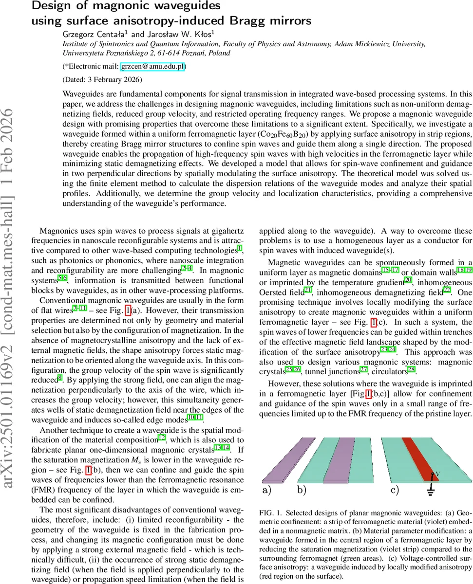
Waveguides are fundamental components for signal transmission in integrated wave-based processing systems. In this paper, we address the challenges in designing magnonic waveguides, including limitations such as non-uniform demagnetizing fields, reduced group velocity, and restricted operating frequency ranges. We propose a magnonic waveguide design with promising properties that overcome these limitations to a significant extent. Specifically, we investigate a waveguide formed within a uniform ferromagnetic layer (Co${20}$Fe${60}$B$_{20}$) by applying surface anisotropy in strip regions, thereby creating Bragg mirror structures to confine spin waves and guide them along a single direction. The proposed waveguide enables the propagation of high-frequency spin waves with high velocities in the ferromagnetic layer while minimizing static demagnetizing effects. We developed a model that allows for spin-wave confinement and guidance in two perpendicular directions by spatially modulating the surface anisotropy. The theoretical model was solved using the finite element method to calculate the dispersion relations of the waveguide modes and analyze their spatial profiles. Additionally, we determine the group velocity and localization characteristics, providing a comprehensive understanding of the waveguide’s performance.
💡 Research Summary
The paper addresses fundamental limitations of conventional magnonic waveguides—namely, reduced group velocity when the magnetization aligns with the wire axis and the emergence of edge modes caused by static demagnetizing fields when the magnetization is forced perpendicular by a strong external field. To overcome these issues, the authors propose a novel waveguide architecture that relies on spatially modulated surface anisotropy to create Bragg mirrors within a uniform ferromagnetic film, thereby confining spin waves in a defect region without altering the bulk material.
The experimental platform consists of a 6 nm thick Co₂₀Fe₆₀B₂₀ layer (low Gilbert damping α = 0.0029) sandwiched between two interfaces where a uniaxial out‑of‑plane surface anisotropy Kₛ ≈ 1.05 mJ/m² is imposed. The anisotropy is patterned into periodic strips of 50 nm width alternating with 50 nm non‑anisotropic sections, forming a 100 nm lattice constant magnonic crystal (the Bragg mirrors). A central defect strip 150 nm wide, also bearing the anisotropy, serves as the waveguide core. An in‑plane static field μ₀H₀ = 500 mT is applied perpendicular to the strips (Damon‑Eshbach geometry), ensuring that spin waves propagate along the z‑axis (parallel to the defect) with high group velocity and without edge‑mode formation.
Theoretical modeling starts from the Landau‑Lifshitz equation, linearized around the saturated state. The effective field includes the external bias, exchange, and dipolar contributions. Surface anisotropy enters solely through modified boundary conditions, which become spatially dependent via Kₛ(x). The coupled dynamic equations for the transverse magnetization components (m_y, m_z) and the magnetostatic potential ϕ are solved using COMSOL Multiphysics finite‑element simulations. Two computational tasks are performed: (i) Bloch analysis of an infinite magnonic crystal unit cell to obtain band structures and identify frequency gaps, and (ii) full‑structure eigenmode analysis of the waveguide plus two 21‑period Bragg mirrors to extract the dispersion of guided modes.
Results reveal that guided modes appear only within the band gaps of the surrounding magnonic crystals, where the Bloch wavevector k_x becomes complex. The imaginary part Im(k_x) determines the exponential decay of the mode into the mirrors, providing strong lateral confinement. Within the 20–45 GHz range, up to six guided modes are found, each associated with a distinct band gap. Low‑frequency modes (1–3) exhibit higher group velocities at small k_z (≈3–4 km s⁻¹) but experience reduced v_g as k_z increases. Higher‑frequency modes (4–6) show the opposite trend, with v_g rising again at larger k_z due to their proximity to the centre of the gap.
Localization is quantified by the inverse participation ratio (IPR). Low‑frequency modes, which must tunnel through the non‑anisotropic portions of the mirrors, display higher IPR values, indicating tighter confinement. High‑frequency modes are confined primarily by Bragg reflection; their IPR varies with k_z as the mode moves closer to or farther from the gap centre. The study also explores the trade‑off between film thickness t and effective anisotropy K_eff = −μ₀M_s² + Kₛ/t. Increasing t enhances group velocity (via stronger exchange) but weakens the anisotropy contrast, narrowing the band gaps and reducing confinement. An optimal thickness around 5–7 nm balances these effects.
The proposed surface‑anisotropy‑induced Bragg‑mirror waveguide thus achieves high‑speed, broadband spin‑wave transmission while eliminating static demagnetizing fields and edge‑mode losses. Because the anisotropy can be modulated electrically (e.g., by varying MgO thickness or voltage‑controlled interfacial anisotropy), the design offers reconfigurability absent in conventional etched wires. The authors conclude that this architecture provides a versatile platform for magnonic circuits, enabling multi‑mode operation, reduced crosstalk, and efficient signal propagation at frequencies well above the ferromagnetic resonance of the uniform film.
Comments & Academic Discussion
Loading comments...
Leave a Comment