Interpolation Techniques for Fast Channel Estimation in Ray Tracing
Ray tracing is increasingly utilized in wireless system simulations to estimate channel paths. In large-scale simulations with complex environments, ray tracing at high resolution can be computationally demanding. To reduce the computation, this paper presents a novel method for conducting ray tracing at a coarse set of reference points and interpolating the channels at other locations. The key insight is to interpolate the images of reflected points. In addition to the computational savings, the method directly captures the spherical nature of each wavefront enabling fast and accurate computation of channels using line-of-sight MIMO and other wide aperture techniques. Through empirical validation and comparison with exhaustive ray tracing, we demonstrate the efficacy and practicality of our approach in achieving high-fidelity channel predictions with reduced computational resources.
💡 Research Summary
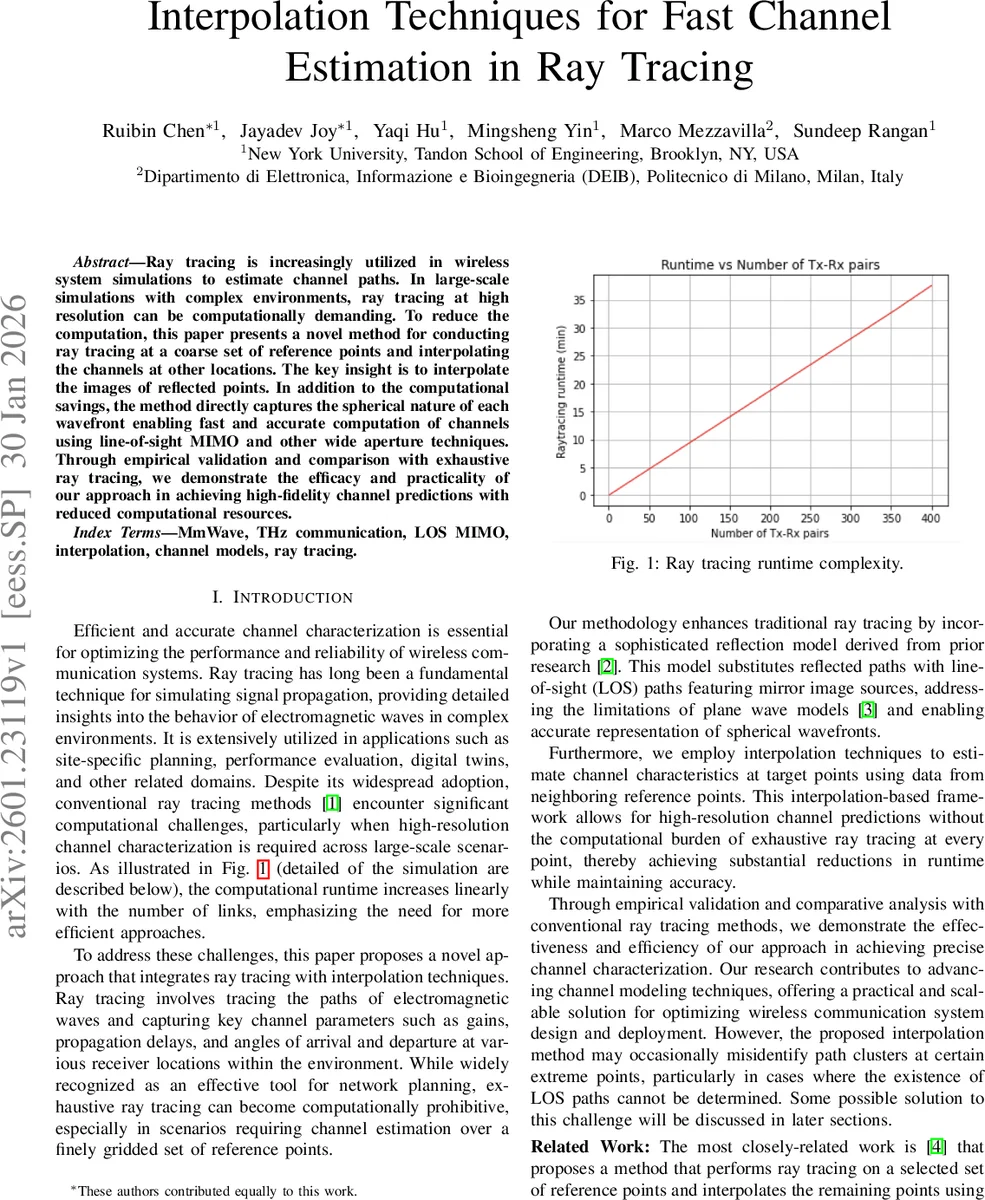
The paper addresses the prohibitive computational cost of high‑resolution ray‑tracing for large‑scale wireless system simulations. Instead of tracing every transmitter‑receiver (Tx‑Rx) pair on a dense spatial grid, the authors propose a two‑stage approach: (1) perform full ray‑tracing only at a relatively coarse set of reference receiver locations, and (2) interpolate the channel parameters at any arbitrary target location using the information gathered at the reference points.
The key technical insight is to interpolate the image of reflected points rather than the raw path parameters. By representing each specular reflection with a rotation matrix (U_\ell) and a translation vector (g_\ell), the reflected source can be mapped to a “mirror‑image” point (z_{t,\ell}=U_\ell x_t+g_\ell). The distance from any Tx antenna element to a Rx element along that reflected path is then simply the Euclidean distance between the Rx element and the image point, i.e., (|x_{r,n}-z_{t,m,\ell}|). This “Reflection Model” (RM) captures the spherical nature of wavefronts, which is essential for near‑field and wide‑aperture scenarios where plane‑wave approximations (PW A) become inaccurate.
The interpolation pipeline consists of:
- Neighbour selection – For a target point (x_r), all reference points within a tunable radius (d_{\text{th}}) are collected (set (N)).
- Path clustering – For each reference point and each of its paths, the image source is computed. Paths whose image sources are nearly identical are grouped into a cluster (k). This exploits the physical fact that paths sharing the same reflecting surface will have the same image location.
- Cluster weighting – An RBF kernel (K(\cdot)) is applied to the distances between the target and the reference points in a cluster, producing a probability metric (p_k) (Eq. 11). Clusters with low weight are discarded, ensuring that only the most relevant reflecting surfaces influence the estimate.
- Kernel regression – Within each retained cluster, the complex gains of the reference points are combined using distance‑weighted averaging (Eq. 12) to obtain the estimated gain at the target.
- Geometric parameters – Delays and angles of arrival/departure are derived directly from the geometry of the image source and the target location.
Because the image‑based distance can be inserted directly into the standard MIMO channel expression (Eq. 4), the method yields a full channel matrix (H(f)) for arbitrary Tx/Rx antenna arrays without performing ray‑tracing for each element pair. This is especially valuable for massive MIMO or THz systems where the number of antenna elements can exceed a thousand.
The authors validate the approach using NVIDIA’s Sionna ray‑tracing framework on a realistic 3‑D model of Munich’s Frauenkirche area. Simulations are run at 28 GHz with 64‑element (8 × 8) uniform planar arrays on both sides. Three propagation scenarios are considered: (a) “Most LOS” (dominant line‑of‑sight), (b) “Partial LOS”, and (c) “Total NLOS”. Reference points are placed on regular grids with spacings of 1 m, 2 m, 4 m, and 8 m.
Performance metrics include total received power error (dB), channel capacity error (%), and overall simulation runtime. Results show:
- Power error – Kernel‑based interpolation achieves sub‑1 dB average error with a 4 m grid in LOS and partial‑LOS cases, outperforming simple averaging and nearest‑neighbour methods by 3–5 dB. In pure NLOS, finer grids (≤ 2 m) are required because channel characteristics vary rapidly.
- Capacity error – For LOS‑rich environments, capacity deviation stays below 5 % even with a 4 m grid; NLOS scenarios need denser sampling to keep errors comparable.
- Computational savings – The number of full ray‑tracing runs scales with the number of reference points (Q) (O((Q))) rather than with the product of Tx/Rx antenna counts. In the reported experiments, total simulation time is reduced by 70–85 % while preserving high fidelity.
The paper also discusses limitations. In extreme NLOS zones, path clustering may fail to produce sufficient representatives, leading to degraded interpolation quality. The authors suggest future extensions such as multi‑image source modeling (including diffraction), adaptive grid refinement, and deep‑learning‑based spatial interpolation to mitigate these issues.
In summary, the work introduces a practical, physics‑driven interpolation framework that leverages image‑based reflection modeling and kernel regression to dramatically cut the computational burden of ray‑tracing while retaining accurate channel predictions. The method is particularly well‑suited for emerging 5G/6G applications involving massive MIMO, mmWave/THz frequencies, and digital‑twin simulations where high‑resolution channel data are essential but computational resources are limited.
Comments & Academic Discussion
Loading comments...
Leave a Comment