Feasibility Study of Curvature Effect in Flexible Antenna Arrays for 2-Dimensional Beam Alignment of 6G Wireless Systems
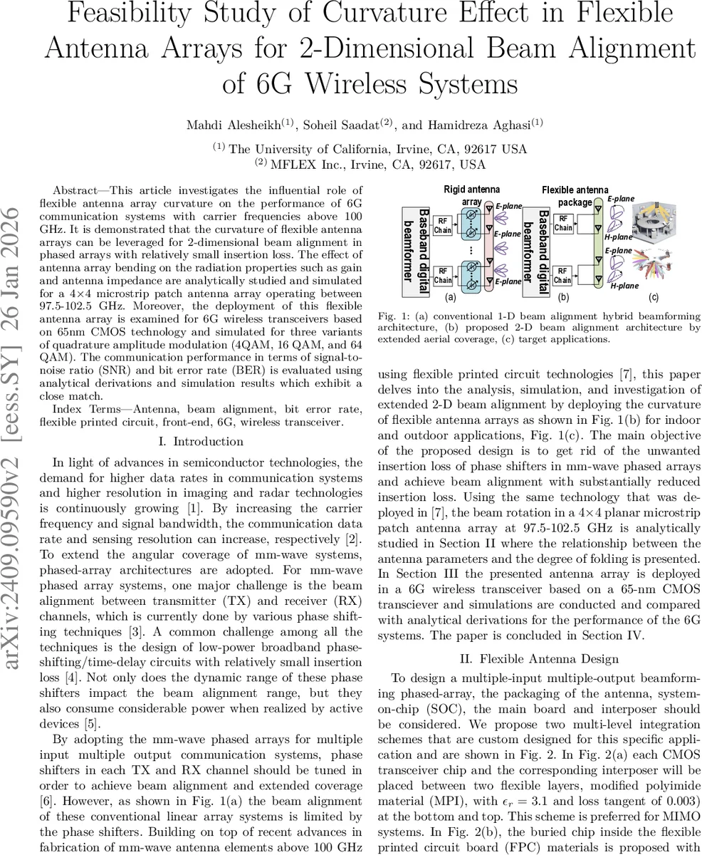
This article investigates the influential role of flexible antenna array curvature on the performance of 6G communication systems with carrier frequencies above 100 GHz. It is demonstrated that the curvature of flexible antenna arrays can be leveraged for 2-dimensional beam alignment in phased arrays with relatively small insertion loss. The effect of antenna array bending on the radiation properties such as gain and antenna impedance are analytically studied and simulated for a 4x4 microstrip patch antenna array operating between 97.5-102.5 GHz. Moreover, the deployment of this flexible antenna array in conjunction with state-of-the-art flexible board packaging techniques is examined for 6G wireless transceivers based on 65nm CMOS technology and simulated for three variants of quadrature amplitude modulation (4QAM, 16 QAM, and 64 QAM). The communication performance in terms of signal-to-noise ratio (SNR) and bit error rate (BER) is evaluated using analytical derivations and simulation results which exhibit a relatively close match.
💡 Research Summary
The paper investigates how the curvature of a flexible antenna array can be used to achieve two‑dimensional (2‑D) beam alignment for future 6G wireless systems operating above 100 GHz. A 4 × 4 microstrip patch antenna array, designed for the 97.5–102.5 GHz band, serves as the test platform. The authors first develop an analytical model that describes the electric‑field contributions of each patch element in its local spherical coordinate system, then transform these fields into a global Cartesian frame using rotation matrices that account for bending in both the x‑ and y‑directions. By approximating sin γ≈γ and cos ρ≈1 for small bending angles, closed‑form expressions for total radiated power, radiation impedance, and input impedance are derived.
Two flexible packaging schemes are proposed for integrating the antenna array with a 65‑nm CMOS transceiver. In the first scheme, each CMOS chip and its interposer are sandwiched between two layers of modified polyimide (εr = 3.1, tan δ = 0.003). In the second, the chip is buried inside the flexible printed circuit board (FPC). Experimental data from MFLEX Inc. show that a 250 µm‑thick polyimide substrate can be bent to a minimum radius of about 3 mm, and a 25 mm‑wide board can sustain bending angles up to 330°. These mechanical limits are incorporated into the electromagnetic analysis.
Simulation results from Ansys HFSS confirm the analytical predictions. When the array is bent up to 60°, the realized gain drops by less than 0.5 dBi, while the input resistance rises linearly from ~50 Ω (flat) to ~70 Ω (60° bend). Reactive impedance remains within ±5 Ω, indicating negligible matching degradation. For bends larger than 90°, destructive interference among elements severely reduces gain, confirming the theoretical expectation that excessive curvature is detrimental. Beam squint is also examined; both E‑plane and H‑plane patterns remain stable across the operating bandwidth for bends ≤60°, making the design suitable for high‑precision beam steering.
The antenna array is then embedded in a system‑level 6G transceiver model. Digital baseband generates QAM symbols (4‑QAM, 16‑QAM, 64‑QAM), which are up‑converted to RF via I‑Q mixers, amplified, and radiated through the flexible array. The receiver performs the inverse chain. Using the Friis transmission equation, the received power Pr is expressed as a function of transmitter gain, receiver gain, distance, and the complex impedances of the power amplifier and antenna. From Pr, the received‑side signal‑to‑noise ratio (SNR) is computed, and an approximate relationship between SNR and error‑vector magnitude (EVM) is used to estimate bit‑error‑rate (BER).
Results show that for modest bending (≤60°) the system can meet the BER targets of 10⁻⁶ for 4‑QAM and 16‑QAM with only a 2–3 dB SNR penalty compared to the flat case. For 64‑QAM, acceptable BER (≈10⁻²) is achieved only when the bend angle is ≤30°, because higher‑order modulation demands SNR > 20 dB, which is compromised by the slight gain loss. The analytical BER predictions match HFSS‑based Monte‑Carlo simulations within an order of magnitude; discrepancies arise from the simplifications in the field model, neglect of complex impedance contributions, and the coarse EVM approximation.
A comparative table highlights the advantage of the flexible‑antenna approach over conventional phase‑shifter (PS) or vector‑modulator (VM) beam‑steering techniques. Flexible antennas exhibit insertion losses of 2–7 dB lower than active phase‑shifters and consume negligible DC power (≤150 mW), while still providing 2‑D beam rotation without noticeable peak‑gain degradation up to 60°.
In conclusion, the study demonstrates that curvature‑induced beam steering is a viable alternative to electronic phase‑shifting for 6G millimeter‑wave arrays. By exploiting the mechanical degrees of freedom of a flexible substrate, 2‑D beam alignment can be realized with minimal insertion loss, limited beam squint, and acceptable performance for 4‑QAM and 16‑QAM modulation schemes. The work opens pathways for low‑power, high‑frequency MIMO and radar systems, though further research is needed to validate the concept with fabricated prototypes, assess thermal and mechanical reliability, and develop real‑time beam‑control algorithms for multi‑user scenarios.
Comments & Academic Discussion
Loading comments...
Leave a Comment