High-Q Millimeter-Wave Acoustic Resonators in Thin-Film Lithium Niobate Using Higher-Order Antisymmetric Modes
This letter presents miniature millimeter wave (mmWave, above 30 GHz) acoustic resonators based on a single-layer thin-film lithium niobate (LN) platform. More specifically, we present high performance third-order antisymmetric (A3) mode laterally excited bulk acoustic resonators (XBAR). Compared to prior demonstrations, the proposed platform features a compact footprint due to a smaller lateral wavelength and aperture. We showcase an A3 mode device operating at 39.8 GHz with a high extracted electromechanical coupling (k^2) of 4%, a high 3-dB series resonance quality factor (Q_s) of 97, and a high 3-dB anti-resonance quality factor (Q_p) of 342, leading to a figure of merit (FoM=k^2*Q_p) of 13.7 with a footprint of 32x44 micron^2. To demonstrate frequency scalability, the piezoelectric film thickness is varied while keeping the device layout. As a result, we present a multitude of high-performance devices covering a wide frequency range of 30-50 GHz, validating the proposed XBAR design at mmWave.
💡 Research Summary
The paper presents a novel approach to realizing high‑performance millimeter‑wave (mmWave) acoustic resonators using a single‑layer thin‑film lithium niobate (LN) platform. By exploiting the third‑order antisymmetric Lamb mode (A3) in laterally excited bulk acoustic wave resonators (XBAR), the authors achieve operation across a broad 30–50 GHz band while maintaining an exceptionally small footprint (32 × 44 µm²).
Key innovations include: (1) Selecting a thin LN film (110–160 nm) to push the acoustic wavelength into the sub‑micron regime, enabling operation at mmWave frequencies without resorting to exotic substrates such as SiC or diamond. (2) Reducing the lateral wavelength (λ_lat) to 3.15–4 µm, which dramatically shrinks the resonator aperture (≈8 λ_lat) and reduces surface‑related losses. (3) Employing ultra‑thin (50 nm) aluminum electrodes with a 50 % duty cycle, which minimizes mass loading and mechanical damping while preserving sufficient electrical drive. Finite‑element analysis (COMSOL) predicts that thinner electrodes raise the impedance ratio and improve the anti‑resonance quality factor (Q_p).
Fabrication follows a standard LN‑on‑silicon/sapphire process, with electron‑beam lithography and dry etching used to define the narrow electrode fingers and suspended acoustic cavity. Scanning electron microscopy confirms the integrity of the 50 nm Al lines and the 8 λ_lat aperture.
Electrical characterization is performed with a calibrated vector network analyzer (VNA) at –15 dBm input power. A representative device exhibits a series resonance (f_s) at 39.83 GHz with Q_s = 97 and an anti‑resonance (f_p) at 40.67 GHz with Q_p = 342. An m‑BVD (modified Butterworth‑Van Dyke) model fit yields a motional inductance of 19 nH, capacitance of 0.8 fF, resistance of 18.6 Ω, series resistance of 18.42 Ω, and series inductance of 0.1 nH. The extracted electromechanical coupling coefficient is k² ≈ 4 %.
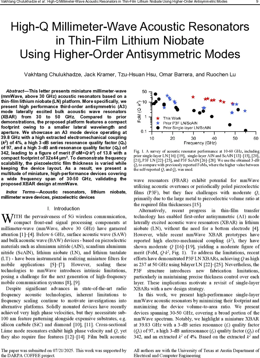
To demonstrate frequency scalability, the LN thickness is varied while keeping the layout unchanged. Devices spanning 30–50 GHz consistently show high performance: Q_p ranges from 210 to 464, Q_s from 33 to 102, and k² between 3.8 % and 4.8 %. The figure of merit (FoM = k²·Q_p) reaches values between 8 and 22.3, markedly surpassing prior single‑layer LN XBARs (FoM ≈ 3–4) and even many P3F or ScAlN devices. The f·Q product peaks at 1.4 × 10¹³, indicating excellent energy storage capability at mmWave frequencies.
A comparative table highlights that the present work achieves the best combination of normalized footprint (≈0.86 µm²·GHz⁻¹), electrode thickness (50 nm), and Q_p among reported single‑layer LN resonators. The authors attribute the remaining Q_s limitation primarily to resistive and mechanical losses in the thin Al electrodes, while Q_p is limited by intrinsic acoustic and dielectric losses that increase with frequency.
The discussion acknowledges that further improvements are possible by: (i) optimizing electrode material (e.g., low‑loss metals or alloys), (ii) fine‑tuning electrode duty cycle and thickness to balance drive strength and loss, (iii) engineering anchor geometry to suppress spurious modes, and (iv) applying post‑fabrication annealing to reduce mechanical damping. Scaling toward practical filters will involve shortening the aperture, implementing multi‑finger electrode arrays, and increasing bus‑line widths to lower routing resistance.
In conclusion, the paper demonstrates that higher‑order antisymmetric modes in thin‑film LN enable ultra‑compact, high‑Q mmWave acoustic resonators without the need for bottom electrodes or complex multilayer stacks. The demonstrated performance—high k², Q_p > 300, FoM ≈ 14, and sub‑50 µm² area—positions A3‑mode XBARs as a compelling technology for next‑generation 5G/6G front‑end filters, oscillators, and duplexers, where size, loss, and integration density are critical. Future work focusing on loss mitigation and array integration could unlock fully integrated acoustic‑RF solutions at frequencies well beyond 50 GHz.
Comments & Academic Discussion
Loading comments...
Leave a Comment