Recovery from Link Failures in Networks with Arbitrary Topology via Diversity Coding
Link failures in wide area networks are common. To recover from such failures, a number of methods such as SONET rings, protection cycles, and source rerouting have been investigated. Two important considerations in such approaches are the recovery t…
Authors: S. N. Avci, X. Hu, E. Ayanoglu
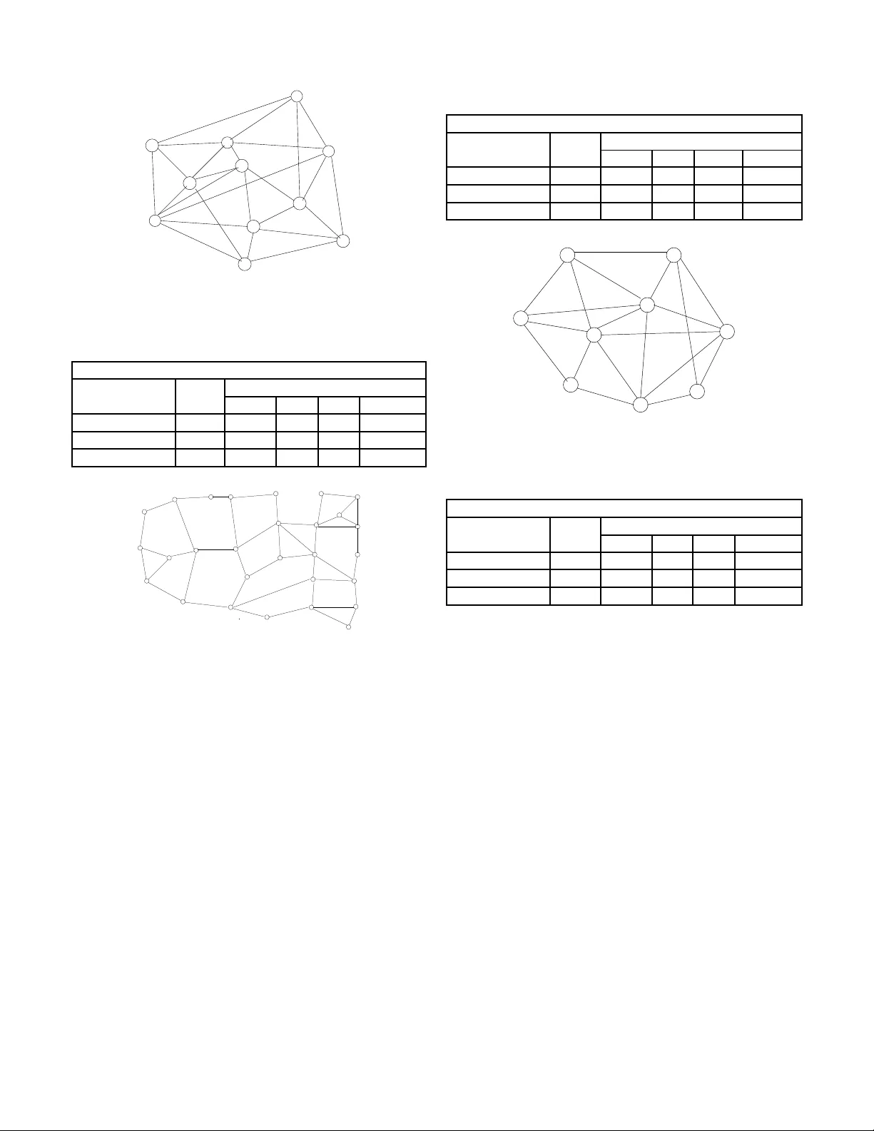
Reco v ery from Link F ail ures in Networks with Arbitra ry T opology via Di v ersity Coding Serhat Nazim A vci, Xiaodan Hu, an d Ender A yanoglu Center for Pervasi ve Communication s and Computin g Departmen t of Electrical Engineering and Com puter Science University of California, Irvin e Abstract —Link failures in wide area networks are common. T o reco ver from such failu res, a number of methods su ch as SONET rings, prote ction cycles, and sour ce rero utin g hav e been in vestigated. T wo important considerations in su ch app roaches are the r ecover y ti me and the needed spare capacity to complete the reco very . Usually , these techniques attempt to achiev e a reco very time less than 50 ms. In thi s paper we introduce an approach that pro vides link failure r ecove ry in a hitl ess manner , or without any appreciable delay . This is achieved b y means of a method called diversity coding. W e p resent an algorithm for the design of an ov erlay network to achieve reco very from sin gle link failu res i n arbitrary n etworks via d ive rsity coding. This algorithm i s designed to minimize spar e capacity for r ecov ery . W e compar e the reco very time and spare capacity p erfo rmance of this algorithm against conv entional techn iques in terms of reco very time, spare capacity , and a joint metric called Quality of Recov ery (QoR). QoR in corpora tes b oth the spare capacity percentages and wo rst case reco very times. Based on these r esults, we conclu de th at t he proposed techn ique prov ides much shorter reco very ti mes wh ile achieving similar extra capacity , or better QoR performance overall. I . I N T R O D U C T I O N Failures in co mmunicatio n networks a re comm on and c an result in substantial lo sses. For example, in th e late 1980s, the A T&T telephon e n etwork encoun tered a n umber of h ighly publicized failures [1], [ 2]. In one case, m uch of the long distance service along the E ast Coast of the U.S. was disrup ted when a co nstruction crew accide ntally severed a major fibe r optic cable in New Jersey . As a result, 3.5M call attempts were blocked [1]. On another occasio n, of the 148M calls placed du ring the nine-ho ur-long per iod of the failure, only half went through, resulting in tens of millions of d ollars w or th of collateral damag e for A T&T as well as m any of its major customers [2]. Observing that such wide- scale network failures can have a huge im pact, in Febru ary 199 2, the Federal Communication s Commission (FCC) of the U.S. issued an ord er requ esting that carriers repo rt any majo r outages affecting more than 50K customer s lasting f or more than 30 minu tes. Over a decade, the repo rts ma de av ailable to the public showed that network failures are very com mon and cause significan t service interrup tions. Accor ding to the publicly av ailable data, while most of the rep orted events im pacted up to 250 K users, some impacted million s o f users [3]. In the early 1990 s, A T&T decided to ad dress th e r estoration problem f or its long distance network with an automatic This work is partia lly supported by NSF under Grant No. 0917176 centrally controlled m esh recovery scheme, called F AST AR, based on digital cro ss-connect systems [4]. Sin ce then, this subject has seen a significant amo unt of research. In mesh- based netw or k link failure recovery , the tw o nodes at the end of the failed link can switch over to spar e cap acity . Alternatively , all the affected paths cou ld be switched over to spare cap acity in a distributed fashion. While th e former is faster , the latter will h ave smaller spare cap acity requ irement. In this paper, we will use th e term source r erouting to r efer to mesh-based link or path protection alg orithms. I n sim ulations we employ the Simplest Spare Capacity Allocatio n (SSCA) alg orithm [5]. In the mid-19 90s, spec ifications for an au tomatic pr otec- tion capab ility within the Synchron ous Op tical Networking (SONET) tran smission stan dard we re d ev elop ed. These later became the I nternatio nal T elecomm unications Union (ITU) standards G.7 07 and G.708. The basic id ea fo r protectio n is to p rovide 100% redu ndant capacity on each transmission path thr ough em ployment of ring stru ctures. SONET can accomplish fast restoration (telep hone networks have a goal of restor ation within 50 ms after a failure to keep perception of voice quality u nchang ed by human user s) at the expense of a large amou nt of spa re capacity [6], [7]. T he restoratio n times for mesh-based r erouting tech niques ar e ty pically larger than those of SONET ring s, howe ver , the extra tran sport capacity they require for restoration in th e U.S. is gen erally better than that a chiev able by SONET r ings. In late 1 990s, with other major U.S. lo ng distance c arriers moving to SONET ring s for restoration pu rposes, an industry-wid e deb ate took place as to whethe r the m esh-based restor ation or the SONET ring - based restoration is better . Th is debate still continues today . Although most research ers accep t that mesh-b ased re storation may save extra capacity , r estoration speed s achiev able with mesh-based restora tion are gener ally low and th e signaling protoco ls needed for message feedba ck are an e xtra complexity that can also complica te th e restoration process. An extension of the SONET ring s is the techniq ue kn own as p - cycles [8]. In a network, a p -cycle is a ring that goes throug h all the nodes on ce. Such a r ing will provide protection against any single link failure in the network b ecause there is always an altern ativ e path on the rin g that conn ects the n odes at the end o f the failed link , una ffected b y the failure. The recovery is car ried out by the two nodes that detec t the failure at the two ends of the failed lin k. These nod es rerou te the traffic o n this link to the co rrespon ding part of the p -cycle. Constructing p -cycles and the corresp onding spare capacity . . . - ? ? - - - - - ? ? ? ? 6 ? ? ? - - - 1 = N M j =1 d j 1 N M j =1 j 6 = i d j i d i 1 (b) (a) . . d N d 2 d 1 . . . . d 1 d 2 d N d N d 2 d 1 Detetor F ailure . . . . . . . . . . . . Fig. 1. Di versity coding where N parallel data links are protected against fail ure by one coded link. (a) E ncoder and (b) Decode r . assignment can be solved by a n umber of algorithms [8]. Some of the se algor ithms employ linear prog ramming while the re are a numb er o f simp ler design algorithms. In th is pap er , we employ the alg orithm in [8, p. 6 99], wh ich is considered to be within 5% of the optimal solution [8]. W e would like to add that in th e techniqu e of p -cycles, it is possible to subdivide the network nodes an d generate different p -cycle rings for each division separ ately [8]. Recovery fro m link failures in I P networks can take a long time [7] b ecasue I P r outing p rotocols were no t design ed to minimize network outage s. There h as been In ternet re search that shows a single link failure can cau se u sers to experience outages of sev eral minutes even when the u nderlyin g network is h ighly r edund ant with p lenty of spar e b andwidth available and with multiple ways to rou te aroun d th e failure [7]. Need- less to say , depend ing on th e ap plication, outag es o f several minutes are no t accep table, for example, for IP telep hony , e- commerce , or teleme dicine. W ithin the teleph ony transmission a nd networking co mmu- nity , hitless restor ation fro m failures is often described as an id eal [8]. Ne vertheless, with th e me thods con sidered, it could not be ach iev ed because these methods are based on message feedback and rerouting, bo th of which take time. Whereas, with our metho d, h itless or near-hitless re covery from single link failures bec omes possible g iv en delay buf fers that synchr onize the paths. Th is intro duces n on-app reciable transmission d elay . The basic techniqu e is powerful enou gh that it ca n be extended to other network failures such as multiple link or nod e failures. The co ncept of a Qu ality of Recovery (QoR) metric was introdu ced previously in ord er to find an overall metr ic that ev aluates the perform ance of a protection tec hnique and com - pares it with o thers, see e.g., [9]. Th e arguments of the QoR metric d epend on the problem and its application. In this paper, we emp loy a version o f th e QoR metric fr om [9] th at incorpo rates spare capacity percentage, re storation time, and data loss. I I . D I V E R S I T Y C O D I N G The basic id ea in di versity coding is g i ven in Fig. 1 [10], [11]. Here, digital links o f equal rate d 1 , d 2 , . . . , d N are transmitted over disjoint p aths to their d estination. For the sake of simplicity , assume tha t these link s have a c ommon source an d a com mon destinatio n, and have th e same length. A “parity link” c 1 equal to c 1 = d 1 ⊕ d 2 ⊕ · · · ⊕ d N = N M j =1 d j is transmitted over ano ther equal len gth disjoin t path. I n the case o f the failure of link d i , th e receiver can immediately form c 1 ⊕ N M j =1 j 6 = i d j = d i ⊕ N M j =1 j 6 = i ( d j ⊕ d j ) = d i since it h as d 1 , d 2 , . . . d i − 1 , d i +1 , . . . , d N av ailable and d j ⊕ d j = 0 in mod ulo-2 arith metic or logical XOR op era- tion. As a result, d i is r ecovered by employin g c 1 and d 1 , d 2 , . . . , d i − 1 , d i +1 , . . . , d N . I t is impor tant to reco gnize that this recovery is a ccomplished in a f eedfor ward fashion, without any m essage feedb ack or rero uting. W e assumed ab ove th at the so urces and the d estinations of d 1 , d 2 , . . . , d N , c 1 are the same. Div ersity codin g ca n ac- tually be extended into network top ologies where the source or the destinatio n node is not comm on. Some examples of such network top ologies includ e multi-p oint to poin t, poin t to m ulti-point and multi-po int to mu lti-point c onnectio ns. In some cases, ther e m ay be a design ated encod ing node and a design ated deco ding node , whereas in some other cases encodin g o peration can be carried out in sou rce nodes in an incrementa l fashion . Decoding operation a lso can be done only at destination nodes, i nstead of a designated intermediate n ode. Examples of the se topo logies can be fo und in [10], [1 1], [12]. Div ersity coding paper s [1 0], [11] pred ate the work that relate th e multicast information flow in networks to the min- imum cut properties of the network [13] by about a deca de. This latter work has given rise to the general area of network coding. Ho wever , in n etwork co ding, discovery o f optimal technique s to achieve multiple unica st routing in g eneral networks ha s rem ained elusiv e. In this pape r , we p rovide a systematic approa ch to the r elated pr oblem of design ing an overlay netw or k for link failure recovery in a rbitrary networks, based on [10], [11]. As stated above, the main advantage o f d iv ersity coding as a recovery technique against failur es in networks is the fact that it does n ot n eed any fee dback m essaging. Whereas, mesh- based sou rce rer outing tech niques, SONET rings, an d the technique of p -cycles do need sign aling protoc ols to co mplete reroutin g. W ith diversity coding, as soon as the failure is detected, the data can be immediately re covered. As in network coding, this req uires synchron ization of th e coded streams. W e refer th e read er to [1 0] for a description of the need for syn chroniz ation as well as how to achiev e it in div ersity coding. A. Exa mple 1 W e will now p rovide a simp le examp le r egarding the use o f div ersity coding for link failure recovery . Consider the network in Fig. 2(a). This n etwork has a similar topolo gy to the well- known butterfly network com monly used to illustrate the basic S 1 S 2 D 1 D 2 S 1 S 2 D 1 D 2 S 1 S 2 D 1 D 2 S 1 S 2 D 1 D 2 A B A B A+B A B 0 0 (a) A B A B A+B A A B A B A+B B A B A B A B (b) (c) (d) failure failure 0 A A failure A+B 0 B B A+B A+B Fig. 2. A simple example for link failure recov ery via di versity coding. concept of multicasting via network coding , first ap peared in [13]. In this examp le, the source node S 1 wishes to transmit its data A to destination node D 1 and the source node S 2 wishes to transmit its data B to destination nod e D 2 , shown by solid lines. The restoration network is sho wn via dashed lines. There is a n en coder on top wh ich for ms A ⊕ B which we show as A + B . T his data is then transmitted to the decod er node. T he decoder forms the summation of the data recei ved from the encoder and the two destination nodes. I n the case of failures, some o f these data will not b e pre sent. Howe ver , the n etwork is designed such that the de stination node will automatica lly receive the m issing data f rom the resto ration network in an automatic fashion . In this example, the central d ecoder do es not carry ou t any failure de tection. Th is task is carr ied o ut by the destination nod es D 1 and D 2 as described below . In the case of regular oper ation, the destination n odes receive their data from their data links an d recei ve “0” from the restoratio n network, as sho wn in Fig. 2(a). Assume the lin k from S 1 to D 1 carrying data A failed. In this case, both of the nodes D 1 and D 2 receive data A auto matically fr om the restoration network, as shown in Fig. 2. Node D 1 uses this data instead of wha t it sho uld h av e been receiving directly from nod e S 1 . Since node D 2 is receiving its regular da ta B directly fr om S 2 , it igno res the data transmitted by the centra l decoder . The symmetric failure c ase for the link from S 2 to D 2 is shown in Fig. 2(c). Other failure scenario s will be ignored by D 1 and D 2 since in th ose cases they receive their data directly from the respective source s S 1 and S 2 . An example of this latter mo de o f oper ation is d epicted in Fig. 2(d) . B. Exa mple 2 In this exam ple, we will show th at diversity coding can result in less spare capacity than sour ce rerou ting or p -cycles. Refer to Fig. 3(a). Th is figure shows the available to polog y o f (a) (d) (b) 1 5 4 3 2 c d 1 5 4 3 2 a+b a b a+c b+d a, p a, p 1 5 4 3 2 b, p b, p c d (c) a 1 5 4 3 2 b a or b a or b or c c d b, d Fig. 3. Spare capacit y comparison example. the ne twork. In this n etwork, each link is bid irectional. Ther e are 4 u nit rate flows in the n etwork r epresented as a , b , c, and d , whe re a and b are from no de 1 to node 4, c is fro m nod e 2 to node 4, and d is from nod e 3 to node 4. The solution for diversity coding is shown in Fig. 3(b). In this solu tion, path 1- 5-4 is a spare lin k for the pr otection of either a or b , and it car ries mo dulo-2 sum of a and b . Note that co ded signals are not limited to spar e links, as the modulo -2 sum of a and c is de li vered over the primar y p ath of a . The same applies to th e p rimary path of b . The signals are co ded in such a way th at n ode 4 can derive a, b, c, and d g iv en any four of the fiv e incoming links f orm a full-rank matrix if the remaining lin k failed. Fig. 3(c) represents th e b est solution in the c ase of source rerou ting. The up per link is used to protect any failure in transmitting a , b or c . Th e lo wer link between no des 3 and 4 is used to pro tect flow d . Different from the previous case, we nee d two unit ca pacity over the upper link between nod es 3 and 4 due to tran smission of b and d separately . The be st solutio n fo r p - cycles is given in Fig. 3(d). In th is solution, there is only o ne ring that protects ev ery signal. Due to the interme diate node 5, the p -cycles solution can not o ffer pr otection f or th e path 1-5- 4. Protection capacity p , which is unit r ate, on the cycle is reserved to c arry any failed signal a, b, c, and d since a failure af fects at most one of the se signals. This guarantee s full operation af ter a ny failure recovery with an extra cost with respect to diversity coding. Clearly , in th is example, both o f the approa ches of source rerou ting and p -cycles result in mor e spar e capa city as compare d to the app roach of diversity co ding. I I I . C O D I N G I N N E T W O R K S W I T H A R B I T R A RY T O P O L O G Y W e will now ap ply th e techn ique descr ibed in the previous section to the design of an overlay network f or recovery from link failures in ar bitrary networks. W e ap proach this problem by examining all possible comb inations of standard diversity coding [1 0], [ 11], [12]. In d oing this, o ur go al is to come up with a n etwork for which th e spare c apacity introd uced due to div ersity codin g is minimized . W e employ r edun dancy ratio [12], as the m etric that will qua ntify the efficiency of a pa rticular combination chosen . Redundancy r atio measur es the extra cap acity in troduc ed in d iv ersity coding. Due to space limitations, we refer the read er to [12] for its defin ition. A. Pr opo sed Algorithm W e will now d iscuss how we utilize the re dunda ncy ratio of e ach d iv ersity co ding co mbination in design ing an efficient div ersity cod ing scheme f or a network with ar bitrary top ology . The proposed algorithm is intend ed to searc h for all p os- sible diversity co ding combinations and select those with the smallest redun dancy ratio. T o th at end, we employ a variable called Thr eshold. The thresho ld b egins with a small value ( ThrsdLow ). Diversity codin g combin ations o f N working paths with redun dancy ratio values smaller than Thr eshold are accepted , and the n Thr eshold is increme nted u p to its maximum value ( ThrsdHgh. ) Wit hin this process, the value N is decrem ented f rom a maximu m o f N max down to 2. T he set of unprotected path s is called the De mandMatrix, and when N working paths satisfying the r edund ancy ratio are f ound, they are taken out of Demand Matrix. At th e en d, a num ber of paths m ay rem ain u ncode d. W e protect ev ery such path by a dedicated spare p ath which carries the same d ata, k nown as 1+1 APS (Autom atic Protec tion Switch). A descr iption of th e algorith m is g iv en und er the head ing Algoritm I. I n our simula tions for this paper, the nu merical values used are ThrsdLow = 1.6, Thrs dHg h = 3.0, and N max = 4 . I V . P E R F O R M A N C E M E T R I C S S C P , R T , A N D QoR There are two dominant factors that specify the performan ce of a pro tection tec hnique. These are spare c apacity percenta ge S C P and restoratio n time RT . The QoR metr ic combin es these quan tities into a single on e and presents a clearer com - parison amon g r estoration techniq ues. T he values o f S C P are calculated via simu lations over sample n etworks and traffic, which are given in the next section. W e employ the f ollowing formu la for calcu lating S C P in all simulations S C P = T o tal Capacity- Shortest W orking Capa city Shortest W o rking Capacity . Shortest W orkin g Capa city is the total c apacity wh en ther e is n o pro tection and the traffic is ro uted over shortest pa ths. The restor ation time R T is defin ed as th e lo ngest duration that the co nnection is lo st dur ing the recovery process. R T is calculated by a modified version of a for mula from [14]. For source rerouting , p -cycles, and diversity cod ing algorithms, the following f ormula s are used to calcu late the resto ration time, in respective order RT sr = F + nP + ( n + 1) · D + ( m + 1) · C + 3 · P + 3 · ( m + 1 ) · D + E P RT pc = F + ( n + 1) · D + 2 · C + P + E P RT dc = F + 2 · D + P D . As in [14], we use F : the time to detect a failure, D : node m essage p rocessing time , C : tim e to configur e a n etwork A L G O R I T H M I : C O D E A S S I G N M E N T F O R L I N K F A I L U R E R E C OV E RY V I A D I V E R S I T Y C O D I N G for Thres ho ld=ThrsdLow to ThrsdHgh do for all combin ations o f N = N max , . . . ,3,2 do if diversity ratio of comb ination ≤ Thr eshold then if f low 1 , . . . , f l ow K ∈ D M then for i = 1 to K do D M = D M − { f l ow i } end Update the total, workin g, an d space capacities end end end end for all f l ow k ∈ D M do Apply 1+1 APS protectio n D M = D M − f l ow k Update the total, working, and space capacities end switch, m : num ber of hops in the b ackup route, and n : n umber of h ops from the source nod e of the failed link to the source. P is th e pr opagatio n time fo r th e pr otection p ath, E P is the propag ation time of failure to the closest nod e and nP is the propag ation time until the error signa l reach es the source-end node. In addition, P D mean s pro pagation d elay d ifference between link-d isjoint p aths in the div ersity codin g sch eme. As in [15], we set F to 100 µ s. Similarly to [ 14], we set the variable C a number of values, i.e., 500 µ s, 1 ms, 5 ms, and 10 ms. T he particular fo rm of the QoR metric we employ is based on [9]. W e define th e contributions due to R T and S C P as Q RT = 1 1 + 400 · R T 2 , Q S C P = 1 1 + S C P 100 3 where RT is in seconds and the factor 40 0 accounts for setting Q RT = 1 / 2 for RT = 50 m s [ 9]. Similarly , norm alization with 100 is to set Q S C P = 1 / 2 wh en S C P = 10 0 . Finally , we incorp orate restor ation tim e, data lo ss, and spare capacity into the QoR metric as QoR = 2 · Q RT + Q S C P 3 where the factor 2 acc ounts for bo th r estoration time and data loss, which is pro portion al to RT [9]. V . S I M U L AT I O N R E S U LT S In this section, we will present simulation results for link recovery techn iques previously discussed, in terms of their spare capacity requ irements and th eir restoration times. The first network studied is the Eur opean COST 239 net- 1 2 3 4 5 6 7 8 9 10 11 1310 450 820 820 660 390 760 550 390 210 220 300 660 1090 340 740 730 320 565 390 600 920 400 350 320 Fig. 4. European COST 239 network. Distanc es are in km. T ABLE I C O S T 2 3 9 N E T W O R K COST 239 Network, 11 nodes, 26 span s Scheme S C P RT fo r different C values (m s) 0.5ms 1ms 5ms 10ms Div . Coding 98% 4.8 4.8 4.8 4.8 Source Rerout. 90% 39.8 41 .8 57.8 77.8 p -cycles 64% 26.1 27 .1 35.1 45.1 1 2 3 4 5 6 7 8 9 11 12 13 14 15 16 17 18 19 20 21 22 23 24 25 26 27 28 10 38 48 33 42 33 23 11 40 32 21 16 15 35 20 46 60 32 20 58 40 40 62 21 17 15 16 18 25 33 27 25 20 21 36 32 22 18 20 21 15 26 Fig. 5. U.S. long distance network. Distance s are in tens of miles. work whose topolog y is given in Figure 4 [16]. In this g raph as well as the oth ers in the sequel, the numbe rs ass ociated with the nodes represent a node index, while the numbers ass ociated with the edges correspon d to th e distance associated with the edge. The traffic deman d is ad opted from [1 6] and app lied to the simulatio n. Th is n etwork was pr eviously stu died in th e context o f lin k failure re covery [8]. W e provide S C P and R T results for the three schem es in T able I. The second network is b ased o n the U.S. lo ng-h aul optical network. Th e top ology of this n etwork is sh own in Fig ure 5. It is based o n the topolo gy given in [ 5]. In order to calculate the traffic, we emp loyed a g ravity-based mod el [1 7] and assumed the traffic betwe en two no des is directly proportion al to the produ ct of the populatio ns of the l oca tions represented by these nodes. V alu es o f S C P an d RT fo r this network are given in T able II. The third n etwork is one that fav ors div ersity cod ing over the o ther two ap proach es in terms of spare capacity . W e cam e up with th is network in or der to provid e a different example than the two previous networks. The topolog y of th is n etwork T ABLE II U . S . L O N G D I S TA N C E N E T W O R K US Long Distance Network, 28 node s, 4 5 spans Scheme S C P RT fo r different C values (m s) 0.5ms 1ms 5ms 10ms Div . Coding 106% 9.5 9.5 9.5 9.5 Source Rerout. 91% 79 .7 83.7 11 5.7 155.7 p -cycles 107% 59 .6 60.6 68.6 78.6 1 2 3 4 5 6 7 8 9 25 30 22 20 40 40 28 18 20 18 15 12 20 15 20 25 22 10 35 18 Fig. 6. Synthetic networ k. Distances are in miles. T ABLE III S Y N T H E T I C N E T W O R K Synthetic Network, 9 node s, 2 0 spans Scheme S C P RT fo r different C values (m s) 0.5ms 1ms 5m s 10ms Div . Coding 81% 0.9 0 .9 0.9 0.9 Source Rerout. 1 00% 5.7 8.2 28.2 5 3.2 p -cycles 85% 2.8 3 .8 11.8 21.8 is given in Fig. 6. The demand in th is network is set such that it is symmetric and most of it o riginates f rom and terminates at the two end node s 1 and 9 [12]. The values of S C P and RT are provided in T able II I. For this network, th e best spar e capacity results are ob tained by employing the diversity coding approa ch, similar ly to the case we showed in the example in Section II.B. Comparing the values of S C P for the three networks in T ables I-III, we observe th at the three tech niques achieve all possible S C P perfo rmance or dering s, f rom numb er one to number three. On the other hand , in terms of the RT perfo r- mance, th e proposed tech nique is always sub stantially better . As ca n be ob served, the improvement in R T p erfor mance can be close to or e ven mor e than an order o f magnitude . It is worthwhile to o bserve th at for the U.S. Long Distance network, the RT values with sou rce rerou ting or p -cycles are above th e critical thre shold of 50 ms for all values of C , the network switch r econfigu ration time. For this network , values of RT are well below the 5 0 ms threshold wh en div ersity coding is emp loyed. W e would like to note tha t RT values for diversity cod ing can b e reduce d even further . Recall that RT dc = F + 2 · D + P D . P D beco mes equal to z ero if there is one destination node and delay equalization is perform ed. In 0 1 2 3 4 5 6 7 8 9 10 0.2 0.3 0.4 0.5 0.6 0.7 0.8 0.9 1 1.1 Setup time of an OXC (ms) Quality of Recovery metric P−cycle COST−239 Source Rerouting COST−239 Diversity Coding COST−239 P−cycle US Long Dist. Source Rerouting US Long Dist. Diversity Coding US Long Dist. (a) 0 1 2 3 4 5 6 7 8 9 10 0.5 0.6 0.7 0.8 0.9 1 Setup time of an OXC in (ms) Quality of Recovery metric P−cycle Synthetic Source Rerouting Synthetic Diversity Coding Synthetic (b) Fig. 7. Quality of Recov ery metric results for all three techn iques (a) COST 239 and U.S. Long Distance network (b) Synthetic network. this case, RT will b ecome very small, ab out 300 µ s, makin g the diversity coding alternative nearly hitless. As discussed e arlier , it is p ossible to com bine RT and S C P into a single metric Q oR . Fig. 7 shows values of Q oR f or the three networks. Th e results sho w that Q oR fo r di versity coding is be tter than the oth er tech niques for all of the network s a nd for all possible values o f th e variable C . Note that while the QoR perfo rmance of sou rce re routing and p -cycles be come worse as C in creases, that o f diversity cod ing is indepen dent of C , because there is no rer outing inv olved. V I . C O N C L U S I O N In this paper, we em ployed the techniqu e of diversity coding for provid ing a sing le link failure recovery techniqu e in n etworks with arbitrary top ologies. Th is is accomplished b y finding group s of lin ks th at can be combin ed in b asic d iv ersity coding to pologies, or in other words, mappin g the arbitrar y topolog y into efficient group s of basic div ersity c oding topo lo- gies. Th is ap proach results in link failure restoration sch emes that d o n ot req uire message feedbac k or r erouting an d there- fore are extrem ely efficient in terms of th eir restoration speed as shown via realistic calculatio ns. Erasure co ding techniq ues can be employed to extend this techniqu e to recovery from more than one link an d node failures. W e would like to no te that a numb er of rec ent publicatio ns discuss a network co ding based link recovery techniqu e [18], [19], similar to div ersity codin g [ 10], [11], where advantages of th is tech nique over 1+1 APS in networks are illustrated . It should b e noted tha t, un like the sour ce rerou ting an p -cycles technique s, 1+1 APS is n ot c onsidered a n etwork restoration technique because i t is quite clear that 1+1 r estoration is highly inefficient for S C P . Th e com parison of a tech nique such as diversity codin g fo r network restoration sho uld be made against techniques such as source rerouting or p - cycles, as carried out in this pap er . R E F E R E N C E S [1] J. C. McDonald , “Public network inte grity - Avoiding a crisis in trust, ” IEEE J. Sel. Areas Commun. , vol. 12, pp. 5–12, January 1994. [2] “Ghost in the machine, ” T ime Magazine , January 29, 1990. [3] A. P . Snow and D. Straub, “Colla teral damage from anticipate d or real disasters: Ske wed perceptio ns of system and business continui ty risk, ” in Pr oc. IEEE Internatio nal Engineering Manage ment Confer ence , vol. 2, September 2005, pp. 740–744. [4] C.-W . Chao, P . M. Dollard , J. E. W eyt hman, L . T . Nguyen, and H. Eslambolchi , “F AST AR - A robust system for fast DS3 restoratio n, ” in Proc . IEEE Global Communicati ons Confer ence , December 1991, pp. 1396–1400. [5] Y . Xiong and L . G. Mason, “Restoration strategie s and spare capacity require ments in self-hea ling A TM networks, ” IE EE/ACM T rans. Netw . , vol. 7, pp. 98–110, February 1999. [6] S. V . Kartalopoulos, Understandin g SONET/SDH and ATM: Communi- cations Networks for the Next Mille nium . W ile y-IEEE Press, 1999. [7] J. -P . V asseur , M. Pickav et, and P . Demeester , Network R ecov ery: Pr otec- tion and Restorat ion of Optical, SONET -SDH, IP, and MPLS . Elsevie r , 2004. [8] W . D. Grover , Mesh-Based Survivable Networks: Options and Strate gies for Optical, MPLS, SONET, and ATM Networking . Prentice-Ha ll PTR, 2004. [9] P . Cholda, A. Jajszcyk , and K. W ajda, “ A unified Quality of Recov ery (QoR) measure, ” W ile y Inte rnational Journal of Communicati on Sys- tems , vol . 21, pp. 525–548, May 2008. [10] E. A yanoglu, C.-L. I, R. D. Gitlin, and J. E. Mazo, “Div ersity coding: Using error control for s elf-hea ling in communica tion networks, ” in Pr oc. IEEE INFOCOM ’90 , vol. 1, June 1990, pp. 95–104. [11] ——, “Di versi ty coding for transpare nt s elf-hea ling and fau lt-toleran t communicat ion netw orks, ” IEEE T rans. Commun. , vol. 41, pp. 1677– 1686, N ov ember 1993. [12] S. N. A vci, X. Hu, and E. A yanoglu, “Hitless recov ery from link failures in netw orks with arbitrar y topology , ” in Proce edings of the Informatio n Theory and Application s W orkshop , February 2011, pp. 1–6. [13] R. Ahlswede, N. Cai, S.-Y . R. Li, and R. W . Y eung, “Netwo rk infor- mation flow , ” IEEE T rans. Inf. Theory , vo l. 46, pp. 1204–1216, J uly 2000. [14] S. Ramamurthy , L. Sahasrab uddhe, and B. Mukherjee, “Survi vabl e WDM mesh networks, ” J ournal of Lightwave T echnolo gy , vol. 21, no. 4, pp. 870–883, April 2003. [15] L. Sahasrab uddhe, S. Ramamurthy , and B. Mukherjee, “Fault m anage- ment in IP-o ver-WDM netw orks: WDM protection ve rsus IP restora- tion, ” IEEE Journa l on Selected Area s in Communications , vol. 20, pp. 21–33, January 2002. [16] P . Batchel or and et al. , “Ultra high capacit y optical transmission netw orks: Final report of action COST 239, ” Facu lty Elect. Eng. Computing, Univ . Zagreb, Zagreb, Croatia , T ech. Rep., 1999. [17] Y . Zhang, M. Roughan, N. Duffield, and A. Greenber g, “Fa st accurate computat ion of large-scal e IP traf fic matrices from link loads, ” in Pro c. ACM SIGMETRICS , June 2003. [18] A. Kamal and O. Al-K ofahi, “Efficient and agile 1+N protecti on, ” IEEE T ransac tions on Communicatio ns , vol. 59, pp. 169–180, January 2011. [19] A. E. Kamal, A. Ramamoorthy , L. Long, and S. Li, “Ov erlay protecti on against link fa ilures using network coding, ” to be published, IEEE/ACM T ransac tions on Networking .
Original Paper
Loading high-quality paper...
Comments & Academic Discussion
Loading comments...
Leave a Comment