Modeling power angle spectrum and antenna pattern directions in multipath propagation environment
Most propagation models do not consider the influence of antenna patterns on the parameters and characteristics of received signals. This assumption is equivalent to the use of isotropic or omnidirectional antennas in these models. Empirical measurem…
Authors: Jan M. Kelner, Cezary Ziolkowski (Military University of Technology, Faculty of Electronics
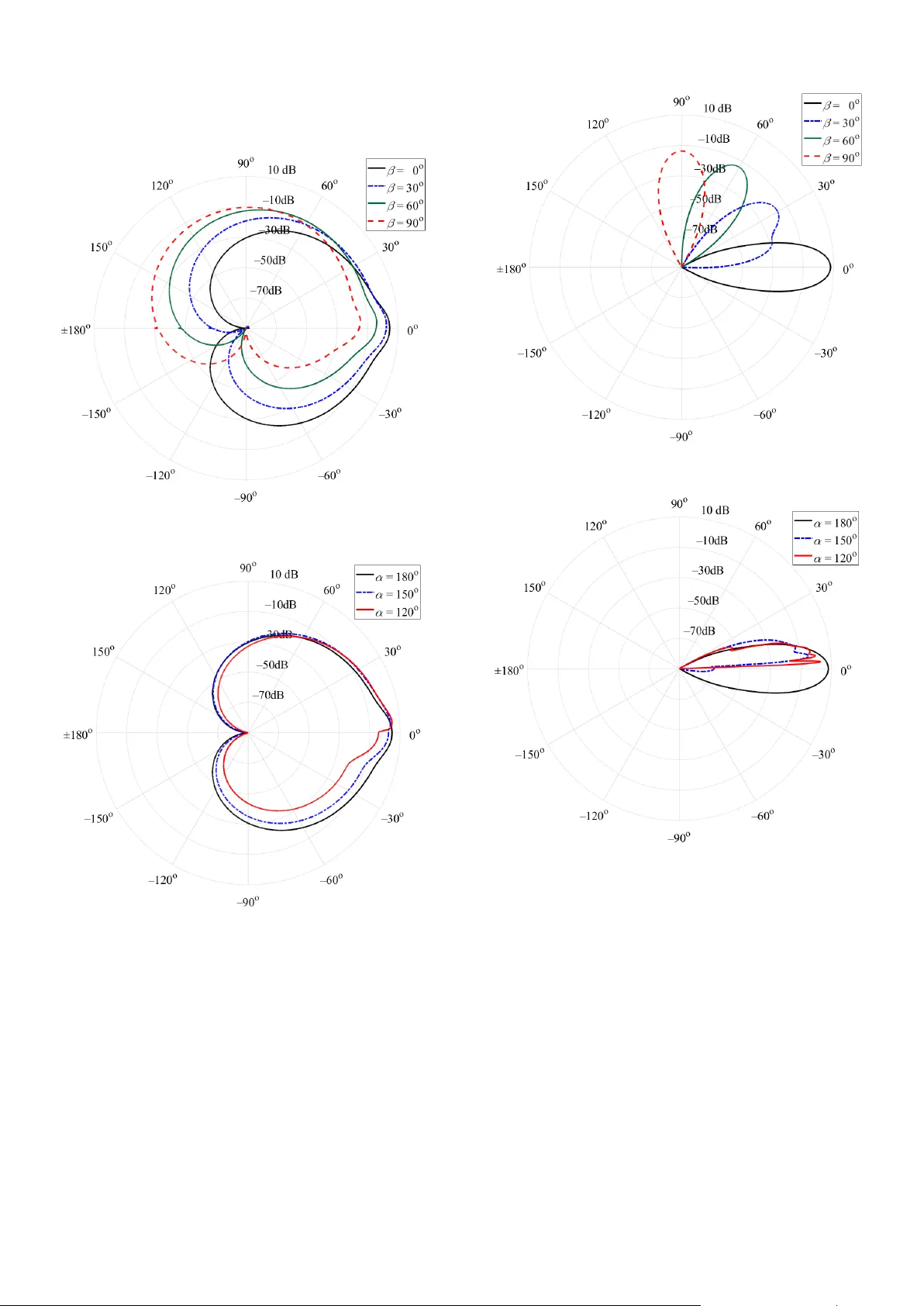
Jan M. Kelner and Cezary Ziółko wski , “ Modeling po wer angle spectrum and antenna patter n directions in multipat h propagatio n environment , ” in 2018 12 th European Conference on Antennas and Propagation (EuCAP) , London, UK, 9-13.0 4.2018. , pp. 1 – 5. Modeling Power Angle Spectrum and Antenna Pattern Directions in Multipath Propagation Environment Jan M. Kelner and Cez ary Ziółkow ski Institute of Teleco mmunications, Faculty of Electro nics, Militar y University of T echnology, Warsaw, Poland {jan.kelner, cezar y.ziolkowski}@ wat.edu.pl Abstract — Most propagation models do not co nsider the influence of antenna patterns on the parameters and characteristics of received signals. This assu mption is equivalent to the use of isotropic or o mnidirectional antenna s in these models. Empirical measurement results indicate that the radiation pattern, gai n and direction of directional antennas significantly influence o n properties of the receive d signal. This fact shows that consideration the directional antennas in propagation models is very i m portant especially in the contex t of emerging telecommunication technologies such as bea mforming or massive MIMO. The purpose of this paper is to present the modeling method of power angular s pectrum and direction of antenna patt erns in a mu ltipath propagation environment. Index Terms — multipath propagation, channel modeling, power angle sprectrum, p ower azim uth sprectru m, antenna pattern, directional antenna, multi-elliptical channel model , non-line- of -sight conditions. I. I NTRODUCTI ON A power angle spectrum (PAS) is the basic characteristi c used to estimate and model an angular dispersi on in wireless channels. PAS can be determ ined in azimu th and elevation planes. If the model includes both planes, then we are talking about 3 D models [1],[2],[3]. In 2D [4],[5],[6 ] models, only the azim uth plane is considered, and then the PAS acrony m means th e power azim uth spe ctrum . PAS is a p ractical channel characterist ic used prim arily in empirical measur ements . In the case of radio chann el modeling, theore tical characte ristic, i.e. , a probability density function (PDF) of angle of arrival (AOA), is m ore commonly used. If the ch annel m odel does n ot consi der a patt ern of a receiver (Rx) antenna, then we can assum e that an omnidirecti onal (for a 2D model) or isotropic antenna is in this model, e.g., [4], [5]. In this case, P AS and PDF of AOA shapes are identica l, while the total pow er of a received signal is propo rtionality factor betw een these characte ristics [7]. If the receiving anten na is directi onal, then we should distingu ish two types o f theoretical charact eristi cs, i.e., PDF of AOA seen at the Rx antenna input and PDF of angle of reception (AOR) seen from the Rx input, i.e., the Rx antenna output [3 ]. Therefore, P DF of AOR and P AS include the receiving antenna pattern. Two approaches are use d for PAS and PDF of AOA/AOR modeling. T he first is the geom etric channel model (GCM), which defines the area of scatterer location o f signal components and their density , e.g., [1],[4]. The second is empirical models, which are based on stan dard statistical distributi ons such as Lapl acian o r Gaussian [6]. This model type is also used to describe PAS in standard models, so- called reference models, such as the 3GPP m odel [8]. T here are also mix ed models, e.g. [2],[3], [5], where delayed scatter components of the received sig nal are d efined geometrical ly, while l ocal scatte ring com ponents ar e statis tical in n ature. The aim of the paper is to show the impact of the directi onal antenna patterns and the ir direction s on the P AS in the azim uth plane. In this case, the multi-ellipti cal channel model (MCM) is used for modelin g [2],[3 ]. The presente d results show a significant influ ence of the antenna patterns and their directi ons on the spatial d ispersi on and total p ower of the received signal. T he analysis of this issue is particula rly important for future telecom munication systems, especially in the context of beamf orming, massiv e MIMO technology , green commun ications, an d 5G sy stems. This paper is org anized as follow s. In Section II , modeling method of P AS and antenna pattern direction s using MCM is briefly described. Evaluati on of the influence of directional antennas on PAS is presented in Section III. Section IV contain s conclusi ons. II. M ODELING P AS AND A NTENNA P ATTERN In MCM, three types of the received sign al components are present. T hese a re the direct path com ponent, local scatterin g com ponents occ ur ring near the rec eiving antenna, and the delayed scattering components. To d escribe the local scatterin g, the von Mises distr ibution is used. The scatterers of delayed components are located on coaxial ellipses (2D) [5],[7],[ 9] or half-ellips oids (3D) [2],[3]. In this paper, the PAS analysis concerns only the azimuth plane, so the follow ing description refers only to ellipses, ev en in regard to lite rature descri bing the 3D model. The transmitter (Tx) and Rx are locate d in the foci of the elli pses. The MCM geometry is show n in Fig. 1. The basic input data for MCM is the power d elay profile (PDP), which represents the p ower distribution on time clusters. PDP delay s define si zes of the ellipses, w hile PDP Jan M. Kelner and Cezary Ziółko wski , “ Modeling po wer angle spectrum and antenna patter n directions in multipat h propagatio n environment , ” in 2018 12 th European Conference on Antennas and Propagation (EuCAP) , London, UK, 9-13.0 4.2018. , pp. 1 – 5. powers describe the p owers of individu al signal components [2],[3],[ 5],[7],[9 ]. Fig. 1. Ge ometry of MCM. The transm itting antenna pattern is used to generate angles of departure ( AOD) [2],[9]. Thus, the sh ape, h alf- power b eam width (HPBW ), T H P B W , and direction of the Tx antenn a pattern h as a sign ificant im pact on the PDF of AOD, and indirectly also on the P DF of AOA. In the gener al case, any shape of the antenna p attern may be used. I n this paper, we use the Gaussian to model the main lobe of the directi onal anten nas [10] 2 2 exp 4 ln 2 T TT T g HP BW Thus, AODs, T , a re generate d on th e basis of the PDF defined as [2],[9] 2 C T T T T T T f HPBW g where C T is constant n ormalizi ng the PDF of AOD that depends on T H P B W . For the delayed scattering com ponents, AOAs, R , are determ ined for the i th ellips e and each gene rated AOD [9] 2 , 2 2 1 cos sgn arc cos 1 2 cos i i T R i T i i T ee ee where c ii e d d is the eccentricity of the i th ellips e defined by i delay for 1 , 2, ..., iN , 1 N is the number of time clusters occurred in the PDP, d is the Tx-Rx distance, and c is the s peed of ligh t. For the delayed scat tering com p onents, PDFs of AOA, , d i R f , are determin ed from the obtained sets of AOAs for each ellipse. These PDFs can be determin ed in two ways, i.e., based on histogram s of AOA [ 5] or comp onent pow ers [2],[9]. Conducted studi es show that both approach es are equivalent . For the local scat tering components , AOAs are generated based on th e von Mis es distr ibution ,0 0 exp cos 2 πI R lR f where 0 I is the zero-or der modified Bessel functi on and is the distribut ion param eter describing the intensity of the local scattering . The resulting P DF of AOA seen at the receiving antenna input is describe d by [2], [9] 0 , , 0 1 0 1 1 δ 1 N i R d i R l R i RR R R PP f f f PP P P where is the Rician factor, i P is the power of the i th PDP time cluster corr esponding to the delay i for 0,1 , ..., iN , 0 N Ri i PP is the total power of the r eceived signal, and δ is the Di rac delt a function. In the case o f the isotropic or omnidirecti onal antennas, the component powers of the receive d signal are generate d on the basis of uniform distributi ons define d for each clusters. For delay ed and local scatte ring com ponents, w e have res pectively [2],[5],[ 9] 2 for 0 , 2 0 for 0 , 2 i i ij i i i ij ij i i M P p P M fp p P M 00 00 0 00 12 for 0, 2 1 0 for 0, 2 1 ji ij ji MP p P M fp p P M where ij p is the power of the j th path of the i th cluster seen at the Rx anten na input, i M is the num ber of genera ted paths in the i th cluster , 0,1 , ..., iN , and 1 , 2 , ..., i jM . In the case of the d irecti onal receiving antenna , P AS and PDF of AOD conside r also its pattern. The pattern of this antenna can be described analogously to the transmittin g antenna, i .e., Jan M. Kelner and Cezary Ziółko wski , “ Modeling po wer angle spectrum and antenna patter n directions in multipat h propagatio n environment , ” in 2018 12 th European Conference on Antennas and Propagation (EuCAP) , London, UK, 9-13.0 4.2018. , pp. 1 – 5. 2 2 ex p 4 ln 2 R RR R g HP BW where and R H P BW are the direction and width of the main lobe of the re ceiving anten na pattern , respectiv ely. The receiving antenna pattern is used to determine the power of each path seen at th e Rx antenna output 2 ,, R ij ij R R ij p p g where , R ij p is the p ower of the ij th path seen at the Rx input , correspon ds to AOA /AOR , , R ij . The obtained powers are used to determin e the estim ator of the PDF of AOD that is seen at the Rx input. For this purpose, we use the histogra m method for the path powers [3] ,, ,, 01 C R i R ij R ij R R R M N R ij R ij ij p f p L where , ,: ε R R ij R ij L , C R is constant normalizing the PDF of AOR, and ε is a neighb orhood of R . Then, we can describe the PAS seen at the input Rx as [3],[7] R R R R P P f The PAS m odeling m ethod descri bed above is used in the studies presented in this paper. III. I MPACT OF A NTENNA P ATTERNS ON PAS The impact evaluat ion o f the antenna patterns on PAS is carried out for the urban macro (UMa) scenari o and non - line- of - sight (NLOS) c ondition s , 0 . For this aim, we use PDP based o n the 3GPP tapped delay line (T DL) model, i.e., TDL- B [8, Table 7.7.2- 2] for the frequency range, 2 .4 2 .7 G H z c f , and rms delay spread, 3 6 3 ns DS [8, Table 7 .7.3- 2] . Three types of antennas are analyzed, i.e., corner reflector (CR), parabolic grid (PG), and base station antenna (BS). The HPBWs of these antennas are CR 58 H P B W , PG 10 H PB W , and BS 68 H P B W for CR, PG [11] , and BS (Kathr ein 80010 715) [12], r espectively . The Tx -Rx distances are 800 m d and 400 m d for B S and CR or PG , respectively . Figures 2, 4, and 6 show PASs for 180 , selected , and th ree analyzed types o f antennas, i.e., BS, CR, and PG, respectiv ely. While, Figs. 3, 5, and 7 present PASs for 0 , sele cted , and three antenna types, i.e., BS, CR, and PG, respective ly. Fig. 2. PA Ss fo r BS, α = 180 ° and se lected β . Fig. 3. PA Ss fo r BS, β = 0 ° and sel ected α . The obtained results show that PASs are symmetrica l for cases the antennas are directed at thems elves, i.e., for 180 and 0 . Changing the d irec tion of one antenna resu lts a deform ation of the PAS symm etr y. For B S and CR, PAS shapes are similar despite different distances . For BS and CR, HPBWs are approxim ate. T hus, Jan M. Kelner and Cezary Ziółko wski , “ Modeling po wer angle spectrum and antenna patter n directions in multipat h propagatio n environment , ” in 2018 12 th European Conference on Antennas and Propagation (EuCAP) , London, UK, 9-13.0 4.2018. , pp. 1 – 5. this param eter of the antennas have a signific ant influ ence on the PAS shape. Fo r very selective PG, PASs are also selective . Fig. 4. PA Ss for CR, α = 180 ° and sel ected β . Fig. 5. PA Ss for CR, β = 0 ° and se lected α . For 180 , changes o f cause major changes in the shape and orientation of the received P AS. For 0 , changes of cause relatively minor changes of the P AS. Thus, impact of changing the receiving antenna direction on the PAS is more sig nificantly . Fig. 6. PA Ss fo r PG, α = 180 ° and sel ected β . Fig. 7. PA Ss fo r PG, β = 0 ° and sele cted α . The obtained graphs show that the proper orientati ons o f the transmitti ng and receiving antennas signific antly impact on the PAS shape, angular dispersi on, and power of the received signal. Presente d approa ch fo r the PAS modeling is used in [ 13 ] to modify a p ath loss model for variou s orientation of directi onal antennas. T his path lo ss model only for antennas directed at each other is shown in [ 11]. IV. C ONCLUSION In this pape r, the authors presented the methodology of the PAS modeling, wh ich co nsiders the directional antennas. Jan M. Kelner and Cezary Ziółko wski , “ Modeling po wer angle spectrum and antenna patter n directions in multipat h propagatio n environment , ” in 2018 12 th European Conference on Antennas and Propagation (EuCAP) , London, UK, 9-13.0 4.2018. , pp. 1 – 5. The obtained simulation results show that the PAS sha pe closely depends on the HPBWs and directions of the antenna patterns. The proposed metho dology can be used to assess the impact o f interfe rence between antenna system s for thei r different orientati ons. This is im portant in an el ectrom agnetic compatibi lity evaluati on of radiocomm unication system s. The modeling method of the direction al antenna and P AS can also b e used to mod ify propagation models that do not consider the antenna patte rns. R EFERENCES [1] A. Ahmed, S. J. N awaz, a nd S. M. G ulfam, “ A 3 -D pro pagation model for emerging land mobile radio cell ular environme nts,” PLoS ONE , vol. 10, no. 8 , p. e0132555, A ug. 2015. [2] C. Ziółkowski and J. M. Kelner, “Antenna pattern in three - dimensional modelling of the arrival angle in sim ulation studies of wireless channel s,” IET Microw. Antennas Propag. , vol . 11, no. 6, pp. 898 – 906, May 2017. [3] C. Ziółkowski and J. M. Kelner, “Statisti cal evaluation of the azimuth and elevation angles seen at the output o f the receiving antenna,” IEEE Trans. Antennas Propag. , vol . 66, 2018. DOI : 10.1109/TA P.2018.2796719 [4] K. T. W ong, Y. I . Wu, a nd M. A bdulla, “L and mobile radiowave multipaths’ DOA -distrib ution: Assessing geometric models by the open literature’ s empirical d atasets,” IEEE Trans. Antennas Propag. , vol. 58, no. 3, pp. 946 – 958, Mar. 201 0. [5] C. Ziółkow ski and J. M. Kel ner, “Estimation of the reception angle distribution based on the power delay spectrum or profile,” Int. J. Antennas Prop ag. , vol. 2015, p. e93 6406, Dec. 201 5. [6] C. Ziółkow ski and J. M. Kelne r, “Empirical models of the azimuthal re ception angle — Part I : C omparative analysis of empirical models for different propag ation enviro nments,” Wirel. Pers. Commun. , vol. 91, no. 2, pp. 7 71 – 791, Jul. 2016. [7] C. Ziółkow ski, “Statistical model of th e angular powe r distribution for wireless mu ltipath environments,” IET Microw. Antennas Propag. , vol. 9, no. 3, pp. 281 – 289, Fe b. 2015. [8] “3GPP TR 38.901 V14.2.0 (2017 -09). Study on channel model for frequencies from 0.5 to 1 00 GHz (Release 1 4).” 3rd Generation Partnership Project (3GPP) , Technical Specification Group Radio Access Ne twork, Valbonne, Fr ance, Sep-2017. [9] C. Z iółkowski, J. M. Kelner, L . Nowosie lski, and M. W nuk, “Modeling the di stributio n of the a rrival angle b ased on t ransmitter antenna pattern,” in 2017 11t h E uropean Conference on Antennas and Propagati on (EuCAP) , Paris, Fr ance, 2017, pp. 1582 – 1586. [10] R. Vaughan and J. Bach Andersen, Channels, p ropagatio n and antennas for mobile communications . Lo ndon, UK: Institution of Electrical Engi neers, 2003. [11] J. A. Azevedo, F. E. Santos, T. A. Sousa, and J. M. A grela, “Impact of the antenna directivity on path loss for different propagation environments,” IET Microw. Ante nnas Propag. , vol. 9, no. 13, pp. 1392 – 1398, Oct. 2015. [12] “Kathrein Catalogue 2017. 690 -6000 MHz base station antennas and antenna line prod ucts,” Kathrei n, 2017. [13] J. M. Ke lner and C. Ziół kowski, “ Path loss model modi fication for various gains and directions of a ntennas,” in 2018 12th E uropean Conference on Antennas and Pr opagation (EuCAP) , L ondon, UK , 2018, pp. 1 – 4.
Original Paper
Loading high-quality paper...
Comments & Academic Discussion
Loading comments...
Leave a Comment