Localization Accuracy Improvement in Multistatic ISAC with LoS/NLoS Condition using 5G NR Signals
Integrated sensing and communication (ISAC) is anticipated to play a crucial role in sixth-generation (6G) mobile communication networks. A significant challenge in ISAC systems is the degradation of localization accuracy due to poor propagation cond…
Authors: Keivan Khosroshahi, Philippe Sehier, Sami Mekki
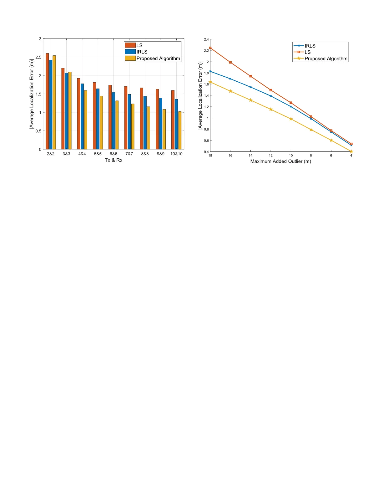
Localization Accurac y Impro v ement in Multistatic ISA C with LoS/NLoS Condition using 5G NR Signals K eiv an Khosroshahi ∗ ‡ , Philippe Sehier † , Sami Mekki † , and Michael Suppa ‡ ∗ Uni versité Paris-Saclay , CNRS, CentraleSupélec, Laboratoire des Signaux et Systèmes, Gif-sur-Yv ette, France † Nokia Standards, Massy , France ‡ Roboception, Munich, Germany kei v an.khosroshahi@centralesupelec.fr , {philippe.sehier , sami.mekki}@nokia.com, michael.suppa@roboception.de Abstract —Integrated sensing and communication (ISA C) is anticipated to play a crucial role in sixth-generation (6G) mo- bile communication networks. A significant challenge in ISA C systems is the degradation of localization accuracy due to poor propagation conditions, such as multipath effects and non-line- of-sight (NLoS) scenarios. These conditions result in outlier measurements that can sev erely impact localization perf ormance. This paper investigates the enhancement of target localization accuracy in multistatic ISA C systems under both line-of-sight (LoS) and NLoS conditions. W e leverage positioning reference signal (PRS), which is currently employed in fifth-generation (5G) new radio (NR) for user equipment (UE) positioning, as the sensing signal. W e introduce a novel algorithm to improve localization accuracy by mitigating the impact of outliers in range measurements, while also accounting for errors due to PRS range resolution. Eventually , through simulation results, we demonstrate the superiority of the proposed method ov er pre vious approaches. Indeed, we achieve up to 28% and 20% impro vements in av erage localization error over least squares (LS) and iteratively reweighted least squares (IRLS) methods, respecti vely . Additionally , we observe up to 16% and 13% en- hancements in the 90 th percentile of localization error compared to LS and IRLS, respectiv ely . Our simulation is based on 3rd Generation Partnership Pr oject (3GPP) standards, ensuring the applicability of our results across diverse en vironments, including urban and indoor areas. Index T erms —Multistatic ISA C, 6G, PRS, LS, IRLS, localiza- tion, 3GPP I . I N T R O D U C T I ON Sensing using radio signals has gained significant interest in beyond fifth-generation (B5G) and sixth-generation (6G). Integrated sensing and communication (ISA C) is anticipated to emerge as a promising technology in future wireless systems. The emergence of ISA C offers numerous sensing applications, ranging from remote healthcare and weather monitoring to target tracking, gesture recognition, autonomous vehicles, and augmented reality (AR) [1], [2]. Reference signals in wireless communication systems are known for their excellent passiv e detection performance and strong resistance to noise [3]. This has led to increased interest in dev eloping sensing signals based on reference signals. Among the various reference K. Khosroshahi’ s and M. Suppa’s w ork is supported by the H2020 MSCA 5GSmartFact project under grant ID 956670. S. Mekki’ s and P . Sehier’ s work is supported by the European Commission through the project 6G-DISA C under grant ID 101139130. signals in fifth-generation (5G) networks, the positioning reference signals (PRS) is particularly notable for sensing applications because of its abundant time-frequency resources and flexible configuration. The PRS was introduced in 3rd generation partnership project (3GPP) release 16 of the 5G specification to improve the positioning accuracy of connected user equipment (UEs) [4]. On the other hand, research on ISAC has mostly concen- trated on wa veform design and signal processing, especially in monostatic systems where the transmitter and receiver are co- located. In contrast, bistatic ISA C, where the transmitter and receiv er are not colocated, offers the advantage of eliminating the need for full-duplex capability . Multistatic ISA C, which employs multiple dispersed transmitters and receiv ers, offers advantages such as div ersity gain from independent sensing at each receiver [5]. Ho wev er , non-line-of-sight (NLoS) paths between the transmitter , receiv er , and target can lead to mea- surement errors, known as outliers. Since localization accurac y is highly sensitiv e to the outliers, it is crucial to take them into account. Therefore, one of the main challenges in localization and sensing is to efficiently mitigate the impact of outliers [6]. The research community has proposed several methods to identify and reject outliers from time of arriv al (T oA), or equiv alently , range measurements. Howe ver , the method explained in [6] suffers from a drawback as it requires a priori information re garding the status of the transmission path i.e., line-of-sight (LoS) or NLoS, and the transmission time of the signal which might not be av ailable. Authors in [7] employ a recursive weighted least squares method, which requires a single reference base station (BS) to compute the time difference of arriv al (TDoA) that leads to an inaccurate position estimation if the reference BS is identified as an outlier . Similarly , in [8], a reference BS is defined, which in- troduces the drawback that the reference itself may contain an outlier . Authors in [9] introduce a reference-free TDoA-based positioning method but does not address the issue of outlier rejection. T o overcome this issue, authors in [10], implement the iterati vely re weighted least square (IRLS) technique, which is robust to the outliers. The problem with IRLS algorithm is that it might diver ge in some cases, depending on initial values and the presence of outliers. Moreover , the previously cited works focused on the positioning of the connected de vices. The problem of outliers also exists in sensing for passi ve targets, which degrades the accuracy of location estimation. T o the best of the authors’ knowledge, passive target localization under LoS/NLoS conditions in a multistatic ISA C scenario using 5G new radio (NR) reference signal, while considering 3GPP standard constraints, has not yet been in vestigated. In this work, we focus on the localization accuracy en- hancement of an unconnected target in multistatic ISA C under both LoS and NLoS conditions. W e utilize PRS, currently employed in 5G NR for UEs positioning, as the sensing signal. W e introduce a novel algorithm that improves the localization accuracy of the target by accounting for the effects of both outliers and range estimation error caused by PRS range resolution. Simulation results demonstrate the effecti veness of our proposed method compared to least square (LS) and IRLS approaches. W e achieve significant improv ement in av erage localization error compared to LS and IRLS methods. Additionally , our results sho w considerable enhancement in 90 th percentile of the localization error compared to LS and IRLS. I I . P R S A S R E F E R E N C E S I G NA L S F O R S E N S I N G The allocation of physical resource blocks (PRBs) in 5G NR is defined in the technical specification (TS) 38.214 [11]. PRB consists of 12 consecutiv e subcarriers in the frequency domain and 14 symbols in the time domain. According to TS 38.211 [12], the generation of the PRS sequences is performed using the following equation: κ ( m ) = 1 √ 2 (1 − 2 c (2 m )) + j 1 √ 2 (1 − 2 c (2 m + 1)) (1) where c ( i ) denotes the Gold sequence of length 31. The starting value of c ( i ) for the PRS is provided in [12]. PRS allocation consists of a minimum of 24 PRBs and a maximum of 272 PRBs, illustrating the flexible transmission parameters supported in 5G NR. This flexibility allows PRS to adapt its time-frequency resource configuration to meet sensing accuracy requirements for div erse applications. As per the PRS resource mapping guidelines indicated in TS 38.211 [12], four comb structures—Comb 2, 4, 6, 12—in the frequency domain and fiv e symbol configurations—Symbol 1, 2, 4, 6, 12—in the time domain are supported. Further details on PRS configuration and resource allocation in ISAC scenarios can be found in [13]. I I I . M U LT I S T AT I C I S A C S Y S T E M M O D E L W e consider a multistatic ISA C scenario comprising S transmitters, K recei vers, and one passiv e point-like target. Figure 1 sho ws the considered setup where the UEs are configured to recei ve the downlink information from gNodeBs (gNBs) in LoS or NLoS. The locations of the gNBs and UEs are assumed to be kno wn. The location of the UEs can be determined by the positioning service provided by Fig. 1: Multistatic ISAC scenario in which the red dashed lines indicate blocked LoS links, green dashed lines indicate LoS links, and the yellow dashed lines indicate the NLoS links between gNBs, UEs, and the target. gNBs [4]. The location of the k -th UE is denoted as u k = ( x k,u , y k,u ) , u k ∈ R 2 , k ∈ { 1 , 2 , ..., K } . The point-like target is placed at x 0 = ( x 0 , y 0 ) , x 0 ∈ R 2 and s -th gNB is located at g s = ( x s,g , y s,g ) , g s ∈ R 2 , s ∈ { 1 , 2 , ..., S } . W e assume that the clocks of the gNBs could be synchronized by global positioning system (GPS) clock module [14]. The transmitted signal from s -th gNB in the continuous time domain can be expressed as [13]: Q s ( t ) = N − 1 X n =0 rect ( t − nT 0 T 0 ) M − 1 X m =0 v s ( m, n ) e j 2 πm ∆ f ( t − nT 0 ) (2) where M represents the number of subcarriers, and N is the number of symbols in the time domain in an orthogonal frequency-di vision multiplexing (OFDM) resource grid. The function rect ( t/T 0 ) denotes a rectangular pulse, ∆ f is the subcarrier spacing, and T 0 = T C P + T s is the total duration of an OFDM symbol, where T s = 1 ∆ f is the symbol duration and T C P is the cyclic prefix (CP) length. v s ( m, n ) denotes the complex symbol transmitted by s -th gNBs at the m -th subcarrier and n -th symbol, where n ∈ { 0 , 1 , ..., N − 1 } and m ∈ { 0 , 1 , ..., M − 1 } within an M × N OFDM resource grid. W e assume that UEs receive the echoes from the target and estimate the time of flights (T oFs). The reflected signals from the target, receiv ed by the k -th UE, can be expressed as [15]: Y k ( t ) = S X s =1 β s,k Q s ( t − τ s,k ) e j 2 πf d,s,k t + e ( t ) (3) where β s,k represents the attenuation factor of PRS signal sent from s -th gNB and received by k -th UE, f d,s,k is the Doppler frequency shift received by k -th UE with respect to the s -th gNB, τ s,k denotes the delay of recei ved PRS signal by k -th UE from the s -th gNB, and e ( t ) ∈ C is the complex additiv e white Gaussian noise (A WGN) with zero mean and variance of 2 σ 2 . The extracted received symbols after fast Fourier transform (FFT) for k -th UE can be written as: ˜ v k ( m, n ) = S X s =1 β s,k e j 2 πnT 0 f d,s,k e − j 2 πm ∆ f τ s,k v s ( m, n ) + p ( m, n ) (4) where p ( m, n ) ∈ C is the A WGN noise with zero mean and variance of 2 σ 2 on the n -th OFDM symbol and the m -th sub- carrier obtained from sampling and FFT over Y k ( t ) . The UE can estimate the bistatic distance ˆ r s,k , i.e., the distance from the gNB to the target and from the target to the UE, using the periodogram-based method without encountering range am- biguity [16], [17]. T o accomplish this, we first extract the re- ceiv ed PRS symbols by UE k in (4), sent from gNB s denoted, as ˜ v s,k ( m, n ) = β s,k e j 2 πnT 0 f d,s,k e − j 2 πm ∆ f τ s,k v s ( m, n ) , ∀ s ∈ { 1 , 2 , ..., S } . This extraction is feasible due to the distinct PRS offset in the time or frequency domain for each gNB. Then, we remove the transmitted PRS symbols of gNB s from the receiv ed echoes by performing point-wise division as: g s,k ( m, n ) = ( ˜ v s,k ( m,n ) v s ( m,n ) , if v s ( m, n ) = 0 0 , if v s ( m, n ) = 0 (5) Then, we perform an M -point in verse fast F ourier transform (IFFT) on the n -th column of g s,k ( m, n ) as: r n s,k ( ℓ ) = | IFFT ( g s,k ( m, n )) | = β s,k e j 2 πnT 0 f d,s,k M − 1 X m =0 e − j 2 πm ∆ f ˆ r s,k c 0 e j 2 π mℓ M + p ( m, n ) v s ( m, n ) e j 2 π mℓ M (6) where ℓ ∈ { 0 , 1 , ..., M − 1 } , | . | denotes the absolute value, and we have replaced τ s,k with ˆ r s,k c 0 where c 0 is the light speed. The maximum value in (6) is achiev ed when the argument of e − j 2 πm ∆ f ˆ r s,k c 0 e j 2 π mℓ M cancel each other out. The next step is to perform an IFFT ov er all columns of g s,k ( m, n ) and av erage the results to enhance the signal-to-noise ratio (SNR): r s,k ( ℓ ) = 1 N N − 1 X n =0 r n s,k ( ℓ ) (7) Next, we identify the index of the maximum value, denoted as ˆ ℓ s,k , in (7). Using this index, the bistatic distance of the target between UE k and gNB s can then be estimated as: ˆ r s,k = ˆ ℓ s,k c 0 ∆ f M (8) Additionally , the PRS range resolution is defined as: ∆ r = c 0 ∆ f M (9) If the target is in LoS of both gNB s and UE k , then the correct bistatic distance of the target between UE k and gNB s , denoted as r s,k , can be expressed geometrically as: r s,k = || x 0 − g s || + || x 0 − u k || (10) where || . || represents the Euclidean norm. In the next section, we discuss how to adapt existing methods for positioning con- nected devices to localize a passiv e target. W e also introduce our novel method to reduce the target localization error using ˆ r s,k , ∀ s ∈ { 1 , 2 , . . . , S } , and ∀ k ∈ { 1 , 2 , . . . , K } from (8). I V . T A R G E T ’ S L O C ATI O N E S T I M A T I O N Equation (10) is written assuming the target is in LoS of both the UE and the gNB. Howe ver , if the target is in NLoS with either the UE, the gNB, or both, the resulting error in location estimation can be significant. Additionally , the PRS range resolution defined in (9) introduces further error in localization estimation. In this section, we will first explain and adapt the LS and IRLS methods for estimating the target’ s location, taking into account the outliers and PRS range resolution. W e will then present our proposed method to further improv e localization accuracy . A. LS and IRLS Method in Sensing Considering the outlier and PRS range estimation error , we can express the bistatic distance of the target between UE k and gNB s as: ˆ r s,k = r s,k + δ s,k (11) where δ s,k represents the outlier and PRS range estimation error between gNB s and UE k , which is unkno wn. One con ventional approach to estimate x 0 is to solve the following LS optimization problem: min x 0 S X s =1 K X k =1 ( ˆ r s,k − || x 0 − g s || − || x 0 − u k || ) 2 (12) W e can solve (12) using the gradient descent method. Since the optimization problem in (12) is non-con vex, the gradient descent method con verges to a local minimum. T o improv e localization accuracy by rejecting outliers, the IRLS method can be used [10]. This alters the optimization problem to: min x 0 K X k =1 w k S X s =1 ( ˆ r s,k − || x 0 − g s || − || x 0 − u k || ) 2 (13) where w k is the weight assigned to the range estimation of UE k . W e name the objective function in (13) as f IRLS ( x 0 ) . T o solve this problem, we use the gradient descent method. Therefore, we calculate the gradient of f IRLS ( x 0 ) as follows: ∇ f IRLS ( x 0 ) = − 2 K X k =1 w k S X s =1 ( ˆ r s,k − ∥ x 0 − g s ∥ − ∥ x 0 − u k ∥ ) x 0 − g s ∥ x 0 − g s ∥ + x 0 − u k ∥ x 0 − u k ∥ (14) W e consider an initial value for x (0) 0 and set w (0) k = 1 K , ∀ k ∈ { 1 , 2 , . . . , K } . W e then iterati vely update x ( i ) 0 as follo ws: x ( i +1) 0 = x ( i ) 0 − η ∇ f IRLS ( x ( i ) 0 ) (15) where η is the step size. Algorithm 1 The algorithm for location estimation using IRLS Input: Bistatic distances ˆ r s,k , location of the gNBs g s , ∀ s ∈ { 1 , 2 , . . . , S } , location of the UEs u k , ∀ k ∈ { 1 , 2 , . . . , K } , maximum residual error e max , threshold ϵ IRLS , maximum number of iteration I max Output: Position estimation x ( i ) 0 , weights of the UEs w ( i ) i ← 1 Initial estimate of the target location x (0) 0 w (0) k ← 1 K , ∀ k ∈ { 1 , 2 , . . . , K } while i ≤ I max and ∆ IRLS > ϵ IRLS do i ← i + 1 Update x ( i ) 0 using (15) Compute residual error using (16) Update w ( i ) k with (17) Normalize w ( i ) as in (18) Compute ∆ IRLS using (19) end while retur n x ( i ) 0 , w ( i ) T o detect inaccurate measurements, we define the residual error e k for k -th UE as a measure of reliability: e ( i +1) k = 1 S S X s =1 ˆ r s,k − ( || x ( i +1) 0 − g s || + || x ( i +1) 0 − u k || ) (16) After calculating the residual errors for all UEs, the weights for the next iteration are determined using the Andrews sine function, known for its robustness in statistics and outlier rejection [18]. The weights are computed as: w ( i +1) k = e max e ( i +1) k sin ( e ( i +1) k e max ) , if e ( i +1) k ≤ e max w ( i +1) k = 0 , if e ( i +1) k > e max (17) where e max is the maximum v alue of the residual error . The weights are then normalized as: w ( i +1) k = w ( i +1) k P K k =1 w ( i +1) k (18) The con vergence check is done after each iteration as: ∆ IRLS = || x ( i ) 0 − x ( i − 1) 0 || (19) W e define ϵ IRLS as a threshold. If ∆ IRLS > ϵ IRLS , the algorithm starts repeating the process or until a maximum number of iterations I max is reached. The summary of the IRLS algorithm can be seen in Algorithm 1 where w = [ w 1 , w 2 , ..., w K ] is the vector of the UE’ s weights. B. Pr oposed Method for Localization Accuracy Impr ovement Outliers can arise in three different scenarios: 1) The target is in NLoS of the UEs. 2) The target is in NLoS of the gNBs. 3) The target is in NLoS of both the gNBs and the UEs. Since we lack priori knowledge about the occurrence of these scenarios, we account for all of them in the optimization that will be introduced later in this section. 1) The targ et is in NLoS of the UEs: In the case that the target is in NLoS with some UEs, we remov e all paths between the tar get and all the UEs to mitigate the influence of the potentially erroneous measurements that could cause outliers, as we do not kno w which UEs are in NLoS with the target. This can be done as: ˆ r s,s ′ ,k = ˆ r s ′ ,k − ˆ r s,k = || x 0 − g s || + ζ 0 ,k + γ s ′ ,k − ( || x 0 − g s ′ || + ζ 0 ,k + γ s,k ) (20) = || x 0 − g s || − || x 0 − g s ′ || + γ s ′ ,k − γ s,k ∀ s, s ′ ∈{ 1 , 2 , . . . , S } , s = s ′ , ∀ k ∈ { 1 , 2 , . . . , K } (21) where ζ 0 ,k represents the NLoS distance that the sig- nal trav els to reach UE k from the target, and γ s,k ∼ U ( − c 0 2∆ f M , c 0 2∆ f M ) , ∀ s ∈ { 1 , 2 , . . . , S } , ∀ k ∈ { 1 , 2 , . . . , K } denotes the range estimation error caused by the PRS range resolution defined in (9) between k -th UE and s -th gNB. 3GPP constraints on PRS reflect their effect on this variable. By removing the paths between the target and the UEs, we alleviate the potential error from PRS range estimation. 2) The targ et is in NLoS of the gNBs: When the target is in NLoS of some gNBs, to remove the potential error from the range estimation using PRS, we need to remov e all the paths between the target and the gNBs since we are not aware which gNBs are in NLoS with the target. This can be achieved by: ˆ r s,k,k ′ = ˆ r s,k − ˆ r s,k ′ = ζ s, 0 + || x 0 − u k || + γ s,k − ( ζ s, 0 + || x 0 − u k ′ || + γ s,k ′ ) (22) = || x 0 − u k || − || x 0 − u k ′ || + γ s,k − γ s,k ′ ∀ s ∈{ 1 , 2 , . . . , S } , ∀ k , k ′ ∈ { 1 , 2 , . . . , K } , k = k ′ (23) where ζ s, 0 denotes the NLoS distance that the signal trav els from gNB s to the target. It is important to note that while removing the paths as described in IV -B1 and IV -B2 reduces error in PRS range estimation by eliminating NLoS paths, it maintains the correctness of the range measurements when the target is in LoS with the gNBs or UEs. Considering the calculated ˆ r s,s ′ ,k and ˆ r s,s ′ ,k as (21) and (23), respectiv ely , we solve the following optimization problem: min x 0 S X s =1 K − 1 X k =1 K X k ′ = k +1 ( ˆ r s,k,k ′ − ( ∥ x 0 − u k ∥ − ∥ x 0 − u k ′ ∥ )) 2 + K X k =1 S − 1 X s =1 S X s ′ = s +1 ( ˆ r s,s ′ ,k − ( ∥ x 0 − g s ∥ − ∥ x 0 − g s ′ ∥ )) 2 (24) T o solve (24) using the gradient descent method, we denote the objectiv e function as f ( x 0 ) and driv e its gradient as: ∇ f ( x 0 ) = − 2 K X k =1 S − 1 X s =1 S X s ′ = s +1 ( ˆ r s,s ′ ,k − ( ∥ x 0 − g s ∥ − ∥ x 0 − g s ′ ∥ )) x 0 − g s ∥ x 0 − g s ∥ − x 0 − g s ′ ∥ x 0 − g s ′ ∥ − 2 S X s =1 K − 1 X k =1 K X k ′ = k +1 ( ˆ r s,k,k ′ − ( ∥ x 0 − u k ∥ − ∥ x 0 − u k ′ ∥ )) x 0 − u k ∥ x 0 − u k ∥ − x 0 − u k ′ ∥ x 0 − u k ′ ∥ (25) Using the gradient in (25), we can iteratively update x 0 as: x ( i +1) 0 = x ( i ) 0 − α ∇ f ( x ( i ) 0 ) (26) where α is the step size. The iterations proceed until || x ( i ) 0 − x ( i − 1) 0 || ≤ ϵ ∗ is satisfied. Since the optimization problem in (24) is non-con vex, this method con ver ges to a local minimum. 3) The tar get is in NLoS of both gNBs and UEs: If the tar get is in NLoS of all gNBs and UEs, the range measurements are subject to significant errors. Howe ver , applying the methods described in Sections IV -B1 and IV -B2 can improv e accuracy . Our simulations indicate that our proposed algorithm out- performs the IRLS when the target is in the LoS of at least one transmitter and recei ver . While it is unlikely that the target is in the NLoS of all transmitters and receivers in most scenarios, we propose the joint use of our method and IRLS to further enhance localization accuracy in all en vironments. T o that end, if we denote the estimated location of the target using IRLS algorithm as x IRLS 0 and the introduced algorithm as x ∗ 0 , the ultimate estimated location can be defined as follows: ˆ x 0 = ( ν IRLS x IRLS 0 + ν ∗ x ∗ 0 , if IRLS con verges x ∗ 0 , if IRLS div erges (27) where ν IRLS and ν ∗ are positiv e weights assigned to the location estimates of the IRLS and the proposed method, respectiv ely , where ν IRLS + ν ∗ = 1 . ν IRLS and ν ∗ can be chosen based on the considered en vironment. In dense environments, such as factories, where the target is most likely in NLoS of all transmitters and receivers, we increase the weight of x IRLS 0 by raising ν IRLS . Con versely , in the areas where the target is likely in LoS of at least one transmitter and recei ver such as rural en vironments, we assign more weight to x ∗ 0 by increasing ν ∗ . This adaptive strategy allows us to mitigate the limitations of each method, as different scenarios can occur unpredictably . Additionally , the method in (27) is robust against diver gence, unlike IRLS. In the next section, we compare the simulation results of LS, IRLS, and the proposed method in (27). V . S I M U L A T I O N R E S U LT S T o validate the introduced approach, we use Matlab 5G toolboxes to make this work 3GPP standards compliant. W e simulate a scenario where multiple gNBs, UEs and a target are randomly distrib uted in 400 m × 400 m, 200 m × 200 m and 150 m × 150 m area, respectively , and ν IRLS = ν ∗ = 1 2 . The carrier frequency is set to 28 GHz, subcarrier spacing is 120 kHz and PRB of PRS is equal to 66 which corresponds to 100 MHz in frequency range 2 (FR2) transmission bandwidth configurations defined in TS 38.104 [19]. The PRS comb size is set to 12 , allowing up to 12 gNBs to participate in sensing. Giv en such configuration, ∆ r is 3 . 15 m based on (9), which means that besides outliers, we have taken the 3 . 15 m error caused by PRS range resolution into account as well in the simulations. W e also set e max to 7 , α to 0 . 001 , η to 0 . 01 , and ϵ IRLS and ϵ ∗ to 0 . 01 . In the simulations, the number of outliers is uniformly distributed between zero and S + K . In Figure Fig. 2: CDFs of different methods. T ABLE I: Localization error comparison. A verage localization 90th percentile (m) error (m) LS 1.28 2.08 IRLS 1.19 2.01 Proposed method 0.96 1.74 2, we present the cumulative distribution function (CDF) of different methods while the number of gNBs and UEs is 6 . T o simulate the effect of outliers, we randomly add outliers in the range estimations, with values up to 10 m using uniform distribution. The results demonstrate that the proposed method outperforms the other methods. T able I provides a numerical analysis of different methods with the mentioned configura- tion. The introduced algorithm in this work shows almost 20% improv ement in av erage localization error compared to the IRLS and 25% improv ement compared to the LS. Additionally , we achiev e 13% and 16% improv ement in 90 th percentile of localization error compared to IRLS and LS, respectiv ely . Figure 3 illustrates the impact of the number of gNBs and UEs on av erage localization error while the outliers are randomly added up to 14 m to the dif ferent paths between different gNBs and UEs. As sho wn in Figure 3, when the number of gNBs and UEs is sufficient (e.g., 4 gNBs and 4 UEs in this simulation), the proposed method outperforms both IRLS and LS. Additionally , the results indicate that increasing the number of gNBs and UEs leads to a notable improvement in localization accuracy using our proposed method. In contrast, the gains from adding more gNBs and UEs become marginal when using the LS method or IRLS beyond a certain point. Figure 4 provides useful insight on the sensitivity of the different algorithms based on the maximum added outlier . W e randomly added outliers from 4 m to 18 m with uniform distribution to the random paths between the gNBs and the target and between target and UEs, with the number of gNBs and UEs fix ed at 6 . The results re veal that the proposed method Fig. 3: Comparison of the localization error . significantly enhances target localization accuracy . Depending on the lev el of added outliers, the proposed method achieves up to 28% accuracy enhancement compared to LS and up to 20% improv ement compared to IRLS. V I . C O N C L U S I O N In this work, we introduced a nov el method to improv e the accuracy of target localization in multistatic ISA C scenario using PRS when the target is in LoS or NLoS of the UEs and gNBs. W e used PRS as the sensing signal, which is currently used in 5G NR UE positioning, and we validated our methods using the MA TLAB 5G toolbox, ensuring compliance with 3GPP standards. T o the best of our knowledge, this study presents the first proof of concept for using PRS to localize a target under LoS/NLoS conditions, taking into account both 3GPP standard constraints and the range estimation error caused by PRS range resolution. The results show up to 28% and 20% improvement in average localization error compared to the LS and IRLS, respectiv ely . Additionally , the results show that we can reach up to 16% enhancement in 90 th percentile compared to LS and 13% compared to IRLS. Our findings demonstrated that with a sufficient number of UEs and gNBs, the proposed method is robust to outliers as it outperforms IRLS and LS in various scenarios with different outlier conditions. R E F E R E N C E S [1] A. Behravan et al. , “Positioning and sensing in 6G: Gaps, challenges, and opportunities, ” IEEE V ehicular T echnology Magazine , vol. 18, no. 1, pp. 40–48, 2022. [2] E. C. Strinati et al. , “T owards distributed and intelligent integrated sensing and communications for 6G networks, ” IEEE W ireless Com- munications (arXiv preprint arXiv:2402.11630) , 2025. [3] Z. W ei et al. , “5G PRS-based sensing: A sensing reference signal ap- proach for joint sensing and communication system, ” IEEE T ransactions on V ehicular T echnology , vol. 72, no. 3, pp. 3250–3263, 2022. [4] 3GPP , “Study on NR positioning support, ” 3rd Generation Partnership Project (3GPP), T echnical Specification (TS) 38.855, 2019, v16.0.0. Fig. 4: Outlier sensitivity of each method. [5] Z. Behdad, Ö. T . Demir, K. W . Sung, E. Björnson, and C. Cavdar , “Multi-static target detection and power allocation for integrated sensing and communication in cell-free massive mimo, ” IEEE T ransactions on W ireless Communications , vol. 23, no. 9, pp. 11 580–11 596, 2024. [6] W . W ang et al. , “Robust weighted least squares method for TO A-based localization under mixed LOS/NLOS conditions, ” IEEE Communica- tions Letters , vol. 21, no. 10, pp. 2226–2229, 2017. [7] K. Lee et al. , “Iterati ve regression based hybrid localization for wireless sensor networks, ” Sensors , vol. 21, no. 1, p. 257, 2021. [8] M. Rosi ´ c, M. Simie, and P . Luki ´ c, “TDOA approach for target localiza- tion based on improved genetic algorithm, ” in 24th T elecommunications F orum (TELFOR) , 2016, pp. 1–4. [9] A. Amar and G. Leus, “ A reference-free time difference of arriv al source localization using a passiv e sensor array , ” in IEEE Sensor Array and Multichannel Signal Processing W orkshop , 2010, pp. 157–160. [10] M. Henninger et al. , “Probabilistic 5G indoor positioning proof of con- cept with outlier rejection, ” in Joint Eur opean Conference on Networks and Communications & 6G Summit (EuCNC/6G Summit) , 2022, pp. 249–254. [11] 3GPP , “NR; physical layer procedures for data, ” 3rd Generation Partner- ship Project (3GPP), T echnical Specification (TS) 38.214, 2024, v18.2.0. [12] ——, “NR; physical channels and modulation, ” 3rd Generation Partner - ship Project (3GPP), T echnical Specification (TS) 38.211, 2024, v18.2.0. [13] K. Khosroshahi, P . Sehier, and S. Mekki, “Doppler ambiguity elimina- tion using 5G signals in integrated sensing and communication, ” in IEEE 100th V ehicular T echnology Confer ence (VTC2024-F all) , 2024, pp. 1–6. [14] P . Vyskocil and J. Sebesta, “Relative timing characteristics of GPS tim- ing modules for time synchronization application, ” in IEEE International workshop on satellite and space communications , 2009, pp. 230–234. [15] K. M. Braun, “OFDM radar algorithms in mobile communication net- works, ” Ph.D. dissertation, Karlsruhe, Karlsruher Institut für T echnologie (KIT), 2014. [16] K. Khosroshahi, P . Sehier , and S. Mekki, “Leveraging PRS and PDSCH for integrated sensing and communication systems, ” IEEE Global Communications Conference (GLOBECOM) , 2024. [Online]. A vailable: https://arxiv .org/abs/2408.00667. [17] ——, “Superposition of PRS and PDSCH for ISAC system: Spectral efficienc y enhancement and range ambiguity elimination, ” IEEE Consumer Communications and Networking Confer ence (CCNC) , 2025. [Online]. A vailable: https://arxiv .org/abs/2409.20420. [18] D. F . Andrews and F . R. Hampel, Robust estimates of location . Prince- ton University Press, 2015. [19] 3GPP , “NR; base station (BS) radio transmission and reception, ” 3rd Generation Partnership Project (3GPP), T echnical Specification (TS) 38.104, 2024, v18.6.0.
Original Paper
Loading high-quality paper...
Comments & Academic Discussion
Loading comments...
Leave a Comment