Contingency Identification of Cascading Failures in Power Transmission Networks
Due to the evolving nature of power systems and the complicated coupling relationship of power devices, it has been a great challenge to identify the contingencies that could trigger cascading blackouts of power systems. This paper provides an effect…
Authors: Chao Zhai, Hehong Zhang, Gaoxi Xiao
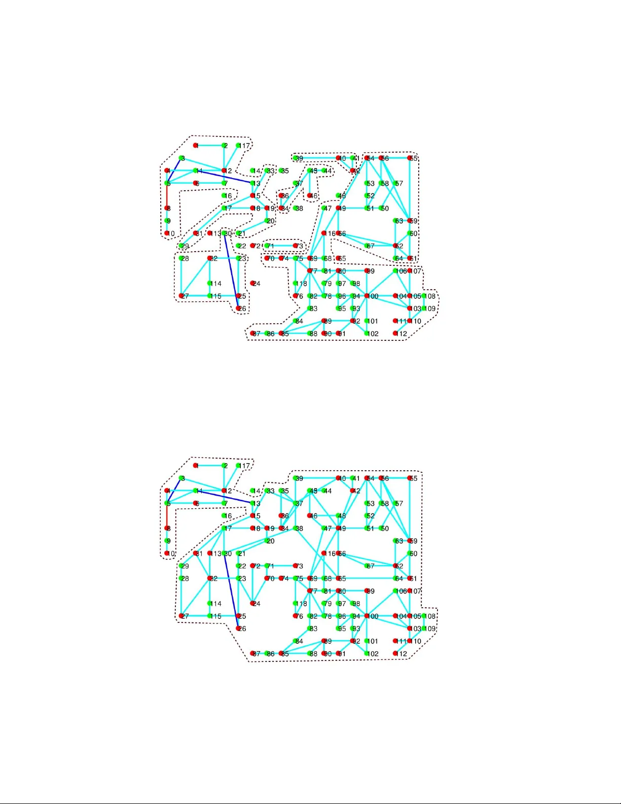
Contingenc y Identification of Cascading F ailures in Po wer T ransmission Networks Chao Zhai, Hehong Zhang, Gaoxi Xiao and Tso-Chien Pan * December 20, 2024 Abstract Due to the ev olving nature of po wer systems and the complicated coupling relationship of po wer devices, it has been a great challenge to identify the contingencies that could trigger cascading black- outs of power systems. This paper provides an ef fective approach to identifying the initial contin- gency in power transmission networks, which are equipped with flexible alternating current trans- mission system (F A CTS) devices, high-voltage direct current (HVDC) links and protecti ve relays. Essentially , the problem of contingency identification is formulated in the framew ork of nonlinear programming, which can be solved by the Jacobian-Free Newton-Krylov (JFNK) method to cir- cumvent Jacobian matrix and reduce the computational cost. Notably , the proposed identification approach is also applied to complicated cascading failure models of power systems. Finally , numer- ical simulations are carried out to validate the proposed identification approach on IEEE 118 Bus Systems. The proposed approach succeeds in reconciling the rigorous optimization formulation with the practical modeling of cascading blackouts. K eyw ords: Cascading failures, contingency identification, power transmission networks, nonlinear programming 1 Intr oduction The past decades hav e witnessed several large blackouts in the world such as India Blackout (2012), US-Canada Blackout (2003), Italy Blackout (2003) and Southern Brazil Blackout (1999) to name just * Chao Zhai, Hehong Zhang, Gaoxi Xiao and Tso-Chien Pan are with Institute of Catastrophe Risk Management, Nanyang T echnological Univ ersity , 50 Nanyang A venue, Singapore 639798. They are also with Future Resilient Systems, Singapore- ETH Centre, 1 Create W ay , CREA TE T ower , Singapore 138602. Chao Zhai, Hehong Zhang and Gaoxi Xiao are also with School of Electrical and Electronic Engineering, Nanyang T echnological University . Corresponding author: Gaoxi Xiao. Email: egxxiao@ntu.edu.sg 1 a fe w , which ha ve left millions of residents without power supply and caused huge financial losses [1]. In such catastrophe ev ents, the initial contingencies ( e . g . extreme weather , terrorist attack and operator error) play a crucial role in triggering the cascading outage of po wer systems. It is reported that the mal- operation of a protection relay is the ke y “trigger” of the final line outage sequence in most blackouts [2]. For instance, con ventional relays may lead to unselecti ve tripping under high load conditions, which could initiate the chain reaction of branch outages under certain conditions (e.g., a wrong relay operation of Sammis-Star line in the 2003 US-Canada Blackout [2]). The reliability and resilience of power grids are closely related to the proacti v e elimination of disruptiv e initial contingencies. Thus, it is vital to identify the initial contingency that causes the most sev ere blackouts and work out remedial schemes against cascading blackouts in adv ance. In practice, electrical power devices such as F A CTS de vices, HVDC links and protecti ve relays serve as the major protectiv e barrier against cascading blackouts. T o be specific, F A CTS de vices significantly contribute to the stability improvement of power systems, while HVDC links behave like a “fire wall” to prev ent the propagation of cascading outages. Actually , the F ACTS devices hav e been widely in- stalled in po wer transmission networks to improve the capability of power transmission, controllability of power flow , damping of power oscillation and post-contingency stability . As a series F A CTS de- vice, the thyristor -controlled series capacitor (TCSC) allo ws fast and continuous adjustments of branch impedance in order to control the po wer flow and improve the transient stability [3]. In addition, the HVDC links assist in prev enting cascades propagation and restoring the po wer flo w after faults. For example, Qu ´ ebec power system in Canada survi ved the cascades in the 2003 US-Canada Blackout due to its DC interconnection to the US power systems [2]. As the most common protection de vice, protectiv e relays of po wer system react passively to the system oscillation and promptly remov e the overloading elements without affecting the normal operation of the rest of the system. Meanwhile it allo ws for time delay of abnormal oscillations to neglect the trivial disturbances and av oid the overreaction to the tran- sient state changes [4]. It is necessary to tak e into account the protection mechanism of the above power de vices for the practical cascading dynamics of po wer systems. Owing to simplicity , efficienc y and scalability in the simulation, the DC po wer flow model has been widely adopted to in vestigate cascading failures of po wer systems [5, 6]. It is demonstrated that the DC po wer flow model is able to assess the vulnerability of power grids and re veal informativ e details of cascading failure process, including the size, contributing factors and the duration of cascading failures [6]. Additionally , the model predictive control can be applied to mitigate the cascading ef fect of severe line-ov erload disturbances in power systems [5]. Actually , the DC po wer flo w model is usually regarded as a good substitute for the A C based model in high voltage power transmission networks [7, 8]. As 2 a result, the DC po wer flo w equation is employed in this work to compute the transmission po wer on branches of po wer transmission networks. So far , cascading blackouts of power systems ha ve been inv estigated through two distinct routes. Specifically , some researchers aim at the strict mathematical formulation for the exploration of vulnerable elements in po wer systems regardless of the transient response and protection mechanisms [5, 9], while others focus on the practical physical process and accurate modeling of cascading black outs [4, 6]. While the former may fail to reflect the real physical characteristic of cascading failures, the latter is in lack of a rigorous theoretical frame work. This work attempts to fill the gap between the practical modeling of cascading blackouts and the strict mathematical formulation by properly decoupling the optimization problem and cascading dynamics of power grids. The main contributions of this paper are listed as follo ws 1. Propose the cascading dynamics of power transmission networks equipped with F A CTS devices, HVDC links and protecti ve relays. 2. F ormulate the problem of contingency identification with nonlinear programming and solve it via the ef ficient numerical method. 3. V alidate the proposed approach on the large-scale power transmission networks using different protection schemes. The outline of this paper is organized as follows. Section 2 presents the cascading dynamics of po wer transmission networks. Section 3 provides the optimization formulation and theoretical results on the contingenc y identification, follo wed by numerical methods in Section 4. Next, the identification approach is v alidated in Section 5. Finally , we conclude the paper and discuss future work in Section 6. 2 Cascading Dynamics This section aims to characterize the cascading e volution of po wer transmission networks subject to the initial contingency and system stresses. Figure 1 presents the cascading process of po wer systems after the initial contingency is added on the system. First of all, the F A CTS de vices take ef fect to adjust the branch admittance and balance the power flow for relieving the stress of power networks. If the stress is not eliminated, protectiv e relays will be acti v ated to serve the overloading branches on the condition that the timer of circuit breakers runs out of the preset time. Under certain circumstances, the outage of ov erloading branches may result in sev erer stress of power networks and ends up with having cascading 3 Figure 1: Cascading failure process of power transmission netw orks. blackouts of po wer systems. T o describe the cascading process, we introduce the concept of cascading step. Essentially , a cascading step is defined as one topological change ( e . g . , one branch outage) of po wer networks due to contingencies, human interferences or the branch ov erloads. The models of the DC po wer flo w , F A CTS devices, HVDC links and protecti ve relays are presented in sequence. 2.1 DC Power Flow Model For high-v oltage power transmission netw orks, the DC po wer flow equation is well qualified to describe the quantitati ve relationship of injected b us power , branch susceptance and voltage angle as follo ws P b = A T d iag ( B ) A θ (1) where A denotes the branch-bus incidence matrix [10] and θ refers to the vector of voltage angles. P b represents the vector of injected po wer on each bus. Additionally , B = ( B 1 , B 2 , ..., B n ) is the susceptance vector for branches, and each element B i is gi ven by B i = − 1 X C , i + X i , i ∈ I n = { 1 , 2 , ..., n } where X C , i denotes the reactance of TCSC equipped on Branch i , and X i represents the original reactance of Branch i . The DC power flo w equation (1) can be solved as θ = A T d iag ( B ) A − 1 ∗ P b 4 Figure 2: Control diagram of TCSC on branches. where the operator − 1 ∗ denotes the operation of matrix in verse, which is defined in [11]. Then the vector of transmission po wer on each branch can be computed by P e = d iag ( B ) A A T d iag ( B ) A − 1 ∗ P b (2) Notably , the generator bus connected to the largest generating station is selected as the slack b us, and thus the po wer v ariation of slack bus accounts for a small percentage of its generating capacity . 2.2 F A CTS Devices F A CTS devices can greatly enhance the stability and transmission capability of power systems. As an ef fecti ve F ACTS device, TCSC has been widely installed to control the branch impedance and reliev e system stresses. The dynamics of TCSC is described by a first order dynamical model [12] T C , i d X C , i d t = − X C , i + X re f , i + u i , X min , i ≤ X C , i ≤ X max , i i ∈ I n (3) where X re f , i refers to its reference reactance of Branch i for the steady power flow . X min , i and X max , i are the lower and upper bounds of the branch reactance X C , i respecti vely and u i represents the supplemen- tary control input, which is designed to stabilize the disturbed po wer system [13]. For simplicity , PID controller is adopted to regulate the po wer flow on each branch u i ( t ) = K P · e i ( t ) + K I · Z t 0 e i ( τ ) d τ + K D · d e i ( t ) d t (4) where K P , K I and K D are tunable coef ficients, and the error e i ( t ) is giv en by e i ( t ) = P re f e , i − | P e , i ( t ) | , | P e , i ( t ) | ≥ P re f e , i ; 0 , otherwise. Here, P re f e , i and P e , i ( t ) denote the reference transmission po wer and the actual transmission power of Branch i , respecti vely . Note that TCSC fails to function when the transmission line is se vered. Figure 2 presents the diagram about the operation of TCSC via PID controller to reach the reference transmission 5 Figure 3: Schematic diagram of monopolar HVDC link and its equiv alent circuit. po wer . First of all, we compute the error e i ( t ) between the actual po wer P e , i ( t ) and the reference po wer P re f e , i . Next, the PID controller produces the control input u i ( t ) based on e i ( t ) , which regulates the reac- tance of TCSC on Branch i . Finally , the actual po wer P e , i ( t ) will con ver ge to the reference power P re f e , i as time goes. 2.3 HVDC Links In practice, the HVDC link works as a protectiv e barrier to prev ent the propagation of cascading outages, and it is normally composed of a transformer , a rectifier , a DC line and an in verter (see Fig. 3). Actually , the rectifier terminal can be regarded as a bus with real power consumption P r , and the in verter terminal can be treated as a b us with real po wer generation P i . The direct current from the rectifier to the in verter is computed as follo ws [14] I d = 3 √ 3 ( cos α − cos γ ) π ( R cr + R L − R ci ) , where α ∈ [ π / 30 , π / 2 ] denotes the ignition delay angle of the rectifier, and γ ∈ [ π / 12 , π / 9 ] represents the extinction advance angle of the inv erter . R cr and R ci refer to the equiv alent communicating resistances for the rectifier and in verter , respecti vely . Additionally , R L denotes the resistance of the DC transmission line. Thus the power consumption at the rectifier terminal is P r = 3 √ 3 π I d cos α − R cr I 2 d , (5) and at the in verter terminal is P i = 3 √ 3 π I d cos γ − R ci I 2 d = P r − R L I 2 d . (6) Notably , P r and P i keep unchanged when α and γ are fixed. 6 2.4 Protecti ve Relay The protective relays are indispensable components in power systems protection and control. When the transmission power exceeds the giv en threshold of the branch, the timer of circuit breaker starts to count down from the preset time [4]. Once the timer runs out of the preset time, the transmission line is se vered by circuit breakers and its branch admittance becomes zero. Specifically , the vector of branch susceptance at the k -th cascading step is giv en by B k = G ( P k − 1 e , σ ) ◦ F ( B k − 1 ) (7) where the operator ◦ denotes the Hadamard product, and σ = ( σ 1 , σ 2 , ..., σ n ) represents the threshold vector of transmission po wer on each branch. F ( B k − 1 ) provides the vector of branch susceptance at the ( k − 1 ) -th cascading step, and it updates constantly due to the dynamics of F A CTS de vices. Additionally , the vector function G ( P k − 1 e , σ ) is used to characterize the branch outage as follows G ( P k − 1 e , σ ) = g ( P k − 1 e , 1 , σ 1 ) g ( P k − 1 e , 2 , σ 2 ) . g ( P k − 1 e , n , σ n ) ∈ R n And each element of G ( P k − 1 e , σ ) is a step function as follows g ( P k − 1 e , i , σ i ) = 0 , | P k − 1 e , i | > σ i and t c > T ; 1 , otherwise. where T is the preset time of the timer in protecti ve relays, and t c denotes the counting time of the timer . Intuitively , the branch outage occurs when its transmission power is larger than the threshold and meanwhile its timer runs out. The e v olution time of cascading failure is introduced to allo w for the time f actor of cascading black- outs. Essentially , the time interval between two consecutiv e cascading steps basically depends on the preset time of the timer in protecti ve relays [4]. Thus, the e v olution time of cascading failure is roughly estimated by t = k T at the k -th cascading step. 3 Optimization F ormulation Since cascading blackouts result in the se vere damage of po wer transmission, we focus on the po wer transmission at the end of cascading outages and thus design the cost function as follo ws J ( δ , B m ) = 1 2 k P m e ( δ ) k 2 (8) 7 where P m e ( δ ) denotes the vector of transmission power on each branch at the m -th cascading step, and δ ∈ [ δ , ¯ δ ] characterizes the admittance change of the selected branch caused by the initial contingency . Specifically , the vector of transmission power P m e ( δ ) after the contingency can be computed by P m e ( δ ) = d iag ( B m ) A ( A T d iag ( B m ) A ) − 1 ∗ P b with B k = G ( P k − 1 e , σ ) ◦ F ( B k − 1 ) , k ∈ I m = { 1 , 2 , ..., m } . As mentioned before, F ( B k − 1 ) characterizes the dynamical adjustment of F A CTS de vices at the k -th cascading step with B 1 = B 0 + δ . Notably , P b refers to the vector of injected po wer on buses after the rectifier and inv erter terminals of HVDC links are treated as the loads and generators, respecti v ely . Therefore, the problem of identifying initial contingencies in power transmission networks is formulated as min δ J ( δ , B m ) s . t . δ ≤ δ ≤ ¯ δ B k = G ( P k − 1 e , σ ) ◦ F ( B k − 1 ) , k ∈ I m P k e ( δ ) = d iag ( B k ) A ( A T d iag ( B k ) A ) − 1 ∗ P b (9) where the objectiv e function J ( δ , Y m p ) is defined in equation (8). Then it follows from the KKT conditions that we obtain necessary conditions for optimal solutions to Optimization Problem (9) as follo ws [15]. Proposition 3.1. The optimal solution δ ∗ to Optimization Pr oblem (9) with the multipliers µ 1 and µ 2 satisfies the KKT conditions P m e ( δ ∗ ) T ∂ P m e ∂ δ | δ ∗ + µ 1 − µ 2 = 0 δ ∗ − ¯ δ + x 2 1 = 0 δ ∗ − δ − x 2 2 = 0 µ 1 ( δ ∗ − ¯ δ ) = 0 µ 2 ( δ ∗ − δ ) = 0 µ 1 − y 2 1 = 0 µ 2 − y 2 2 = 0 (10) wher e x i and y i , i ∈ I 2 ar e the unknown variables. 8 Pr oof. The KKT conditions for Optimization Problem (9) are composed of four components: stationary , primal feasibility , dual feasibility and complementary slackness. Specifically , stationary condition allows us to obtain ∂ J ( δ , Y m p ) ∂ δ | δ ∗ + µ 1 − µ 2 = 0 , which is equi v alent to P m e ( δ ∗ ) T ∂ P m e ∂ δ | δ ∗ + µ 1 − µ 2 = 0 using equation (8). Additionally , the primal feasibility leads to δ ≤ δ ∗ ≤ ¯ δ , which can be con verted into equality constraints δ ∗ − ¯ δ + x 2 1 = 0 , δ ∗ − δ − x 2 2 = 0 with the unkno wn v ariables x 1 , x 2 ∈ R . Moreov er, the dual feasibility corresponds to µ 1 , µ 2 ≥ 0, which can be replaced by µ 1 − y 2 1 = 0 , µ 2 − y 2 2 = 0 with the unkno wn v ariables y 1 , y 2 ∈ R . Finally , the complementary slackness gi ves µ 1 ( δ ∗ − ¯ δ ) = 0 , µ 2 ( δ ∗ − δ ) = 0 This completes the proof. Remark 3.1. T o r educe the computation bur den, the partial derivative of P m e with r espective to δ can be appr oximated by ∂ P m e ∂ δ | δ ∗ ≈ P m e ( δ ∗ + ε ) − P m e ( δ ∗ ) ε (11) with the sufficiently small ε . 4 Numerical Method T o av oid the computation of partial deri v ati ves and reduce computation costs, the Jacobian Free Newton Krylov (JFNK) Method is employed to solve the system of nonlinear algebraic equations without forming the Jacobian matrix. Essentially , the JFNK methods are synergistic combinations of Ne wton methods for solving nonlinear equations and Krylo v subspace methods for solving linear equations [16]. T o facilitate the analysis, we re write Equation (10) in matrix form F ( z ) = 0 (12) 9 where z = ( δ ∗ , µ 1 , µ 2 , x 1 , x 2 , y 1 , y 2 ) T ∈ R 7 denotes the unkno wn vector , and 0 ∈ R 7 refers to a zero vector . T o obtain the iterativ e formula for solving (12), we compute T aylor series of F ( z ) at z s + 1 as follo ws F ( z s + 1 ) = F ( z s ) + J ( z s )( z s + 1 − z s ) + O ( δ z s ) (13) with δ z s = z s + 1 − z s . By neglecting the high-order term O ( δ z s ) and setting F ( z s + 1 ) = 0 , we obtain J ( z s ) · δ z s = − F ( z s ) , s ∈ Z + (14) where J ( z s ) represents the Jacobian matrix and s denotes the iteration index. Thus, solutions to Equation (12) can be approximated by implementing Ne wton iterations z s + 1 = z s + δ z s where δ z s is obtained by Krylov methods. First of all, the Krylov subspace is constructed as follo ws K i = span r s , J ( z s ) r s , J ( z s ) 2 r s , ..., J ( z s ) i − 1 r s (15) with r s = − F ( z s ) − J ( z s ) · δ z s 0 , where δ z s 0 is the initial guess for the Newton correction and is typically zero [16]. Actually , the optimal solution to δ z s is the linear combination of elements in Krylov subspace K i . δ z s = δ z s 0 + i − 1 ∑ j = 1 β j · J ( z s ) j r s (16) where β j , j ∈ { 1 , 2 , ..., i − 1 } is obtained by minimizing k J ( z s ) δ z s + F ( z s ) k 2 with Generalized Minimal RESidual (GMRES) method [17]. In particular, matrix-v ector products in (16) can be approximated by J ( z s ) r s ≈ F ( z s + ξ r s ) − F ( z s ) ξ (17) where ξ is a sufficiently small value [18]. In this way , we a void the computation of Jacobian matrix via matrix-vector products in (17) while solving Equation (12). T able 1 summarizes the JFNK method for solving Equation (12). First of all, we set the initial step s = 0, the initial tolerance ε 0 and the minimum tolerance ε min for ev aluating the termination condition of loop iterations. Then the residual r s is calculated in each iteration, which allows us to construct the Krylov subspace K i . For elements in K i , the matrix-v ector products are approximated by Equation (17) without forming the Jacobian. Next, the gradient δ z s for Newton iterations is obtained via GMRES 10 T able 1: JFNK Method. 1: Set s = 0, ε 0 and ε min satisfying ε 0 > ε min 2: while ( ε s > ε min ) 3: Calculate the residual r s = − F ( z s ) − J ( z s ) · δ z s 0 4: Construct the Krylov subspace K i in (15) 5: Approximate matrix-vector products in (16) using (17) 6: Compute β j in (16) with GMRES method 7: Compute δ z s with (16) 8: Update z s + 1 = z s + δ z s 9: Update ε s + 1 = k δ z s k / k z s k 10: Update s = s + 1 11: end while T able 2: Contingency Identification Algorithm. 1: Select the disturbed branch 2: Set l max , l = 0 and δ = 0 3: while ( l < l max ) 4: Compute δ ∗ with the JFNK method 5: if ( J ( δ ∗ , B m ) < J ( δ , B m ) ) 6: δ = δ ∗ 7: end if 8: Update l = l + 1 9: end while 11 method. Finally , we update the tolerance ε s and step number s after implementing the Newton iteration for z s . And a new iteration loop is launched if the termination condition ε s ≤ ε min does not hold. T able 2 presents the explicit process of implementing Contingency Identification Algorithm (CIA). First of all, we select a branch in po wer transmission networks to add the disturbance with the initial v alue δ = 0, and the maximum iterative step l max is specified with the initial iterati ve step l = 0. Then we compute the optimal disturbance δ ∗ with the JFNK method. The disturbance value δ ∗ in (10) is saved if it leads to the worse cascading blackout ( i . e . , J ( δ ∗ , B m ) < J ( δ , B m ) ). The abov e algorithm does not terminate until the iterati ve step l is lar ger than or equal to l max . Remark 4.1. Essentially , the pr oposed appr oach to identifying initial disturbances is universal, which also applies to power distribution systems using the AC power flow model and mor e complicated pr o- tective mechanisms. The main differ ence lies in the computation of transmission power at the final cascading step, i . e . , P m e in Equation (10). 5 Simulation and V alidation In this section, we implement the proposed CIA in T able 2 to search for the disruptiv e disturbances on selected branches of IEEE 118 Bus System [19]. The numerical results on disrupti ve disturbances are v alidated by disturbing the selected branch with the computed magnitude of disturbance. Per -unit system is adopted with the base value of 100 MV A in numerical simulations, and the po wer flo w threshold for each branch is specified in T able 3. The power flow on each branch is close to the saturation, although it does not exceed their respecti ve threshold. In this way , the power system is vulnerable to initial contingencies, and thus is likely to suf fer from cascading blackouts. Figure 4 shows the normal state of IEEE 118 Bus System, which includes 53 generator b uses, 64 load buses, 1 reference b us (Bus 69) and 186 branches. Branch 8 (red link connecting Bus 5 to Bus 8) is randomly selected as the disturbed element of po wer networks. And the HVDC links are denoted by blue lines including Branch 4 connecting Bus 3 to Bus 5, Branch 16 connecting Bus 11 to Bus 13 and Branch 38 connecting Bus 26 to Bus 30. The maximum iterativ e step l max is equal to 10 in the CIA. Other parameters are given as follo ws: ε = 10 − 2 in Equation (11), ε min = 10 − 8 in the JFNK method, δ = 0, ¯ δ = 37 . 45 and m = 12. For simplicity , we specify the same v alues for the parameters of three HVDC links as follows: R ci = R cr = R L = 0 . 1, α = π / 15 and γ = π / 4. Regarding the F A CTS de vices, we set X min , i = 0, X max , i = 10 and X re f , i = 0 for the TCSC dynamics, and K P = 4, K I = 3 and K D = 2 for its PID controller . Additionally , the reference transmission power P re f e , i is equal to the threshold of transmission po wer σ i . W e consider tw o preset values of the timer in protecti v e relays, i . e . , T = 0 . 5s and 12 T able 3: Thresholds of the transmission power on each branch. Po wer Flow Threshold Branch ID 7 32 6 18 31 5 7 8 9 4 1 12 13 14 21 33 36 37 96 3 11 15 41 51 141 2 3 5 6 10 17 19 20 22 23 25 26 27 28 29 30 2 34 39 42 43 54 62 90 93 94 97 98 99 104 105 106 107 108 126 127 137 139 163 178 179 183 1 all other branches 1 2 3 4 5 6 7 8 9 10 11 12 13 14 15 16 17 18 19 20 21 22 23 24 25 26 27 28 29 30 31 32 33 34 35 36 37 38 39 40 41 42 43 44 45 46 47 48 49 50 51 52 53 54 55 56 57 58 59 60 61 62 63 64 65 66 67 68 69 70 71 72 73 74 75 76 77 78 79 80 81 82 83 84 85 86 87 88 89 90 91 92 93 94 95 96 97 98 99 100 101 102 103 104 105 106 107 108 109 110 111 112 113 114 115 116 117 118 Figure 4: Initial state of IEEE 118 Bus System. Red balls denote the generator buses, while blue ones stand for the load buses. Cyan lines represent the branches of power systems. In addition, the red line is selected as the disturbed branch, and three blue lines are the HVDC links, including Branch 4, Branch 16 and Branch 38. 13 Figure 5: Final configuration of IEEE 118 Bus System without F A CTS devices. T = 1s. Contingency Identification Algorithm is carried out to search for the disturbance that results in the worst-case cascading failures of po wer systems. F or the IEEE 118 Bus System without the F A CTS de vices, the computed magnitude of disturbance on Branch 8 is 37 . 45, which exactly leads to the outage of Branch 8. For the po wer system with the F A CTS devices and the preset time of the timer T = 0 . 5s, the computed disturbance magnitude is 36 . 77, while it is 35 . 98 for T = 1s. Next, we v alidate the proposed approach by adding the computed disturbances on Branch 8 of IEEE 118 Bus Systems. Specifically , Fig. 5 demonstrates the final state of IEEE 118 Bus System with no F A CTS devices and T = 1s. The cascading process terminates with 95 outage branches and the cost function value of 53 . 28 after 16 seconds, and the system collapses with 42 islands in the end. These 42 islands include 24 isolated buses and 18 subnetworks encircled by the dashed lines. In contrast, Figure 6 presents the final configuration of IEEE 118 Bus Systems with the protection of the F A CTS devices and T = 0 . 5s. The cascading process ends up with 40 outage branches and the cost function value of 102 . 56 after 10 seconds, and the power system is separated into 17 islands, which include 6 subnetworks and 11 isolated buses. Figure 7 gives the final state of po wer systems with the F A CTS devices and T = 1s. It is observed that the po wer network is e ventually split into 3 islands (Bus 14, Bus 16 and a subnetwork composed of all other buses) with only 6 outage branches and the cost function of 153 . 69. Note that 14 the initial disturbances from CIA fail to cause the outage of Branch 8 in the end for both T = 0 . 5s and T = 1s. The abov e simulation results demonstrate the advantage of the F A CTS devices in pre venting the propagation of cascading outages. The larger preset time of timer enables the F A CTS devices to suf ficiently adjust the branch impedance in response to the overload stress. And thus the less severe damages are caused by the contingency for the lar ger preset time of timer . Figure 8 presents the time ev olution of outage branches in IEEE 118 Bus System as a result of disturbing Branch 8 in three dif ferent scenarios. The cyan squares denote the number of outage branches with no F A CTS devices and T = 1s, while the green and blue ones refer to the numbers of outage branches with the F A CTS de vices for T = 0 . 5s and T = 1s, respectiv ely . The computed disturbances are added to change the admittance of Branch 8 at t = 0s. W ith no F A CTS de vices, the cascading outage of branches propagates quickly from t = 2s to t = 10s and terminates at t = 16s. When the F A CTS devices are adopted and the preset time of timer is T = 0 . 5s, the cascading failure starts at t = 2s and speeds up till t = 8s and stops at t = 10s. For T = 1s, the cascading outage propagates slo wly due to the larger preset time of timer and comes to an end with only 6 outage branches at t = 8s. T ogether with protecti ve relays and HVDC links, the F A CTS devices succeed in protecting po wer systems against blackouts by adjusting the branch impedance in real time. More precisely , the number of outage branches decreases by 57 . 9% with F A CTS de vices and T = 0 . 5s and decreases by 93 . 7% with F ACTS de vices and T = 1s. 6 Conclusions In this paper , we in vestigated the problem of identifying the initial contingencies that lead to cascad- ing black out of po wer transmission networks equipped with F A CTS de vices, HVDC links and protecti ve relays. An optimization formulation was proposed to identify the contingencies in the frame work of non- linear programming, and an efficient numerical method was presented to solv e the optimization problem. Numerical simulations were carried out on IEEE 118 Bus Systems to v alidate the proposed approach. Significantly , the contingency identification algorithm allows us to detect some nontrivial disturbances that lead to the sev ere cascading failure of power transmission networks, other than se vering the branch. It is demonstrated that the coordination of F A CTS devices and protectiv e relays greatly enhances the capability of po wer grids against blackouts. In the next step, we will in vestigate the contingency identi- fication problem for the A C-based power distrib ution systems with transient process. 15 Figure 6: Final configuration of IEEE 118 Bus System with F A CTS devices and T = 0 . 5s. Figure 7: Final configuration of IEEE 118 Bus System with F A CTS devices and T = 1s. 16 0 5 10 15 20 Time [s] 0 10 20 30 40 50 60 70 80 90 100 Number of outage branches NO FACTS FACTS, T=0.5s FACTS, T=1.0s Figure 8: Time e volution of outage branches during cascading blackouts. Acknowledgment This work is partially supported by the Future Resilience System Project at the Singapore-ETH Centre (SEC), which is funded by the National Research Foundation of Singapore (NRF) under its Campus for Research Excellence and T echnological Enterprise (CREA TE) program. It is also supported by Ministry of Education of Singapore under Contract MOE2016-T2-1-119. Refer ences [1] J. McLinn, “Major Power Outages in the US, and around the W orld, ” Annual T echnology Report of IEEE Reliability Society , 2009. [2] B. G ¨ unther , D. Povh, D. Retzmann, and E. T eltsch, “Global blackouts-Lessons learned, ” Po wer- Gen Europe , 28(30), 2005. [3] D. Jovcic, and G. N. Pillai, “ Analytical modeling of TCSC dynamics, ” IEEE Transactions on Po wer Deli very 20(2): 1097-1104, 2005. [4] J. Song, et al, Dynamic modeling of cascading failure in power systems. IEEE Transactions on Po wer Systems , 31(3): 2085-2095, 2016. 17 [5] M. R. Almassalkhi, and I. A. Hiskens, “Model-predicti ve cascade mitigation in electric power systems with storage and rene wables-Part I: Theory and implementation, ” IEEE T ransactions on Po wer Systems , 30(1), 67-77, 2015. [6] J. Y an, Y . T ang, H. He, and Y . Sun, Cascading failure analysis with DC po wer flo w model and transient stability analysis. IEEE T ransactions on Power Systems , 30(1), 285-297, 2015. [7] C. Zhai, H. Zhang, G. Xiao, and T . C. Pan, “Comparing dif ferent models for in vestigating cascad- ing failures in power systems, ” Proceedings of 2017 International W orkshop on Comple x Systems and Networks , Doha, Qatar , 8-10 Dec. 2017. [8] B. Stott, J. Jardim, and O. Alsac ¸ , “DC power flow revisited, ” IEEE T ransactions on Power Sys- tems , 24(3): 1290-1300, 2009. [9] K. T aedong, S. J. Wright, D. Bienstock, and S. Harnett, “ Analyzing vulnerability of po wer sys- tems with continuous optimization formulations, ” IEEE Transactions on Network Science and Engineering 3(3): 132-146, 2016. [10] G. W . Stagg, and A. H. El-Abiad., Computer Methods in Po wer System Analysis , McGraw-Hill, 1968. [11] C. Zhai, H. Zhang, G. Xiao and T . Pan, “Modeling and identification of worst cast cascading failures in po wer systems, ” arXiv preprint at https://arxi v .org/abs/1703.05232. [12] J. Paserba, et al, “ A thyristor controlled series compensation model for power system stability analysis, ” IEEE Transactions on Po wer Deliv ery , 10(3): 1471-1478, 1995. [13] K. M. Son, and Jong K. Park, “On the robust LQG control of TCSC for damping power system oscillations, ” IEEE Transactions on Po wer Systems , 15(4): 1306-1312, 2000. [14] P . K undur , N. J. Balu, and M. G. Lauby . Power system stability and control , V ol. 7, New Y ork: McGraw-hill, 1994. [15] O. L. Mangasarian, Nonlinear programming , SIAM, 1994. [16] D. A. Knoll, and D. E. K eyes, “Jacobian-free Newton-Krylo v methods: a survey of approaches and applications, ” Journal of Computational Physics , 193(2): 357-397, 2004. 18 [17] Y . Saad, and H. S. Martin, “GMRES: A generalized minimal residual algorithm for solving non- symmetric linear systems, ” SIAM Journal on Scientific and Statistical Computing , 7(3): 856-869, 1986. [18] P . N. Brown, and Y . Saad, “Hybrid Krylov methods for nonlinear systems of equations, ” SIAM Journal on Scientific and Statistical Computing , 11(3): 450-481, 1990. [19] R. D. Zimmerman, C. E. Murillo-S ´ anchez, and R. J. Thomas, “Matpower: Steady-state operations, planning and analysis tools for power systems research and education, ” IEEE Transactions on Po wer Systems , vol. 26, no. 1, pp. 12-19, Feb . 2011. 19
Original Paper
Loading high-quality paper...
Comments & Academic Discussion
Loading comments...
Leave a Comment