Interfacing PDM MEMS microphones with PFM spiking systems: Application for Neuromorphic Auditory Sensors
In neuromorphic engineering, computation is commonly performed asynchronously, mimicking the way in which nervous systems process information: spike by spike. The Neuromorphic Auditory Sensor (NAS) has been implemented under this principle: applying …
Authors: Angel Jimenez-Fern, ez, Daniel Gutierrez-Galan
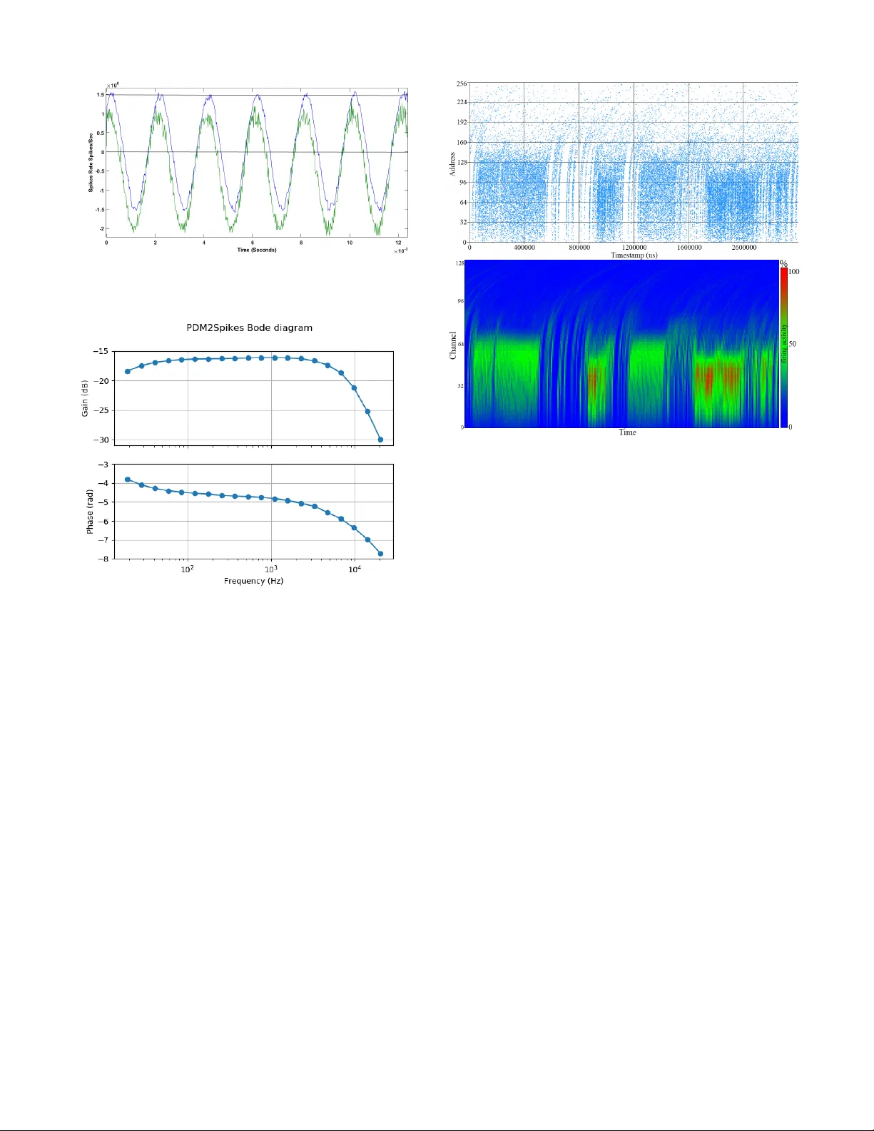
JOURNAL OF L A T E X CLASS FILES, VOL. 14, NO. 8, A UGUST 2015 1 Interfacing PDM MEMS microphones with PFM spiking systems: Application for Neuromorphic Auditory Sensors A. Jimenez-Fernandez, D. Gutierrez-Galan, A. Rios-Nav arro, J. P . Dominguez-Morales and G. Jimenez-Moreno Abstract —In neur omorphic engineering, computation is com- monly perf ormed asynchronously , mimicking the way in which nervous systems process information: spike by spike. The Neu- romor phic A uditory Sensor (NAS) has been implemented under this principle: applying different spike-based Signal Processing blocks. Computation in the spike domain requir es the con version of signals from analog or digital r epresentation to the spike domain, which could present a speed constraint in many cases. This paper presents a spike-based system to con v ert audio information from low-power pulse density modulation (PDM) MicroElectr oMechanical Systems (MEMS) micr ophones into rate coded spike frequencies. These spikes repr esent the input signal of the NAS, avoiding the analog or digital to spike con version, and ther efor e impr oving the time r esponse of the N AS. This con version has been done in VHDL as an interface for PDM microphones, converting their pulses into temporal distributed spikes follo wing a pulse frequency modulation (PFM) scheme with an accurate Inter-Spik e-Interval, known as ”PDM to spikes interface” (PSI). This was tested in two scenarios, first as a stand-alone circuit for its characterization, and then integrated with a NAS f or verification. The PSI achieves a T otal Harmonic Distortion (THD) of -39.51dB and a Signal-to-Noise Ratio (SNR) of 59.12dB, demands less than 1% of the r esources of a Spartan-6 FPGA and has a power consumption below 5mW . Index T erms —neuromor phic engineering, FPGA, Address- Event, pulse fr equency modulation, pulse density modulation, neuromor phic auditory sensor . I . I N T RO D U C T I O N Pulse-density modulation (PDM) is a sigma-delta modula- tion technique used to digitize an analog signal with a 1-bit data stream and a high sample rate. In recent years, many low-po wer microelectromechanical (MEMS) microphones de- signed for mobile applications, such as tablets, laptops and cell phones, among others, hav e appeared in the market. In PDM data streams, a logic 1 corresponds to a pulse of the maximum positive polarity (+A), and a logic 0 represents the maximum ne gativ e polarity (-A). A signal value of 0 is codified by an alternation of 1s and 0s. Commonly , this type of modulation is associated with neuromorphic information codification, in the sense of being a rate-coded signal [1]. This This work has been submitted to the IEEE for possible publication. Copyright may be transferred without notice, after which this version may no longer be accessible. This work was supported by the Spanish grant (with support from the European Regional De velopment Fund) COFNET (TEC2016-77785-P). The work of Daniel Gutierrez-Galan was supported by a Formaci ´ on de Personal In vestigador Scholarship from the Spanish Ministry of Education, Culture and Sport. All authors are with the Uni versidad de Sevilla,ETS Ingenieria Informatica. A vd. Reina Mercedes s/n, Sevilla, Spain (e-mail: angel@us.es). kind of computation allo ws processing information only when it is needed, avoiding periodic or redundant data processing, thus saving power and computational resources [2]. Currently , we can find di verse neuromorphic cochleae, both analog [3][4][5][6] and digital [7], [8], inspired by L yons cascade model [9] modeling the inner-hair cells (IHC). In [10], a Neuromorphic Auditory Sensor (N AS) is presented, based on spike signals processing (SSP) techniques [11][12]. Fig. 1 shows a global scheme of the NAS architecture. First, the audio information is provided by a digital audio codec, whose discrete audio samples output is conv erted into spike streams, follo wing the pulse frequenc y modulation (PFM). The N AS filters these spikes directly , spike after spike, using a set of Spike-based Lo w-Pass Filters (SLPF) connected in a cascade fashion. Finally , spikes are transmitted to the next layers using the Address-Event Representation (AER) protocol [13]. N AS has been currently used for man y practical applica- tions, as pitch frequency detection [14], musical tones iden- tification [15], sound source localization [16], heart murmurs diagnosis [17], and speech recognition [18], among others. Great ef fort has been dedicated to improv e N AS features, as it is the input layer of all these systems, improving responses and spreading for ne w applications of this technology . One main disadvantage of the N AS is the need for a discrete audio codec to capture analog audio. Audio codecs pro vide a set of digital periodic samples that must be con verted into spikes. These devices hav e a sampling period from 22.67 µ s to 10.41 µ s, limiting the temporal capabilities, e.g., sound localization applications. [19]Howe ver , PDM microphones provide a stream of rate-coded signals with higher sample rate (3.125MHz in this case, with a time resolution of 320ns), which can represent the N AS input and be directly processed as spiking information. Therefore way , the need to generate spike streams synthetically is avoided, which was a restriction in pre vious N AS implementations [10]. I I . P D M TO S P I K E S I N T E R F A C E ( P S I ) PDM information codification is substantially different from rate-coded spike-based signals. In rate-coded spike-based sig- nals, the information is given by the spikes frequency , which means that the information is in versely proportional to the tem- poral Inter-Spik e-Interval (ISI). This means that, with only tw o spikes, it is possible to reconstruct the amplitude of the original signal. Spike-based systems use PFM to distribute the spikes JOURNAL OF L A T E X CLASS FILES, VOL. 14, NO. 8, A UGUST 2015 2 A u d i o In p u t S p i k e - ba s e d F i l t e r B a nk – R ( N cha n ne l s ) Sp i ke s O u tp u t In ter f a c e S p i k e - ba s e d F i l t e r B a nk – L ( N chan n e l s ) AE R O ut pu t A u d io L in k C H . 0 C H . N - 1 C H . 0 C H . N - 1 C H . 0 C H . N - 1 C H . N C H . ( 2 *N ) - 1 ... ... ... ... FP G A A u d i o t o S p i k es f r o n t - en d R - S p i k es L - S p i k es Fig. 1: N AS Architecture: Audio to spikes, spikes processing banks, and AER output interface. in time properly , in order to accurately represent the signal’ s information. In PDM signals, the information is contained in the density of pulses, and one pulse is generated e very clock cycle, where a logic ’1’ represents a positive v alue, and a logic ’0’ a negati ve one. For example, when there are more 1s than 0s the information is positiv e, and the more 1s, the higher the amplitude is. Thus, for reconstructing the signal’ s amplitude, it is necessary to collect PDM pulses during a temporal window , performing a do wnsampling operation. Digital systems con vert PDM signals to digital values using the pulse coded modulation (PCM). PCM is reconstructed from PDM with a digital decimation stage, commonly per- forming a downsampling by a factor of 64, and providing a multiple-bits word (e.g., 16 bits @ 48.8kSamples/s) with high frequenc y noise added. After this stage, an infinite impulse response (IIR) filter is commonly used as a band-pass filter (BPF) to remov e DC components and high frequency quantization noise. The main goal of this work is to design an HDL circuit able to read PDM pulses and redistribute them in time as rate-coded spikes, with an ISI proportional to the sound pressure. Fig. 3 briefly shows how signals ev olve from PDM pulses to PFM spikes. T o con vert PDM information into rate-coded spikes, a two stages circuit (Fig. 2) is proposed. The first stage is a finite state machine (FSM) circuit that works as an edge detector , and generates a spike of a single clock cycle for each PDM pulse. The next stage consists in one (monaural) or two (binaural) banks of spike-based band-pass filters (SBPF), which process raw spikes from the FSM to giv e a temporal distributed spikes stream. Since spikes can be both positi ve and negati ve, we use two wires to represent signed spikes. The FSM output generates a stream of signed spikes that are still not distributed in time, with the ISI being constant and equal to the PDM clock period. Fig. 3 presents an example of a positiv e increasing audio signal, and ho w spikes e volv e. S p i k e - b a s ed B a n d P a s s F i l t er ( R ) P D M C l o c k G e n e r a t o r P D M E d g e d ec t ec t o r L R P D M C L K P D M D A T L & R S p i k e - b a s ed B a n d P a s s F i l t er ( L ) P D M C L K P D M D A T P F C O U T ( P ) P F C O U T ( N ) S BP F O U T ( P ) S BP F O U T ( N ) P F C O U T ( R) P F C O U T ( L ) S BP F O U T ( R) S BP F O U T ( L ) Fig. 2: PDM to spikes interface circuit. S p i k e - b a s ed B a n d P a s s F i l t er ( R ) P D M C l o c k G e n e r a t o r P D M E d g e d ec t ec t o r L R P D M C L K P D M D A T L & R S p i k e - b a s ed B a n d P a s s F i l t er ( L ) P D M C L K P D M D A T P F C O U T ( P ) P F C O U T ( N ) S BP F O U T ( P ) S BP F O U T ( N ) P F C O U T ( R) P F C O U T ( L ) S BP F O U T ( R) S BP F O U T ( L ) Fig. 3: Filtered spikes ev olving from an increasing PDM audio signal. A. PDM fr ont-end cir cuit The PDM front-end circuit (PFC) has two main function- alities: to generate the PDM clock and to con vert long PDM pulses into one clock cycle spikes. The hardware platform used to implement these blocks is called AER-Node [20] and it has a clock frequency of 50MHz. Dividing this clock by a factor of 16, we get a PDM clock of 3.125MHz, which is the maximum v alue allo wed by this kind of MEMS microphones. In e very PDM clock c ycle there is a PDM pulse in the PDM D A T line. If PDM D A T has a value of 1 then a positiv e spike is transmitted to the next stage, and if there is a 0 it will be a negati ve spike. B. Second-order Spikes Band-P ass F ilter (SBPF) The next stage is a Spike Band-Pass Filter (SBPF), whose functionality is detailed in [21]. This filter is composed of two first-order Spik e-based Lo w-pass filters (SLPF) and one Spike Hold & Fire (SH&F) (see Fig. 4). SH&F is a SSP building block that subtracts the spike rate between two spiking signals (detailed in [12]). The SLPF that is connected to the SH&F’ s positiv e input has a cut-off frequency that is higher than the SLPF connected to the negati ve input. Subtracting the output from both spik e-based filters, only the information in the middle band remains, rejecting the DC and high-frequency components. These filters are connected with 2-bit buses (for positiv e and negati ve spikes). These blocks use positiv e and negati ve activity to represent the bipolar nature of audio. S L P F L o w f r eq S p i k e s O u t S H & F - + S H & F - + S L P F Hi g h f r eq S p i k e s I n S P B F 2 2 2 2 Fig. 4: Spike Band-Pass Filter (SBPF) internal blocks. JOURNAL OF L A T E X CLASS FILES, VOL. 14, NO. 8, A UGUST 2015 3 C. Hardwar e resour ces and power consumption The PSI design was synthesized and implemented on a Xilinx Spartan 6 FPGA (XC6LX150T) to measure the required resources and its power consumption. T able I presents the resources that are needed to implement PSI in FPGA. As can be seen, the amount of resources needed is under 0.45% of the total slice re gisters and logic (LUT) of the FPGA. The PSI can operate at a clock frequency up to 147.18 MHz. After the synthesis, the power consumption was simulated using Xilinx XPower tool assuming a 50% of signal transitions, obtaining a po wer consumption estimation of 2.67mW for the PSI. This power consumption should be added to the MEMS microphones’ po wer , which depends on the ones that are used. In our case, each of the microphones demands 0.98mW (according to the documentation provided by the manufacturer). Therefore, the whole system demands a total of 4.63mW for a binaural NAS. T ABLE I: PSI hardware requirements Post-implementation results (Spartan 6 - XC6SLX150T) Slices Registers (%) Slices LUT (%) Max Clock F req. 204 / 184.304 (0.11%) 409 / 92.152 (0.44%) 147.18 MHz I I I . E X P E R I M E N T A L S E T U P For testing purposes, a scenario was built to analyze the PSI’ s standalone beha vior . Fig. 5 presents the testing setup, where two PDM microphones from ST Microelectron- ics (MP34DT02) were connected to an AER-Node board, which was in turn connected to an USB-AERmini2 board. MP34DT02 are omnidirectional MEMS microphones with PDM interf aces, with an acoustic o verload point of 120dB SPL , an SNR of 60dBm, a dynamic range of 86dB, and a maximum power consumption of 0.98mW (as pre viously described). A E R B U S U S B - A E R m i ni 2 P D M _C L K R L P D M _D A T A E R - N O D E S P A R T A N 6 F P G A 1 m e t e r P D M M i c s P D M _C L K P D M _D A T U SB F l a t r es p o n s e s p ea k er Fig. 5: T est scenario. Sound is played by a response speaker , exciting PDM microphones. Finally , the information is sent to a computer through an AER-to-USB interface. The AER-Node board has a Xilinx Spartan 6 FPGA (XC6S150T), which holds the PSI, a 128-channel binaural N AS, and a set of AER interfaces. Its parallel AER output was connected to the USB-AERmini2 board [22], which works like a bridge between AER b uses and USB ports, allowing the AER events to be sent from the AER-Node board to a host computer . In the computer, two software tools were running: jAER [23], to visualize and log AER information; and MA TLAB, to analyze and process the e vents. The sound used to excite the system w as played using a flat response audio speaker , in this case a BEHRITONE C5A from Behringer, placed at a 1-meter distance from the PDM microphones and at a fix ed gain in order to ha ve an audio level of 65dBSPL on the microphones’ side. This kind of equipment was used to av oid the influence of audio equalizers and the compensation that domestic Hi-Fi equipment presents. Thus, no preprocessed sounds were used and, instead, we tried to reproduce sound wa ves in the most ideal way possible. This will potentially open our system to many stand-alone applications, such as robotics. A. PSI Experimental r esults For the first experiment, the system was stimulated with a clear 500Hz pure tone audio signal played by the flat response speaker . Fig. 6 repres ents the spikes from each stage of the PSI. Higher addresses (3 and 2) correspond to the spikes fired by the PDM front-end circuit, and lower addresses (1 and 0) to the SPBF output. Spike addresses 3 and 1 are positiv e, whilst 2 and 0 are negativ e. Fig. 6: Spikes from PSI: PDM front-end output (3-2) (top), and PSI’ s output (1-0) after filtering (bottom). Fig. 6 depicts how the addresses that contain the output of the PDM front-end overlap the information between positive and negati ve, which does not happen after filtering it with the PSI. In PDM, information makes sense for the average acti vity of a temporal window . Howe ver , in the spikes domain, the information is coded with the time between two consecuti ve spikes. From the signal sign point of view , we can say that zero-crossing is performed when the polarity of the spikes changes(i.e. after a positive spike, a ne gativ e one is produced). In the case of the PDM front-end output, there are several spikes overlapping positive (address 3) and negati ve activity (address 2). From the point of view of ISI, this represents a considerable amount of high-frequency noise. Ho wev er , if we check the SBPF output spikes, there is no overlapping between positiv e (address 1) and neg ativ e (address 0) acti vity , rejecting high frequency noise. Fig. 7 sho ws the reconstruction of the original signal using the spik es’ ISI. First, the green signal represents the recon- struction from PDM front-end’ s output. This is a noisy signal and it has an offset introduced by the PDM microphones. On the other hand, the blue signal is the reconstruction from SBPFs output. A clear tone with neither noise nor of fset can be seen, improving the previous audio signal quality . Analyzing this response, we achieve a T otal Harmonic Distortion (THD) of -39.51dB and a Signal-to-Noise Ratio (SNR) of 59.12dB. JOURNAL OF L A T E X CLASS FILES, VOL. 14, NO. 8, A UGUST 2015 4 Fig. 7: T emporal reconstruction of a 500Hz tone. Green: PDM front-end’ s output. Blue: SBPF’ s output. Fig. 8: Bode diagram of the PDM2Spikes module. T o measure the number of zero-crossings, a one second recording w as analyzed and the amount of changes from positiv e spike to negativ e and vice versa were counted. In the PDM front-end’ s output, more than 80k zero-crossings were found. Howe ver , in SBPF’ s output, 1k zero-crossings were found, which exactly matches a 500Hz signal. Our second experiment consisted in a frequency sweep from 20Hz to 20KHz to analyze the behavior of the system with different frequencies. Fig. 8 shows the frequenc y sweep results as a bode diagram. The top curve in Fig. 8 presents the gain for div erse frequencies. PSI gain starts to increase from 70Hz to 12KHz, and then decreases rejecting higher frequencies. This bandwidth is enough for many applications related to speech and speakers recognition. The spike-based filters in the PSI introduce a temporal de viation. It was measured as signal phase (in rads) and the results are included in Fig. 8 bottom. PSI has a mean phase of -4.5 rads, approximately , increasing when frequency is close to the cut-off frequency , as e xpected from a lo w-pass filter . B. NAS integr ation In order to v alidate the PSI on a real scenario, it was integrated in a 128-channel binaural N AS. This N AS was fed with a male voice saying: “Si vis pacem, para bellum”, and the Fig. 9: Cochleogram (top) and sonogram (bottom) obtained with N A VIS from a speaker saying “Si vis pacem para bellum”. output activity was recorded using an USB-AERMini2 board as an AER-DA T A file. Fig.9 contains the cochleogram and the sonogram of this recording, respectiv ely . Each word is clearly distinguishable, and acti v ates middle channels between 200Hz and 5kHz. These figures were obtained by using N A VIS software [24]. I V . C O N C L U S I O N S In this paper , a PDM to PFM Spikes circuit is presented. PDM MEMS microphones are useful for lo w-power , stand- alone, embedded applications. Their output is based on spike density , and it needs to be adapted in order to be used as input to the NAS. A two-stage circuit for FPGA was designed, which is able to conv ert PDM information to PFM spikes with a consistent ISI. The PSI was synthesized for a Spartan 6 FPGA with low resources and power requirements. It was then tested with real audio stimulus, analyzing its behavior in terms of temporal response and zero-crossings. The PSI was also integrated in a full NAS to demonstrate the viability of the combination of this kind of systems. The use of PDM microphones with NAS considerably simplifies the system, enabling compact and portable spike-based auditory systems with lo wer power consumption. R E F E R E N C E S [1] L. S. Smith, “Neuromorphic systems: past, present and future, ” in Br ain Inspir ed Cognitive Systems 2008 . Springer , 2010, pp. 167–182. [2] S. Liu, B. Rueckauer, E. Ceolini, A. Huber, and T . Delbruck, “Event- driv en sensing for efficient perception: V ision and audition algorithms, ” IEEE Signal Processing Magazine , vol. 36, no. 6, pp. 29–37, Nov 2019. [3] V . Chan, S.-C. Liu, and A. van Schaik, “ Aer ear: A matched silicon cochlea pair with address ev ent representation interface, ” IEEE T rans- actions on Cir cuits and Systems I: Regular P apers , v ol. 54, no. 1, pp. 48–59, 2007. JOURNAL OF L A T E X CLASS FILES, VOL. 14, NO. 8, A UGUST 2015 5 [4] T . J. Hamilton, C. Jin, A. V an Schaik, and J. T apson, “ An activ e 2-d silicon cochlea, ” IEEE Tr ansactions on biomedical circuits and systems , vol. 2, no. 1, pp. 30–43, 2008. [5] B. W en and K. Boahen, “ A silicon cochlea with activ e coupling, ” IEEE transactions on biomedical circuits and systems , vol. 3, no. 6, pp. 444– 455, 2009. [6] S.-C. Liu, A. V an Schaik, B. A. Mincti, and T . Delbruck, “Ev ent-based 64-channel binaural silicon cochlea with q enhancement mechanisms, ” in Pr oceedings of 2010 IEEE International Symposium on Cir cuits and Systems . IEEE, 2010, pp. 2027–2030. [7] C. Mugliette, I. Grech, O. Casha, E. Gatt, and J. Micallef, “Fpga active digital cochlea model, ” in 2011 18th IEEE International Confer ence on Electr onics, Circuits, and Systems . IEEE, 2011, pp. 699–702. [8] C. S. Thakur , T . J. Hamilton, J. T apson, A. van Schaik, and R. F . L yon, “Fpga implementation of the car model of the cochlea, ” in 2014 IEEE International Symposium on Cir cuits and Systems (ISCAS) . IEEE, 2014, pp. 1853–1856. [9] R. L yon, “ A computational model of filtering, detection, and compres- sion in the cochlea, ” in ICASSP’82. IEEE International Conference on Acoustics, Speech, and Signal Processing , vol. 7. IEEE, 1982, pp. 1282–1285. [10] A. Jim ´ enez-Fern ´ andez, E. Cerezuela-Escudero, L. Mir ´ o-Amarante, M. J. Dom ´ ınguez-Morales, F . de As ´ ıs G ´ omez-Rodr ´ ıguez, A. Linares- Barranco, and G. Jim ´ enez-Moreno, “ A binaural neuromorphic auditory sensor for fpga: A spik e signal processing approach, ” IEEE tr ansactions on neural networks and learning systems , vol. 28, no. 4, pp. 804–818, 2016. [11] A. Jimenez-Fernandez, A. Linares-Barranco, R. Paz-V icente, G. Jim ´ enez, and A. Civit, “Building blocks for spikes signals processing, ” in The 2010 International J oint Confer ence on Neural Networks (IJCNN) . IEEE, 2010, pp. 1–8. [12] A. Jimenez-Fernandez, G. Jimenez-Moreno, A. Linares-Barranco, M. J. Dominguez-Morales, R. Paz-V icente, and A. Civit-Balcells, “ A neuro- inspired spike-based pid motor controller for multi-motor robots with low cost fpgas, ” Sensors , v ol. 12, no. 4, pp. 3831–3856, 2012. [13] K. A. Boahen, “Point-to-point connectivity between neuromorphic chips using address ev ents, ” IEEE T ransactions on Circuits and Systems II: Analog and Digital Signal Pr ocessing , vol. 47, no. 5, pp. 416–434, 2000. [14] J. P . Dominguez-Morales, A. Jimenez-Fernandez, A. Rios-Navarro, E. Cerezuela-Escudero, D. Gutierrez-Galan, M. J. Dominguez-Morales, and G. Jimenez-Moreno, “Multilayer spiking neural network for audio samples classification using spinnaker , ” in International Confer ence on Artificial Neural Networks . Springer, 2016, pp. 45–53. [15] E. Cerezuela-Escudero, A. Jimenez-Fernandez, R. Paz-V icente, J. P . Dominguez-Morales, M. J. Dominguez-Morales, and A. Linares- Barranco, “Sound recognition system using spiking and mlp neural networks, ” in International Conference on Artificial Neural Networks . Springer , 2016, pp. 363–371. [16] T . Schoepe, D. Gutierrez-Galan, J. P . Dominguez-Morales, A. Jimenez- Fernandez, A. Linares-Barranco, and E. Chicca, “Neuromorphic sen- sory integration for combining sound source localization and collision av oidance, ” in 2019 IEEE Biomedical Circuits and Systems Confer ence (BioCAS) . IEEE, 2019, pp. 1–4. [17] J. P . Dominguez-Morales, A. F . Jimenez-Fernandez, M. J. Dominguez- Morales, and G. Jimenez-Moreno, “Deep neural netw orks for the recog- nition and classification of heart murmurs using neuromorphic auditory sensors, ” IEEE transactions on biomedical cir cuits and systems , vol. 12, no. 1, pp. 24–34, 2017. [18] J. P . Dominguez-Morales, Q. Liu, R. James, D. Gutierrez-Galan, A. Jimenez-Fernandez, S. Davidson, and S. Furber , “Deep spiking neural network model for time-v ariant signals classification: a real-time speech recognition approach, ” in 2018 International Joint Confer ence on Neural Networks (IJCNN) . IEEE, 2018, pp. 1–8. [19] G. Indi veri and Y . Sandamirskaya, “The importance of space and time for signal processing in neuromorphic agents: The challenge of develop- ing low-power , autonomous agents that interact with the en vironment, ” IEEE Signal Processing Magazine , vol. 36, no. 6, pp. 16–28, Nov 2019. [20] T . Iakymchuk, A. Rosado, T . Serrano-Gotarredona, B. Linares-Barranco, A. Jim ´ enez-Fernandez, A. Linares-Barranco, and G. Jim ´ enez-Moreno, “ An aer handshake-less modular infrastructure pcb with x8 2.5 gbps lvds serial links, ” in 2014 IEEE International Symposium on Cir cuits and Systems (ISCAS) . IEEE, 2014, pp. 1556–1559. [21] M. Dom ´ ınguez-Morales, A. Jimenez-Fernandez, E. Cerezuela-Escudero, R. Paz-V icente, A. Linares-Barranco, and G. Jimenez, “On the designing of spikes band-pass filters for fpga, ” in International Conference on Artificial Neural Networks . Springer, 2011, pp. 389–396. [22] R. Berner, T . Delbruck, A. Civit-Balcells, and A. Linares-Barranco, “ A 5 meps $100 usb2. 0 address-event monitor -sequencer interface, ” in 2007 IEEE International Symposium on Cir cuits and Systems . IEEE, 2007, pp. 2451–2454. [23] T . Delbruck, “Frame-free dynamic digital vision, ” in Proceedings of Intl. Symp. on Secure-Life Electronics, Advanced Electronics for Quality Life and Society . T okyo, 2008, pp. 21–26. [24] J. P . Dominguez-Morales, A. Jimenez-Fernandez, M. Dominguez- Morales, and G. Jimenez-Moreno, “Navis: neuromorphic auditory vi- sualizer tool, ” Neur ocomputing , vol. 237, pp. 418–422, 2017.
Original Paper
Loading high-quality paper...
Comments & Academic Discussion
Loading comments...
Leave a Comment