Framework for High-performance Video Acquisition and Processing in MTCA.4 Form Factor
The video acquisition and processing systems are commonly used in industrial and scientific applications. Many of them utilize Camera Link interface for the transmission of a video stream from the camera to the host system. The framework presented in…
Authors: Aleks, er Mielczarek, Dariusz Makowski
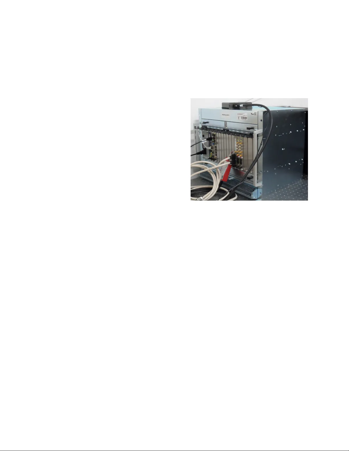
1 Frame work for High-performance V ideo Acquisition and Processing in MTCA.4 F orm F actor A. Mielczarek, D. Mako wski, Member , IEEE , P . Perek, A. Napieralski, Senior Member , IEEE I . I N T RO D U C T I O N The video acquisition and processing systems are commonly used in industrial and scientific applications. Many of them utilize Camera Link interface for the transmission of a video stream from the camera to the host system. The framew ork presented in the paper enables capturing such data, processing it and transmitting to the host CPU. It consist of MTCA.4- compliant frame grabber and a set of software libraries sup- porting se veral dif ferent cameras. It is designed for use in large scale physics experiments such as ITER tokamak or European X-Ray Free-Electron Laser (E-XFEL), as well as in the Centre for Free-Electron Laser Science (CFEL). I I . M T C A . 4 The base MTCA.0 specification allo ws building high- throughput telecommunication solutions, but is not ideally suited for Data Acquisition (DA Q) systems. Although the MCH usually allows advanced routing of the clock signals, the infrastructure for distributing synchronization and trigger signals is limited. Additionally , there is no possibility of connecting the cables from the rear side of the shelf – which is a recommended practice in many applications. All the cables hav e to enter the modules through the front panel often reducing accessibility of the neighboring modules [1]. All the aforementioned issues were addressed in the MTCA.4 subsidiary specification "MicroTCA enhancement for rear I/O and precision timing". A typical MTCA.4- compliant crate is presented in Figure 1. The MTCA.4 specification defines an M-L VDS bus con- necting all the AMC slots which allows easy distribution of system-wide signals, like timing events or interlocks. It also introduces concept of a Rear Transition Module (R TM) – a second PCB closely cooperating with the AMC module. Such a module not only ef fectively doubles the av ailable PCB space but also allo ws connecting the cables in the rear of the shelf [2]. I I I . H A R DWA R E P L A T F O R M The commercially av ailable MFG4 solution was selected as target platform for the frame grabber infrastructure ref- erence implementation. It is composed of a dual slot FMC carrier board and of Camera Link pass-through modules. The carrier card is a double width AMC module with a recent 7-Series Xilinx Artix FPGA. Depending on the option, it is A. Mielczarek, D. Mako wski, P . Perek, A. Napieralski, are with the Lodz Univ ersity of T echnology , Poland (e-mail: amielczarek@dmcs.pl) Fig. 1. A typical MTCA.4 12-slot chassis accompanied with one or two FMC Camera Link modules. The deserialization is meant to be done directly in the FPGA, thus no external active circuits are needed. The MFG4 base board is equipped with a 2 GB SDRAM buf fer consisting of four 16-bit DDR3 chips. The 64-bit DDR bus can operate at 533 MHz of fering a throughput of 68.2 Gb/s. This is more than twice the throughput required to support two cameras outputting video at the maximum possible data rate supported by the Camera Link standard (full configuration, 80-bit mode). I V . T H E F P G A F R A M E W O R K Although the Camera Link standard was first released in 2000, it is still commonly used in high-speed cameras. The most ef ficient 80-bit mode of operation allows 80 bits of data plus 4 synchronization signals to be transmitted in e very clock cycle. The clock frequency is limited by the standard to 85 MHz. The data to be transmitted is split into three groups of 28 bits and serialized. Each group is transmitted over 4 data lines accompanied by a clock signal, following the Channel Link protocol. Receiving a Camera Link data is not trivial, as the link is composed of three independent, possibly asynchronous, channels. Therefore, each channel has to be buffered in the receiv er and then synchronized with the others. The Camera Link standard defines a variety of mappings between pixel data and link words. Rearrangement of the incoming data is partly done in firmware and partly in software due to a large number of possible configurations. The video data is captured by the Camera Link receiv er and transferred via an AXI Stream interface. The video stream is then directed to the Xilinx V irtual FIFO (VFIFO). It is an IP- Core which helps implement FIFO queues based on external memories. The virtual FIFO is a very helpful component, howe ver it also has some drawbacks. For instance, it can only control relatively small memory regions (up to several tens of MB). Moreover , it cannot emit a warning when the amount of av ailable storage space drops below a certain limit. Therefore, a dedicated monitoring component was dev eloped to asses if the next frame will fit in the memory or not. During write of the captured data to the VFIFO the frame resolution is identified and a corresponding timestamp is cap- tured. This information, along with user supplied meta-data, are stored into a frame information FIFO. The synchronization signals form the camera are not stored in the VFIFO. These are ho wever , crucial for further data processing. Moreo ver , the processing algorithms should hav e the information on the image resolution in advance. T o accommodate for these features, the frame reader module was dev eloped. Firstly , it reads the information on frame resolution and then reads the actual frame data from the VFIFO. It is able to fetch just the right amount of data from the memory and regenerate the synchronization signals. W ith each retriev ed frame the module provides information on its resolution, number , timestamp, etc. Fig. 2. Block diagram of the FPGA firmware Before the data is stored in the host memory , each captured and processed frame has to be appended with a header . The headers are generated by the TIFF header provider . The TIFF format was selected mainly due to its straightforward file structure and support for uncompressed gray-scale images. The video stream is written to the host computer memory by a custom DMA engine dev eloped at the Department of Micro- electronics and Computer Science (DMCS) of Lodz Uni versity of T echnology . The engine supports efficient transfers utilizing a scatter-gather list. The camera is controlled and monitored through a simple U AR T interface. The physical layer is defined by the Camera Link specification, whereas the frame format and particular command set is vendor dependent. V . S O F T W A R E S U P P O RT The frame work also includes complete software support consisting of Linux device driver , API libraries as well as console and graphical user applications. The Linux device driv er implements two independent interfaces: one for high- performance image acquisition and the other for camera con- trol using U AR T interface defined in the Camera Link stan- dard. The driv er fully supports the DMA engine implemented in the FPGA firmware and ensures efficient data transfer from the FPGA buf fer directly to user -space memory [3]. T o facil- itate software development the framework also provides set of API libraries. The lo w-le vel library communicates directly with the device driv er and provides easy-to-use functions for image data reading and sending/receiving characters via the U AR T interface. The higher-le vel libraries implement control protocols defined for particular cameras. Usually single library is dedicated for specific camera or group of cameras sharing the same control protocol. Thanks to such approach, the framew ork can be easily extended to support new cameras. The only effort necessary for communication with ne w device is development of camera library implementing its control protocol. The highest layer of the software support are console and graphical applications. All of them use camera-specific libraries for communication with the hardware. The console applications pro vide easy access to current settings and status information, control of the camera and image acquisition. The graphical applications additionally offer data visualiza- tion (both liv e previe w and off-line data display) and basic processing. Graphical user interface allo ws con venient camera configuration, data acquisition, recording and analysis. V I . P RO O F O F C O N C E P T S Y S T E M The dev eloped framew ork enables collecting the data from the camera using the top performance 80-bit mode of the Full Camera Link interface, offering 6.8 Gb/s of raw im- age data throughput. The solution was tested with a num- ber of commercially av ailable cameras, including: Mikrotron MC3010/MC3011, PCO EDGE 5.5, Andor NEO 5.5, Basler Sprint spL2048-70km. V I I . C O N C L U S I O N The proposed video acquisition solution features the worlds first Camera Link frame grabber for the MTCA.4 architecture. MFG4 card was chosen due to its fair cost to performance balance and provision of a Xilinx 7-Series FPGA. Thanks to the modern FPGA circuit architecture, the deserialization is done using only the built-in ISERDES primitives, which reduces the costs and complexity of the required hardware. The implemented deserializer is capable of supporting all the Camera Link modes and configurations. Especially , it allows capturing the Full Camera Link 80-bit image data with reference clock of 85 MHz, which constitutes the highest data rate supported by the standard. R E F E R E N C E S [1] PICMG, “Micro T elecommunications Computing Architecture, ” July 2006. [2] ——, “MicroTCA Enhancements for Rear I/O and Precision Timing, ” August 2011. [3] P . Perek, “High-performance image processing system for plasma diag- nostics, ” in Pr oceedings of the XV International PhD W orkshop OWD , 2013, pp. 328–331.
Original Paper
Loading high-quality paper...
Comments & Academic Discussion
Loading comments...
Leave a Comment