Adaptive neural network based dynamic surface control for uncertain dual arm robots
The paper discusses an adaptive strategy to effectively control nonlinear manipulation motions of a dual arm robot (DAR) under system uncertainties including parameter variations, actuator nonlinearities and external disturbances. It is proposed that…
Authors: Dung Tien Pham, Thai Van Nguyen, Hai Xuan Le
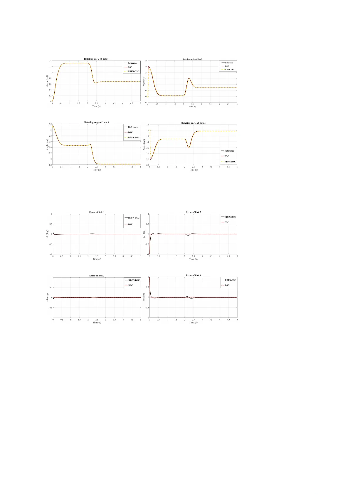
Noname man uscript No. (will b e inserted b y the editor) Adaptiv e neural net w ork based dynamic surface con trol for uncertain dual arm robots Dung Tien Pham · Thai V an Nguyen · Hai Xuan Le · Linh Nguy en · Nguy en Huu Thai · T uan Anh Phan · Hai T uan Pham · Anh Hoai Duong Received: date / Accepted: date Abstract The pap er discusses an adaptiv e strategy to effectiv ely con trol non- linear manipulation motions of a dual arm rob ot (D AR) under system uncer- tain ties including parameter v ariations, actuator nonlinearities and external disturbances. It is proposed that the control sc heme is first deriv ed from the dynamic surface control (DSC) metho d, which allo ws the rob ot’s end-effectors to robustly track the desired tra jectories. Moreov er, since exactly determining the D AR system’s dynamics is impractical due to the system uncertain ties, the uncertain system parameters are then prop osed to b e adaptiv ely estimated by the use of the radial basis function net w ork (RBFN). The adaptation mech- anism is deriv ed from the Lyapuno v theory , whic h theoretically guaran tees stabilit y of the closed-loop control system. The effectiveness of the proposed RBFN-DSC approach is demonstrated by implementing the algorithm in a syn thetic environmen t with realistic parameters, where the obtained results are highly promising. Keyw ords Dynamic surface con trol · Sliding mo de con trol · Dual arm robot · Radial basis function · Ly apunov metho d. 1 In tro duction Rob ots hav e b een increasingly mo ving into human based en vironmen ts to re- place or assist h uman w orkers. More sp ecifically , anthropomorphic or dual L. Nguy en Centre for Autonomous Systems, University of T echnology , Sydney , New South W ales 2007, Australia T el.: +61-2-95141225 F ax: +61-2-95142655 E-mail: v anlinh.nguyen@uts.edu.au D. T. Pham, T. V. Nguy en, H. X. Le, N. H. Thai, T. A. Phan, H. T. Pham and A. H. Duong Department of Automatic Control, Hanoi Universit y of Science and T ec hnology , Hanoi 10000, Vietnam 2 Dung Tien Pham et al. arm rob ots (DAR) ha v e more and more play ed a vital role in many industrial, health care or household environmen ts [1, 2, 3, 4, 5, 6]. F or instance, dual arm manipulators hav e been effectiv ely employ ed in a diversit y of tasks including assem bling a car, grasping and transp orting an ob ject or n ursing the elderly [7]. In those scenarios, the DAR hav e b een expected to behav e like a h uman, whic h is they should be able to manipulate an ob ject similarly to what a person do es [3]. As compared to a single arm rob ot, the DAR hav e significan t adv an- tages such as more flexible mov emen ts, higher precision and greater dexterity for handling large ob jects [8, 9]. Nev ertheless, since the kinematic and dynamic mo dels of the DAR system are muc h more complicated than those of a sin- gle arm rob ot, it has more challenges to effectively and efficiently con trol the D AR, where synchronously co ordinating the rob ot arms are highly exp ected. In order to accurately and stabily track the rob ot arms along desired tra- jectories, a num ber of the control strategies hav e b een prop osed. F or instance, the traditional metho ds suc h as nonlinear feedbac k con trol [10] or h ybrid force/p osition control relied on the kinematics and statics [11, 12] hav e b een prop osed to simultaneously con trol b oth of the arms. In the works [13, 14, 15], the authors hav e prop osed to utilize the imp edance con trol b y considering the dynamic in teraction betw een the robot and its surrounding environmen t while guaranteeing the desired mov emen ts. More imp ortantly , robustness of the control p erformance is also highly prioritized in consideration of designing a con troller for a highly uncertain and nonlinear DAR system. In literature of the mo dern control theory , sliding mo de control (SMC) demonstrates a di- v erse abilit y to robustly control an y system. Since the pioneer w ork [16], the v ariable structure SMC has enjoy ed widespread use and a tten tion in many applications [17, 18, 19, 20, 21, 22, 23, 24, 25, 26, 27, 28]. Nonetheless, due to pres- ence of discontin uities, the SMC la w may cause undesirable oscillations, whic h is also called the chatterring phenomenon. Park et al. [29] prop osed a satura- tion function to replace the discon tin uous sign um function in the control signal to reduce effects of the c hattering. Recently , the chattering phenomenon can b e eliminated by designing the controller without a discontin uous term [25, 26]. F or robustly controlling nonlinear systems with unmatched uncertainties, the SMC control law is usually designed in conjunction with the backstepping metho d, where the sliding surface is aggregated in the last step [30, 31]. F or instance, Chen et al. [32] developed a backstepping sliding mo de con troller to enhance the global ultimate asymptotic stability and in v ariabilit y to uncertain- ties in a nonholonomic wheeled mobile manipulator. T o address the problem of explosion of terms asso ciated with the integrator backstepping tec hnique, Sw aro op et al. [33] proposed the dynamic surface con trol (DSC) metho d by using a first-order lo w-pass filter in the synthetic input. Nonetheless, the aforesaid traditional control techniques are not really practical when they require to accurately mo del all the nonlinear dynam- ics of the DAR system, where its unknown parameters are highly uncertain and not easily estimated. It is noted that uncertainties of the DAR system can practically lead to degradation of its control performance. F urthermore, a num b er of unexp ected disturbances and obstacles in the working environ- Title Suppressed Due to Excessiv e Length 3 men ts can cause the DAR system to be unstable. T o address the issues of accurately mo delling all the nonlinear dynamics and estimating the unknown and uncertain parameters, some mo dern control approaches based on fuzzy logic or artificial neural netw ork hav e b een prop osed in the past decades. F or instance, by the use of the adaptiv e learning and function approximations, Lee and Choi [34] introduced a radial basis function netw ork (RBFN) for appro ximating the nonlinear dynamics of a SCARA-type robot manipulator. Similarly , W ang et al. [35] employ ed the appro ximation of a neural netw ork to deal with the nonlinearities and uncertainties of a single rob ot manipulator, where errors caused by the neural netw ork approximation can b e estimated b y a prop osed control robust term. In addition, the authors in [7] designed an adaptiv e con trol system for a h umanoid rob ot b y using the RBFN to develop a sc heme to adaptively estimate unknown and uncertain dynamics of the rob ot. Based on a multi-input m ulti-output fuzzy logic unit, Jiang et al. [36] pro- p osed an algorithm to adaptively estimate the dynamics of the DAM, giv en its nonsysmmetric deadzone nonlinearity . In the context of adaptive DSC, it w as prop osed to employ fuzzy techniques and neural net w orks to adaptiv ely estimate parameters for the control la ws in uncertain nonlinear systems [37] and nonlinear systems with uncertain time dela ys [38], resp ectively . In this paper, w e prop ose an adaptive control strategy based on the DSC metho d and the RBFN to effectively and efficien tly control the D AR system. The proposed approach pro vides the DAR system not only adaptive estima- tion of the nonlinear dynamics but also robustness to system uncertainties including the system parameter v ariations, actuator nonlinearities and exter- nal disturbances. In other w ords, the aggregated control sc heme based on the DSC technique enables the manipulators to b e capable of efficiently track- ing the desired tra jectories given large v ariation of the system information suc h as the undetermined volume and mass of the payload and significantly reducing chattering influences. The RBFN allows the proposed controller to b e able to adaptively estimate the nonlinear and uncertain parameters of the D AR system. More imp ortantly , the adaptation mechanism is designed based on Lyapuno v method, which mathematically guarantees the stabilit y of the closed-lo op con trol system. The prop osed algorithm was extensiv ely v alidated in the synthetic environmen ts, where the obtained results are highly promising. The rest of the pap er is arranged as follows. W e first introduce a mo del of the DAR system in Section 2. W e then present how to construct a RBFN- DSC controller for the D AR system based on the DSC and RBFN in Section 3. Section 4 discusses v alidation of the prop osed approac h in a sim ulation en vironment b efore conclusions are drawn in Section 5. 2 Dual Arm Rob ot Mo del Lets consider a dual tw o degree of free (DoF) arm rob ot that co op eratively manipulates an ob ject with mass of m as pictorically shown in Fig. 1. It is assumed that b oth the manipulators rigidly attach to the load so that there is 4 Dung Tien Pham et al. Fig. 1: Dual arm rob ot mo delling Fig. 2: Op erational motions of dual arm rob ot no slip b etw een the grasping p oints and the grasp ed load. Let m i , I i , l i denote the mass, mass moment of inertia and length of the corresp onding link in the mo del, resp ectively . W e also define d 1 and d 2 as the length of the ob ject and distance betw een the tw o arms at the rob ot’s base. The distance from the mass cen tre of a link to a joint is denoted as k i while the joint angle b etw een a link and the base or its preceding link is denoted as θ i . Title Suppressed Due to Excessiv e Length 5 Op erationally , in this work we consider that the rob ot manipulators make motions on the horizontal xy plane. In other words, the rob ot arms first mo v e to wards the ob ject. After the manipulators are firmly attac hed to the load, the rob ot then picks the ob ject up and transports it to a new position b y adjusting the motions to robustly follo w the given tra jectory , demonstrated in Fig. 2, where ( x i , y i ) and ( x f , y f ) are the initial and final lo cations of the payload, resp ectiv ely . W e let x m and y m denote the mass center of the payload on the xy plane, the tra jectory of the ob ject can b e sp ecified by x m = d 2 2 + l 1 cos θ 1 + l 2 cos( θ 1 + θ 2 ) − d 1 2 = − d 2 2 + l 3 cos θ 3 + l 4 cos( θ 3 + θ 4 ) + d 1 2 , y m = l 1 sin θ 1 + l 2 sin( θ 1 + θ 2 ) = l 3 sin θ 3 + l 4 sin( θ 3 + θ 4 ) . In order to transp ort the ob ject to a new p osition, the rob ot manipulators apply forces F 1 and F 2 to the payload as illustrated in Fig. 3. On the other hands, to rigidly hold the load up, friction forces F s 1 and F s 2 are needed. Let F siy and F siz denote the comp onen ts of the friction forces in y and z directions, respectively . T o prev en t the load from rotating around y and z axes, it is supp osed that F s 1 y = F s 2 y and F s 1 z = F s 2 z . Then the dynamic equations of the ob ject are as follows, m ¨ x m = F 2 − F 1 , m ¨ y m = 2 F s 1 y = 2 F s 2 y , mg = 2 F s 1 z = 2 F s 2 z , (1) where ¨ x m ( t ) = − L 1 ˙ θ 1 cos θ 1 + ¨ θ 1 sin θ 1 − L 2 ˙ θ 1 + ˙ θ 2 2 cos ( θ 1 + θ 2 ) − L 2 ¨ θ 1 + ¨ θ 2 2 sin ( θ 1 + θ 2 ) , (2) ¨ y m ( t ) = L 3 ¨ θ 3 cos θ 3 + ˙ θ 2 3 sin θ 3 − L 4 h ¨ θ 3 + ¨ θ 4 cos ( θ 3 + θ 4 ) i + L 4 ˙ θ 3 + ˙ θ 4 2 sin ( θ 3 + θ 4 ) , (3) and g = 9 . 8 m/s 2 . And the relationship b et ween the applied forces and the friction forces is presen ted by F s 1 y 2 + ( mg 2 ) 2 < ( µF 1 ) 2 , F s 2 y 2 + ( mg 2 ) 2 < ( µF 2 ) 2 , (4) where µ is the friction co efficien t in dry condition. 6 Dung Tien Pham et al. Fig. 3: Ph ysical mo del of the rob ot arms If ¨ x m ( t ) ≥ 0, b oth the applied forces F 1 and F 2 can b e computed b y F 1 = 1 µ r m ¨ y m 2 2 + mg 2 2 , F 2 = 1 µ r m ¨ y m 2 2 + mg 2 2 + m ¨ x m . (5) Nonetheless, if ¨ x m ( t ) < 0, those forces can b e obtained b y F 1 = 1 µ r m ¨ y m 2 2 + mg 2 2 − m ¨ x m , F 2 = 1 µ r m ¨ y m 2 2 + mg 2 2 . (6) By the use of Lagrange multipliers, the dynamic mo del of the dual arm rob ot manipulating the pa yload can b e summarized as follows, M ( θ ) ¨ θ + C ( θ , ˙ θ ) ˙ θ = u + J T ( θ ) F ( θ , ˙ θ , ¨ θ ) − T d − β , where u is a 4 × 1 control torque input vector, T d is a 4 × 1 vector presenting the noise effects on the rob ot arms and β denotes the viscous friction forces on all the join ts, which are sp ecified as follows, θ = θ 1 θ 2 θ 3 θ 4 T , u = u 1 u 2 u 3 u 4 T , F = F 1 F s 1 y F 2 F s 2 y T , T d = T d 1 T d 2 T d 3 T d 4 T , β = b 1 ˙ θ 1 b 2 ˙ θ 2 b 3 ˙ θ 3 b 4 ˙ θ 4 T , Title Suppressed Due to Excessive Length 7 where b i is the viscous friction at the i th join t. M ( θ ) is a 4 × 4 matrix of the mass momen t of inertia, whose comp onents are sp ecified by m 11 = A 1 + A 2 + 2 A 3 cos θ 2 , m 12 = m 21 = A 2 + A 3 cos θ 2 , m 22 = A 2 , m 13 = m 14 = m 23 = m 24 = 0 , m 33 = A 4 + A 5 + 2 A 6 cos θ 4 , m 34 = m 43 = A 5 + A 6 cos θ 4 , m 44 = A 5 , m 31 = m 32 = m 41 = m 42 = 0 with A 1 = m 1 k 2 1 + m 2 l 2 1 + I 1 , A 2 = m 2 k 2 2 + I 2 , A 3 = m 2 l 1 k 2 , A 4 = m 3 k 2 3 + m 4 l 2 3 + I 3 , A 5 = m 4 k 4 2 + I 4 , A 6 = m 4 l 3 k 4 . (7) C ( θ, ˙ θ ) is a 4 × 1 Coriolis-centripetal vector, whose elements are computed by c 11 = − A 3 sin θ 2 ( ˙ θ 2 2 + ˙ θ 1 ˙ θ 2 ) + b 1 ˙ θ 1 , c 21 = A 3 ˙ θ 2 1 sin θ 2 + b 2 ˙ θ 2 , c 31 = − A 6 sin θ 4 ( ˙ θ 2 4 + ˙ θ 3 ˙ θ 4 ) + b 3 ˙ θ 3 , c 41 = A 6 ˙ θ 2 3 sin θ 4 + b 2 ˙ θ 4 . (8) F urthermore, J is a 4 × 4 Jacobian matrix with the elements obtained by J 11 = − L 1 sin θ 1 − L 2 sin( θ 1 + θ 2 ) , J 12 = − L 1 cos θ 1 − L 2 cos( θ 1 + θ 2 ) , J 13 = J 14 = 0 , J 21 = − L 2 sin( θ 1 + θ 2 ) , J 22 = − L 2 cos( θ 1 + θ 2 ) , J 23 = J 24 = 0 , J 31 = J 32 = 0 , J 33 = L 3 sin θ 3 + L 4 sin( θ 3 + θ 4 ) , J 34 = − L 3 cos θ 3 − L 4 cos( θ 3 + θ 4 ) , J 41 = J 42 = 0 , J 43 = L 4 sin( θ 3 + θ 4 ) , J 44 = − L 4 cos( θ 3 + θ 4 ) . (9) 3 Con trol Approac h In order to design a control law to efficiently and automatically adjust the rob ot manipulators, we first discuss a control sc heme based on the dynamic surface con trol method. It is noted that due to the system uncertain ties includ- ing parameter v ariations, actuator nonlinearities and external disturbances, 8 Dung Tien Pham et al. system parameters in the designed controller are practically uncertain and un- kno wn; then w e introduce a radial basis function net w ork based technique to adaptiv ely estimate those uncertain and unknown dynamics. Generally sp eaking, the dynamic mo del of the dual arm robot (D AR) (7) can b e represen ted as follows, ˙ x 1 = x 2 ˙ x 2 = M − 1 ( θ ) u + M − 1 ( θ )[ J T ( θ ) F ( θ , ˙ θ , ¨ θ ) − T d − β − C ( θ, ˙ θ )] , (10) where x 1 = ( θ 1 , θ 2 , θ 3 , θ 4 ) T and x 2 = ( ˙ θ 1 , ˙ θ 2 , ˙ θ 3 , ˙ θ 4 ) T . Let K ( θ, ˙ θ , ¨ θ ) = J T ( θ ) F ( θ , ˙ θ , ¨ θ ) − C ( θ, ˙ θ ) − G ( θ ) − β − T d , the (10) can b e simplified b y ˙ x 1 = x 2 ˙ x 2 = M − 1 ( θ ) u + M − 1 ( θ ) .K ( θ, ˙ θ , ¨ θ ) . (11) It can b e clearly seen that the system uncertainties are now incorp orated in to K ( θ, ˙ θ , ¨ θ ) that presen ts the complex nonlinear dynamic of the robot. F or the purp ose of simplicit y , K ( θ, ˙ θ , ¨ θ ) and K will b e used interc hangeably . 3.1 Dynamic surface con trol for certain DAR systems The aim of controlling a dual arm rob ot is to guarantee that x 1 trac ks the reference x 1 r . Therefore, w e propose to design a con trol la w using the dynamic surface control (DSC) structure as sequentially expressed by the following steps. Step 1 : Let z 1 = x 1 − x 1 r (12) denote the v ector of tracking errors, and consider the first Lyapuno v function candidate as follo ws, V 1 = 1 2 z 1 T z 1 . (13) If differen tiating V 1 with resp ect to time, one obtains ˙ V 1 = z 1 T ˙ z 1 = z 1 T ( ˙ x 1 − ˙ x 1 r ) = z 1 T ( x 2 − ˙ x 1 r ) = − c 1 z 1 T z 1 + z 1 T ( x 2 − ˙ x 1 r + c 1 z 1 ) , (14) where c 1 is a p ositiv e definite diagonal matrix. Step 2 : Let z 2 = x 2 − α 2 f (15) define the error b etw een the input x 2 and the virtual control α 2 f , which is also an output of the first-order filter when putting α through. α is assumed a virtual con trol, given by α = ˙ x 1 r − c 1 z 1 . (16) If the first-order lo w-pass filter [33] is presented by τ ˙ α 2 f + α 2 f = α, (17) Title Suppressed Due to Excessive Length 9 where α 2 f (0) = α (0) and τ > 0 is the filter constant. Then, the sliding surface is defined as follo w, s = λz 1 + z 2 , (18) where λ is a p ositiv e definite diagonal matrix. The deriv ativ e of the sliding surface can b e easily obtained b y [30] ˙ s = λ ˙ z 1 + ˙ z 2 = λ ˙ z 1 + ( ˙ x 2 − ˙ α 2 f ) = λ ˙ z 1 + M − 1 K + M − 1 u − ˙ α 2 f = λ ˙ z 1 + M − 1 ( K + u − M ˙ α 2 f ) . (19) No w, let’s consider the second Lyapuno v function candicate as follows, V 2 = V 1 + 1 2 s T s, (20) Differen tiating V 2 with resp ect to time, one obtains ˙ V 2 = ˙ V 1 + s T ˙ s (21) In order to guarantee the sliding surface to ultimately conv erge to zero, the con trol scheme should include tw o sub-laws. The first is the switching law, whic h is employ ed to drive the system states tow ards a particular sliding sur- face. This switc hing control signal is given b y u sw = − M ( c 2 sig n ( s ) + c 3 s ) , (22) c 2 and c 3 are the p ositive definite diagonal matrices. The second is the equiv a- len t con trol la w that is utilized to keep those states lying on the sliding surface. The equiv alen t control signal is formulated by u eq = M ˙ α 2 f − K − M λ ˙ z 1 = − M λ ˙ z 1 + M − 1 K − ˙ α 2 f (23) Therefore, the total con trol signal can b e formed by u = u sw + u eq = − M ( c 2 sig n ( s ) + c 3 s ) − M λ ˙ z 1 + M − 1 K − ˙ α 2 f . (24) Stabilit y of the prop osed control sc heme in (24) is analysed in the following theorem. Theorem 1. The prop osed control la w (24) guarantees the closed-lo op system (10) to b e asymptotically stable. Pr o of F rom (21), the deriv ative of the second Ly apuno v function candidate, ˙ V 2 , can b e rewritten b y ˙ V 2 = − z 1 T c 1 z 1 + s T λ ˙ z 1 + M − 1 ( K + u − M ˙ α 2 f ) = − z 1 T c 1 z 1 − s T c 2 sig n ( s ) − s T c 3 s + s T c 2 sig n ( s ) + λ ˙ z 1 + M − 1 ( K + u − M ˙ α 2 f ) + c 3 s . (25) Substituting the con trol input in (24) into (25) leads to ˙ V 2 = − z 1 T c 1 z 1 − s T c 2 sig n ( s ) − s T c 3 s < 0 . (26) Therefore, based on the Lyapuno v stabilit y theory the sliding surface s is asymptotically stable. 10 Dung Tien Pham et al. 3.2 Adaptiv e dynamic surface control for uncertain DAR systems The deterministic con trol law (24) can b e effectiv ely employ ed provided that the system parameters are certain. Nevertheless, in practice, the DAR system op erates under system uncertainties suc h as parameter v ariations and nonlin- earities or external disturbances. In other w ords, it is impractical to accurately determine the system parameters in K ( θ , ˙ θ , ¨ θ ). T o deal with these challenges, it is prop osed to utilize the radial basis function neural netw ork (RBFN) to appro ximately estimate the dynamic mo del K ( θ, ˙ θ , ¨ θ ), giv en the system un- certain ties. Ov erall, the structure of the RBFN [39] as sho wn in Fig. 4 comprises the inputs ( x 1 , x 2 ), the outputs ( δ 1 , δ 2 , δ 3 , δ 4 ) and a n umber of neurons in the hidden lay ers. If r = x 1 T , x 2 T T and δ = ( δ 1 , δ 2 , δ 3 , δ 4 ) T , then the output of the RBFN can b e presen ted by δ ( r ) = W T h ( r ) , (27) where W is the weigh t matrix, h ( r ) = ( h 1 ( r ) , h 2 ( r ) , ..., h l ( r )) T , where h i ( r ) is an activ ation function. The widely used activ ation function, which is also emplo yed in this work, is Gaussian, h i ( r ) = exp k x 1 − ρ 1 i k 2 + k x 2 − ρ 2 i k 2 b i 2 n P j =1 exp − k x 1 − ρ 1 j k 2 + k x 2 − ρ 2 j k 2 b j 2 , i = 1 , 2 , ..., n, (28) where n is the num ber of neurons in the hidden lay er, ρ is the matrix of means and b is the v ector of v ariances. If ˆ W denotes estimation of the weigh t matrix W , which is up dated by the adaptation mec hanism as follows, ˙ ˆ W = Γ hs T − ς k s k ˆ W (29) where ς is p ositive and Γ is the p ositive definite diagonal matrix of the adap- tation constan ts, then the output of the RBFN δ ( r ) is approximated by ˆ δ ( r ) = ˆ W T h. (30) In this work, we employ the RBFN to adaptively estimate the uncertain dy- namic K ; therefore, the control input in (24) can b e approximated by u = − M ( c 2 sig n ( s ) + c 3 s ) − M λ ˙ z 1 + M − 1 ˆ W T h − ˙ α 2 f . (31) It is noticed that the estimation of the weigh t matrix in the RBFN is deriv ed from the Lyapuno v theory , which guarantees stability of the closed- lo op system as presen ting in the following theorem. Title Suppressed Due to Excessive Length 11 Fig. 4: Sc hematic diagram of RBF neural netw ork. Theorem 2. Giv en the adaptation mechanism (29), the prop osed con trol sc heme (31) can guaran tee the closed-lo op D AR system (11) to be input-to- state stable [40] with the attractor D = ( s ∈ R 4 | k s k > ε N + ς k W k F 2 4 c 3 min ) , (32) where c 3 min is the minim um v alue of c 3 , and ε N is a small p ositive num ber so that the appro ximation error ε = δ − ˆ δ satisfies k ε k < ε N . Pr o of Let ˜ W = W − ˆ W (33) define the error betw een the ideal weigh t W and the estimated w eigh t ˆ W Considering the Ly apunov function candidate V 2 = V 1 + 1 2 s T s + tr ˜ W T Γ − 1 ˜ W (34) 12 Dung Tien Pham et al. and differen tiating it with resp ect to time, one obtains ˙ V 2 = ˙ V 1 + s T ˙ s + tr ˜ W T Γ − 1 ˙ ˜ W = − z 1 T c 1 z 1 − s T c 2 sig n ( s ) − s T c 3 s + s T δ − ˆ δ − tr ˜ W T Γ − 1 ˙ ˆ W = − z 1 T c 1 z 1 − s T c 2 sig n ( s ) − s T c 3 s + s T W T h − s T ˆ W T h − tr ˜ W T Γ − 1 ˙ ˆ W + s T ε = − z 1 T c 1 z 1 − s T c 2 sig n ( s ) − s T c 3 s + s T ε + tr ˜ W T hs T − Γ − 1 ˙ ˆ W . (35) If we substitute (31) in to the deriv ativ e of the Ly apuno v function (35), it yields ˙ V 2 = − z 1 T c 1 z 1 − s T c 2 sig n ( s ) − s T c 3 s + s T ε (36) + ς k s k tr ˜ W T W − ˜ W . By the use of Cauc hy-Sc h w arz inequality tr h ˜ W T W − ˜ W i ≤ ˜ W F k W k F − ˜ W F 2 , (37) w e can easily compute the inequalit y of the deriv ativ e of the Lyapuno v function as follo ws, ˙ V 2 ≤ − z 1 T c 1 z 1 − s T c 2 sig n ( s ) − s T c 3 s + s T ε (38) + ς k s k ˜ W F k W k F − ˜ W F 2 . Rearranging (38) b y utilizing the attractor (32), it yields ˙ V 2 ≤− s T c 2 sig n ( s ) − ς k s k ˜ W F − 1 2 k W k F 2 − k s k c 3 min k s k + ε N k s k + k s k ς k W k F 2 4 (39) In other w ords, if the sliding surface is outside the attractor, which is k s k > ε N + ς k W k F 2 4 c 3 min , (40) w e then hav e ˙ V 2 ≤ 0. Therefore, the sliding surface s is input-to-state stable. Title Suppressed Due to Excessive Length 13 4 Sim ulation Results T o demonstrate effectiveness of the prop osed control la w, we conducted ex- p erimen ts in simulation envi ronment. T o simulate the DAR proto col, the tw o rob ot arms were first to trac k the desired tra jectories to reac h the ob ject. The reference tra jectories in the first 2 seconds are mathematically sp ecified by x a 1 ( t )= x f 1 + ( x i 1 − x f 1 ) e − 10 t 2 , y a 1 ( t )= y f 1 + ( y i 1 − y f 1 ) e − 10 t 2 , x a 2 ( t )= x f 2 + ( x i 2 − x f 2 ) e − 10 t 2 , y a 2 ( t )= y f 2 + ( y i 2 − y f 2 ) e − 10 t 2 , (41) where x a 1 , y a 1 , x a 2 , y a 2 are the tra jectories of the rob ot arms. ( x i 1 , y i 1 , x i 2 , y i 2 ) and ( x f 1 , y f 1 , x f 2 , y f 2 ) are the initial and final p ositions of the manipulators, resp ectiv ely . After firmly holding the payload, the rob ot transp orts the ob ject along the half of a circle so that it can a v oid collision with an obstacle. The cen ter of the ob ject is exp ected to trav el on a curve as follows, x mr ( t )= x 0 + r m cos( φt ) , y mr ( t )= y 0 + r m sin ( φt ) , (42) where ( x 0 , y 0 ) is the p osition of the obstacle, which is also the center of the circle on which the center of the ob ject trav els. r m is the radius of the circle, while φ is a p olar angle that v aries from − π to 0. It is noted that the joint angles b etw een the link and the base or its preceding link at the b eginning t = 0 w ere known, q 1 (0) = π 6 , q 2 (0) = π 2 , q 3 (0) = π and q 4 (0) = − 2 π 3 . In the syn thetic exp eriments, the physical model parameters of the DAR system were giv en. F urthermore, the parameters of the DSC con troller were kno wn. Those information are summarized in T able 1. It was supposed that there is no prior knowledge of the rob ot dynamics, then the weigh t matrix W of the RBFN were initialized b y zeros. Moreo v er, an unexp ected disturbance as sho wn in Fig. 5, which exerts the applied forces, w as taken into consideration to illustrate robustness of the prop osed approac h. Fig. 5: External disturbance 14 Dung Tien Pham et al. T able 1: Parameters of the dual arm rob ot system Dynamic mo del parameters m 1 = m 2 = m 3 = m 4 = 1 . 5 ( kg ); I 1 = I 2 = I 3 = I 4 = 0 . 18 ( kg m 2 ); l 1 = l 2 = l 3 = l 4 = 1 . 2 ( m ); k 1 = k 2 = k 3 = k 4 = 0 . 48 ( m ); b 1 = b 2 = b 3 = b 4 = 110 ( N m/s ); d 1 = 0 . 25 ( m ); d 2 = 1 . 2 ( m ); µ = 0 . 35; m = 1 . 5 ( kg ) Reference tra jectory parameters ( x i 1 , y i 1 , x i 2 , y i 2 ) = (0 . 76 , 0 . 6 , − 0 . 76 , 0 . 6); x f 1 , y f 1 , x f 2 , y f 2 = ( − 0 . 275 , 1 . 4 , − 0 . 525 , 1 . 4); ( x 0 , y 0 ) = (0 , 1 . 4); r m = 0 . 4; θ 1 (0) = π 6 ; θ 2 (0) = π 2 ; θ 3 (0) = π ; θ 4 (0) = − 2 π 3 ; ˙ θ 1 (0) = ˙ θ 2 (0) = ˙ θ 3 (0) = ˙ θ 4 (0) = 0 Controller parameters λ = diag (15 , 15 , 15 , 15); c 1 = diag (122 , 122 , 122 , 122); c 2 = diag (122 , 122 , 122 , 122); c 3 = diag (152 , 152 , 152 , 152); ˆ W (0) = 0; Γ = diag (30 , 30 , 30 , 30) Before examining the motions of the robot arms, let’s in v estigate the mo- tions of the four links of the DAR system b y considering the joint angles b et ween the link and the base or its preceding link on xy − pl ane as illustrated in Fig. 5. F or the purposes of comparisons, in this exp erimen tal example w e implemen ted both the algorithms of the con v en tional DSC scheme as presented in Section 3.1, where the system parameters were assumed to be determined and certain, and the prop osed RBFN based DSC (RBFN-DSC) approac h. It can b e clearly seen in Fig. 6 that the results obtained by the tw o implemented algorithms w ere exp ected to approach the references, whic h are early obtained from the equations in (41), all the time. While the deterministic DSC con- trol la w quickly track ed the references in all the links, the prop osed algorithm p erformed well in the lo wer links as shown in Figures 6a and 6c and insignifi- can tly degraded in the upper links as sho wn in Figures 6b and 6d, appro ximate 0.05 s b ehind the DSC metho d. This is understandable since the parameters of the DSC control law were giv en, while the RBFN-DSC technique needed time to adaptiv ely estimate those. Nonetheless, in fact, giv en the system un- certain ties including the system parameter v ariations, actuator nonlinearities and external disturbances, exactly determining the system parameters for the DSC algorithm is not really practical, while the prop osed approach can esti- mate those parameters by the use of the RBFN. Errors of the join t angles at the links as illustrated in Fig. 7 consolidate efficacy of the prop osed control sc heme. More imp ortantly , as can b e seen in Fig. 8, the motion tra jectories of the t wo end-effectors show that the proposed RBFN-DSC is really efficiently and effectiv ely practical. Given the aim of transp orting the payload along a half of Title Suppressed Due to Excessive Length 15 (a) (b) (c) (d) Fig. 6: Joint angles of the link and the base or its preceding link: (a) first link, (b) second link, (c) third link and (d) fourth link. (a) (b) (c) (d) Fig. 7: Errors of joint angles of the link and the base or its preceding link: (a) first link, (b) second link, (c) third link and (d) fourth link. 16 Dung Tien Pham et al. a circle to av oid collision with an obstacle, the mo v ements of b oth the left and righ t manipulators of the rob ot under the control of the deterministic DSC sc heme in Fig. 8b and the prop osed RBFN-DSC la w in Fig. 8c were exp ected to track the ideal tra jectories as shown in Fig. 8a. It can b e clearly seen that giv en the system parameters, the DSC metho d controlled the end-effectors to tra vel quite smo othly , including b efore approaching the payload and during transp orting it, as compared with the desired references. Nevertheless, though ha ving to estimate the system parameters under their uncertain ties and nonlin- earities, the tra jectories obtained by the prop osed RBFN-DSC con trol scheme in the whole proto col are highly comparable to not only those obtained by the DSC method but also the exp ectation. That is, the prop osed algorithm guaran tees that the D AR system to b e able to adaptively learn its nonlinear parameters while safely transport the payload to the destination. The RBFN- DSC con trol law is highly applicable for the uncertain DAR systems. (a) (b) (c) Fig. 8: Motion tra jectories of the end-effectors: (a) Exp ected tra jectories, (b) tra jectories obtained by the DSC and (c) tra jectories obtained by the RBFN- DSC. 5 Conclusions The pap er has in tro duced a new robust adaptive control approach for an uncer- tain D AR system, where the manipulators are expected to grasp and transp ort an ob ject to a destination on the desired tra jectories. T o guarantee motions of the robot’s end-effectors to b e robustly trac k ed on the references, the con- Title Suppressed Due to Excessive Length 17 trol scheme is designed based on the DSC tec hnique. Nonetheless, due to the system uncertainties and nonlinearities, the D AR system dynamics are not practically determined, which leads to impracticality of the DSC algorithm. Hence, it has b een prop osed to adaptively learn the uncertain system param- eters b y emplo ying the RBFN, where the adaptation mec hanism has been deriv ed from the Lyapuno v function to guarantee the stability of the closed- lo op control system. The results obtained b y a synthetic implementation hav e v erified the prop osed control law. It is noted that the prop osed algorithm will b e implemen ted in the realistic DAR system in the future works. References 1. Hyun Min Do, Chanhun Park, and Jin Ho Kyung. Dual arm rob ot for pack aging and assembling of it products. In A utomation Scienc e and Engine ering (CASE), 2012 IEEE International Confer enc e on , pages 1067–1070. IEEE, 2012. 2. Y uan F Zheng and JYS Luh. Optimal load distribution for tw o industrial rob ots handling a single ob ject. Journal of Dynamic Systems, Me asur ement, and Contr ol , 111(2):232–237, 1989. 3. Christian Smith, Yiannis Karayiannidis, Lazaros Nalpan tidis, Xa vi Gratal, P eng Qi, Dimos V Dimarogonas, and Danica Kragic. Dual arm manipulationa survey . R ob otics and Autonomous systems , 60(10):1340–1353, 2012. 4. Pierre Dauchez, Xavier Delebarre, Y ann Bouffard, and Eric Degoulange. T ask mo deling and force control fo r a tw o-arm robot. In R ob otics and Automation, 1991. Pr o ce e dings., 1991 IEEE International Confer enc e on , pages 1702–1707. IEEE, 1991. 5. Kazuo T anie. Humanoid rob ot and its application p ossibility . In Multisensor F usion and Inte gr ation for Intel ligent Systems, MFI2003. Pr o c e e dings of IEEE International Confer enc e on , pages 213–214. IEEE, 2003. 6. Sheng-Jen Hsieh. Reconfigurable mo dules, programmable logic con troller, and vision system for dual robot asembly work cell design. Journal of A dvanc ed Manufacturing Systems , 2(2):201–228, 2003. 7. Zhi Liu, Ci Chen, Y un Zhang, and CL Philip Chen. Adaptive neural control for dual- arm coordination of h umanoid robot with unkno wn nonlinearities in output mec hanism. IEEE tr ansactions on cyb ernetics , 45(3):507–518, 2015. 8. Sukhan Lee. Dual redundant arm configuration optimization with task-orien ted dual arm manipulabilit y . IEEE T r ansactions on Rob otics and Automation , 5(1):78–97, 1989. 9. W olfgang Meier and Joachim Graf. A tw o-arm rob ot system based on tra jectory op- timization and hybrid con trol including experimental ev aluation. In R ob otics and Au- tomation, 1991. Pr o c ee dings., 1991 IEEE International Confer enc e on , pages 2618– 2623. IEEE, 1991. 10. Xiaoping Y un and Vijay R Kumar. An approach to simultaneous control of tra jectory and interaction forces in dual-arm configurations. IEEE T r ansactions on R ob otics and Automation , 7(5):618–625, 1991. 11. Mitsuhiro Y amano, Jin-So o Kim, Atsushi Konno, and Masaru Uc hiyama. Coop erative control of a 3d dual-flexible-arm rob ot. Journal of Intel ligent and R ob otic Systems , 39(1):1–15, 2004. 12. Samad Hay ati. Hybrid p osition/force control of multi-arm coop erating rob ots. In R ob otics and Automation. Pr o c e e dings. 1986 IEEE International Confer ence on , vol- ume 3, pages 82–89. IEEE, 1986. 13. Stanley A Schneider and Robert H Cannon. Ob ject imp edance control for coop erative manipulation: Theory and exp erimental results. IEEE T r ansactions on R ob otics and Automation , 8(3):383–394, 1992. 14. F abrizio Cacca v ale, P asquale Chiacchio, Alessandro Marino, and Luigi Villani. Six-dof impedance control of dual-arm co op erative manipulators. IEEE/ASME T r ansactions On Me chatr onics , 13(5):576–586, 2008. 18 Dung Tien Pham et al. 15. Jinoh Lee, Pyung Hun Chang, and Rodrigo S Jamisola. Relative imp edance con trol for dual-arm rob ots p erforming asymmetric bimanual tasks. IEEE T r ans. Industrial Ele ctr onics , 61(7):3786–3796, 2014. 16. V adim Utkin. V ariable structure systems with sliding mo des. IEEE T r ansactions on Automatic c ontr ol , 22(2):212–222, 1977. 17. Mahmo o d Reza Azizi and Jafar Keighobadi. Robust sliding mo de tra jectory track- ing controller for a nonholonomic spherical mobile rob ot. IF A C Pr o c e e dings V olumes , 47(3):4541–4546, 2014. 18. Przemysa w Herman. Sliding mo de con trol of manipulators using first-order equations of motion with diagonal mass matrix. Journal of the F r anklin Institute , 342(4):353–363, 2005. 19. Elbrous M Jafarov and Ramazan T asaltin. Robust sliding-mode con trol for the uncertain mimo aircraft mo del f-18. IEEE T r ansactions on A er osp ac e and Ele ctr onic Systems , 36(4):1127–1141, 2000. 20. Hideki Hashimoto, Ko ji Maruy ama, and F umio Harashima. A microprocessor-based robot manipulator control with sliding mo de. IEEE T r ansactions on Industrial Ele c- tr onics , IE-34(1):11–18, 1987. 21. Selim Y annier, A Sabanovic, Ahmet Onat, and M Bastan. Sliding mo de based ob- stacle a voidance and target tracking for mobile robots. In Pr o c e e dings of the IEEE International Symp osium on Industrial Ele ctr onics , pages 20–23, 2005. 22. Nurk an Y agiz, Y uksel Hacioglu, and Y un us Ziy a Arslan. Load transp ortation by dual arm rob ot using sliding mode control. Journal of Mechanic al scienc e and T e chnolo gy , 24(5):1177–1184, 2010. 23. Guo-Zhu Zhao and Xing Peng. V ariable structure control strategy research on regener- ative braking for a brushless dc motor driven electric bus cruising downhill. Journal of A dvanc ed Manufacturing Systems , 13(4):223–236, 2014. 24. Thai V an Nguyen, Nguyen Huu Thai, Hai T uan Pham, T uan Anh Phan, Linh Nguyen, Hai Xuan Le, and Hiep Duc Nguyen. Adaptiv e neural netw ork based backstepping sliding mo de con trol approach for dual arm rob ots. Journal of Contr ol, Automation and Ele ctric al Systems , 30:In press, 2019. 25. Xuan Hai Le, V an Thai Nguy en, Viet Anh Le, Thi Th uy Nga V u, and Minh Xuan Phan. Adaptive backstepping hierarc hical sliding mode con trol for uncertain 3d ov erhead crane systems. In Pro c. IEEE International Confer enc e on System Scienc e and Engine ering , pages 438–443, Ho Chi Minh Cit y , Vietnam, September 2017. 26. Viet Anh Le, Xuan Hai Le, Duc Thuan V u, V an T rieu Pham, Anh T uan Le, and Manh Cuong Hoang. Designing an adaptiv e con troller for 3d ov erhead cranes using hierarchical sliding mo de and neural netw ork. In Pr o c. IEEE International Confer enc e on System Scienc e and Engine ering , page in press, T aip ei, T aiwan, September 2018. 27. Viet-Anh Le, Hai Xuan Le, Linh Nguyen, and Minh Xuan Phan. An efficient adaptive hierarchical sliding mode con trol strategy using neural net w orks for 3D o verhead cranes. International Journal of Automation and Computing , 16:Published online, 2019. 28. Hai Xuan Le, Viet-Anh Le, and Linh Nguyen. Adaptiv e fuzzy observer based hierarchical sliding mo de control for uncertain 2D ov erhead cranes. Cyb er-Physic al Systems , 5:In press, 2019. 29. Jong Hy eon Park and Y oung Jong Lee. Robust visual servoing for motion control of the ball on a plate. Me chatr onics , 13(7):723–738, 2003. 30. T arek Madani and Ab delaziz Benallegue. Backstepping sliding mode con trol applied to a miniature quadrotor flying rob ot. In IEEE Industrial Ele ctr onics, IECON 2006-32nd Annual Confer enc e on , pages 700–705. IEEE, 2006. 31. A Stotsky , JK Hedric k, and PP Yip. The use of sliding mo des to simplify the backstep- ping con trol metho d. In Americ an Contr ol Confer enc e, 1997. Pr o c ee dings of the 1997 , volume 3, pages 1703–1708. IEEE, 1997. 32. Naijian Chen, F angzhen Song, Guoping Li, Xuan Sun, and Changsheng Ai. An adaptive sliding mo de backstepping con trol for the mobile manipulator with nonholo- nomic constraints. Communic ations in Nonlinear Scienc e and Numerical Simulation , 18(10):2885–2899, 2013. 33. Dv ahg Sw aroop, JC Gerdes, P P atric k Yip, and J Karl Hedric k. Dynamic surface con trol of nonlinear systems. In Americ an Contr ol Confer enc e, 1997. Pr o c e e dings of the 1997 , volume 5, pages 3028–3034. IEEE, 1997. Title Suppressed Due to Excessive Length 19 34. Min-Jung Lee and Y oung-Kiu Choi. An adaptive neuro controller using rbfn for robot manipulators. IEEE T r ansactions on Industrial Ele ctr onics , 51(3):711–717, 2004. 35. Liangyong W ang, Tianyou Chai, and Lianfei Zhai. Neural-netw ork-based terminal sliding-mode control of robotic manipulators including actuator dynamics. IEEE T r ans- actions on Industrial Ele ctr onics , 56(9):3296–3304, 2009. 36. Yiming Jiang, Zhi Liu, Ci Chen, and Y un Zhang. Adaptiv e robust fuzzy con trol for dual arm robot with unkno wn input deadzone nonlinearit y . Nonline ar Dynamics , 81(3):1301– 1314, 2015. 37. Xiao-Y uan Luo, Zhi-Hao Zh u, and Xin-Ping Guan. Adaptive fuzzy dynamic surface control for uncertain nonlinear systems. International Journal of A utomation and Com- puting , 6(4):385–390, 2009. 38. Xiao-Jing W u, Xue-Li W u, and Xiao-Y uan Luo. Adaptiv e neural netw ork dynamic surface con trol for a class of nonlinear systems with uncertain time dela ys. International Journal of Automation and Computing , 13(4):409–416, 2016. 39. J-JE Slotine and Li W eiping. Adaptive manipulator control: A case study . IEEE tr ansactions on automatic c ontr ol , 33(11):995–1003, 1988. 40. Zhong-Ping Jiang and Y uan W ang. Input-to-state stability for discrete-time nonlinear systems. A utomatic a , 37(6):857–869, 2001.
Original Paper
Loading high-quality paper...
Comments & Academic Discussion
Loading comments...
Leave a Comment