A Robust Nonlinear RLS Type Adaptive Filter for Second-Order-Intermodulation Distortion Cancellation in FDD LTE and 5G Direct Conversion Transceivers
Transceivers operating in frequency division duplex experience a transmitter leakage (TxL) signal into the receiver due to the limited duplexer stop-band isolation. This TxL signal in combination with the second-order nonlinearity of the receive mixe…
Authors: Andreas Gebhard, Oliver Lang, Michael Lunglmayr
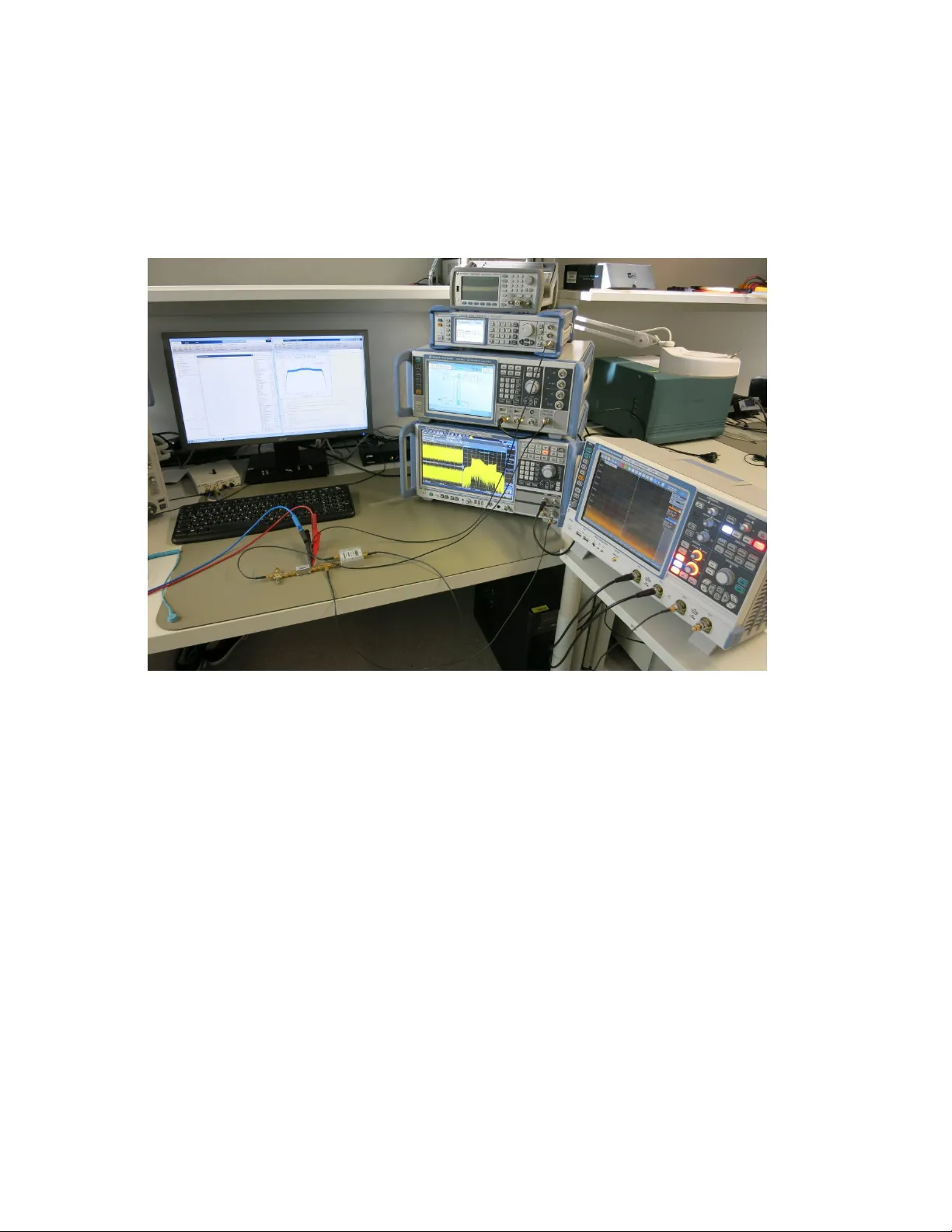
A Rob ust Nonlinear RLS T ype Adaptiv e Filter f or Second-Order -Intermodulation Distortion Cancellation in FDD L TE and 5G Dir ect Con version T ransceiv ers Andreas Gebhard ∗ , Oli ver Lang ‡ , Michael Lunglmayr ‡ , Christian Motz ∗ Ram Sunil Kanumalli † , Christina Auer ∗ , Thomas Paireder ∗ , Matthias W agner ∗ , Harald Pretl § † and Mario Huemer ∗ ∗ Christian Doppler Laboratory for Digitally Assisted RF T ransceiv ers for Future Mobile Communications, Institute of Signal Processing, Johannes K epler Uni versity , Linz, Austria ‡ Institute of Signal Processing, Johannes K epler Uni versity , Linz, Austria † Danube Mobile Communications Engineering GmbH & Co KG, Freist ¨ adter Straße 400, 4040 Linz, Austria § Institute for Integrated Circuits, Johannes K epler Uni versity , Linz, Austria Email: andreas.gebhard@jku.at Abstract T ransceiv ers operating in frequency division duplex experience a transmitter leakage (TxL) signal into the receiver due to the limited duplex er stop-band isolation. This TxL signal in combination with the second-order nonlinearity of the receiv e mixer may lead to a baseband (BB) second-order intermod- ulation distortion (IMD2) with twice the transmit signal bandwidth. In direct conv ersion receiv ers, this nonlinear IMD2 interference may cause a sev ere signal-to-interference-plus-noise ratio degradation of the wanted receiv e signal. This contribution presents a nonlinear W iener model recursiv e-least-squares (RLS) type adapti ve filter for the cancellation of the IMD2 interference in the digital BB. The included channel-select-, and DC-notch filter at the output of the proposed adaptiv e filter ensure that the pro vided IMD2 replica includes the receiver front-end filtering. A second, rob ust v ersion of the nonlinear RLS algorithm is deriv ed which provides numerical stability for highly correlated input signals which arise in e.g. L TE-A intra-band multi-cluster transmission scenarios. The performance of the proposed algorithms is ev aluated by numerical simulations and by measurement data. Index terms — second-order intermodulation, self-interference, adaptive filters, interference can- cellation, L TE-A, 5G, RLS I . I N T RO D U C T I O N Modern radio frequency (RF) transcei vers are enhanced by digital signal processing to mitigate non-idealities in the analog front-end. One of the main reasons of receiv er desensitization in frequency di vision duplex (FDD) transceiv ers is the limited duplex er isolation between the transmitter and the recei ver which is around 50 dB to 55 dB [1,2]. The resulting transmitter leakage (TxL) signal can be identified as the root cause of sev eral receiv er baseband (BB) interferences. Especially in carrier aggregation (CA) recei vers multiple clock sources are needed to cov er the different CA scenarios and band combinations. Due to cross-talk between the recei vers on the chip and device nonlinearities, spurs appear in the receiv er front-end. - - x BB [ n ] y Rx RF ( t ) d Q [ n ] d I [ n ] w I [ n − 1] ˆ y 0 I ˆ y A C,I [ n ] = ˆ y IMD2 BB,I [ n ] e Q [ n ] = = ˆ y Rx BB [ n ] + = { v BB [ n ] } e I [ n ] 1 tap RLS | | 2 LNA P A ¯ h s [ n ] ¯ h s [ n ] ¯ h s [ n ] CSF + DC − 1 CSF + DC − 1 CSF + DC − 1 h TxL RF ( t ) A D A D A D nonlinear IM2RLS Tx leakage f Tx f Tx f Tx f Tx f Rx f Rx 90 ◦ 0 ◦ α Q 2 α I 2 f f 0 f Rx Tx Fig. 1. Block diagram depicting an RF transceiv er operating in FDD mode which experiences a second-order intermodulation distortion in the receiver due to the transmitter leakage signal and the Rx mixer RF-to-LO terminal coupling. A nonlinear RLS-type adaptiv e filters is used to estimate the I-path IMD2 interference. The Q-path IMD2 interference is estimated with a linear 1-tap RLS adaptiv e filter which uses the estimated I-path IMD2 replica as reference input. If such a spur f alls near the actual transmit (Tx) frequency , then the TxL signal is down- con v erted into the Rx BB where it causes a signal-to-interference-plus-noise ratio (SINR) degra- dation of the wanted recei ve signal. The cancellation of this so called modulated spurs with adapti ve filtering is demonstrated in [3,4]. Another prominent interference caused by the TxL signal and the second-order nonlinearity of the recei ver is the second-order intermodulation distortion (IMD2). This second-order nonlinear distortion is caused by e.g. a coupling between the RF- and LO-ports in the I-, and Q-path of the Rx IQ-mixer as indicated in Fig. 1 [5]. An interesting fact of this nonlinear interference is, that one part of the generated second-order intermodulation products alw ays falls around zero-frequency independent of the Tx-to-Rx frequency offset (duplexing distance). In case of direct-con v ersion recei ver architectures, this leads to a degradation of the wanted receiv e signal. The mathematical modeling in [6,7] sho ws that the BB IMD2 interference contains the squared en v elope of the BB equiv alent TxL signal. The resulting BB IMD2 interference has twice the Tx signal bandwidth and contains a DC due to the en velope-squaring. In the receiv er front-end, the overall DC arising from a number of sources is canceled by a mixed-signal cancellation to pre vent the analog-to-digital con verter (ADC) from saturation. In the digital domain, the signal is filtered by a channel-select filter (CSF) to reduce its bandwidth to the Long T erm Ev olution (L TE) signal bandwidth. In the existing literature, the authors of [8]–[10] discussed adaptiv e least-mean-squares (LMS) type IMD2 interference cancellation algorithms for frequency-flat duplex er stop-bands. In [11] a V olterra kernel based least-squares (LS) approach for frequency-selecti ve Tx-Rx responses is proposed. The authors in [7] presented a two-step LS approach for the IMD2 cancellation and considered a static 3rd-order power amplifier (P A) nonlinearity and IQ-imbalance in the transmit mixer . In [12] a Tx CA transceiv er is considered where the transmit signal of both transmitters leaks through a diplexer into one unpaired CA receiv er . The diplex er stop-band is modeled as a first-order finite impulse response (FIR) system which states a nearly frequency-flat response. The authors incorporated a fourth-order nonlinearity without memory into the estimation process, which results in an LS problem with four unkno wn coef ficients. This contribution presents a nonlinear W iener model RLS type adaptiv e filter (IM2RLS) with exponential forgetting factor which is suitable for highly frequency selecti ve duplex er stop- band frequency responses like indicated in Fig. 2. It targets the digital IMD2 cancellation for high performance cellular base stations and mobile phones. The W iener model uses a static nonlinearity at the output of the adaptiv e filter which has the advantage that less coef ficients are needed in the estimation process compared to a V olterra kernel based adapti ve filter [13]. An additional version of the proposed algorithm is presented which enhances the algorithm by a DC-notch filter to cancel the DC in the interference replica. This is needed because direct- con v ersion recei vers employ a DC cancellation to suppress the DC in order to pre vent the ADC from saturation. The DC in the receiv ed signal is time-variant and has many sources like e.g. LO-LO self mixing [5], and therefore must not be related explicitly to the DC which is generated by the IMD2 interference. Consequently , the IMD2 interference related DC is remov ed from the recei ved signal which complicates the IMD2 replica estimation. This DC remov al is considered in [6,11], and neglected in [7]–[9,14]. The deriv ed IM2RLS with DC-notch filter is extended by a regularization (R-IM2RLS) which makes the algorithm applicable for highly correlated BB transmit signals where the autocorre- lation matrix can be close to singular . A high correlation in the transmit signal can be due to ov ersampling which happens e.g. in the case of multi-cluster transmissions (introduced in 3GPP L TE-A Release 11) where only a part of the a vailable resource blocks (RBs) are allocated. The presented IM2RLS algorithm is an extension to the nonlinear LMS type adapti ve filter deriv ed in [6] with improved steady-state cancellation and con ver gence speed. The structure of the presented work is as follows: Section II explains the second-order input intercept point (IIP2) characterization and demonstrates the degradation of the Rx performance due to the IMD2 interference. Section III provides a detailed IMD2 interference model which moti vates the proposed structure of the nonlinear adaptiv e filter . In Section IV, the IM2RLS algorithm is deriv ed and the impact of adding a DC-notch filter to the algorithm is ev aluated. The R-IM2RLS alrorithm is deriv ed in section V which is rob ust against highly correlated input signals as they occur in intra-band multi-cluster transmissions. Finally , in the sections VI and VII, the performance of the R-IM2RLS algorithm is e valuated with simulations and measured data using RF components. I I . P R O B L E M S T A T E M E N T The recei ver IIP2 is characterized by using two cosine signals with the frequencies f 1 and f 2 of equal amplitude and the total power P in,2t at the input of the nonlinear mixer . The resulting total IMD2 po wer generated at DC, f 1 + f 2 and f 2 − f 1 at the output of the mixer can be calculated by P T ot,2t IM2 = 2 P in,2t − IIP2 2t [15], where IIP2 is the two-tone IIP2 value in dBm. Here, half of the total IMD2 po wer falls to DC, and one quarter each to f 1 + f 2 and f 2 − f 1 . T o characterize the IIP2 in a zero-IF recei ver , the frequencies f 1 and f 2 are chosen such that f 2 − f 1 falls within the CSF bandwidth. Thereby the power at f 2 − f 1 is measured and the IIP2 is determined by IIP2 2t = 2 P in,2t − P f 2 − f 1 IM2 − 6 dB. For modulated signals, the BB IMD2 power is modulation dependent and further reduced by the CSF. This is considered by a correction-factor which corrects the IMD2 power calculated by the two-tone formula [16,17]. Although the DC-, and channel-select filtering in the receiv er reduces the IMD2 BB inter- ference power by 6 dB in the two-tone signal case [15], and by about 13.4 dB [6,16,17] in the case of modulated Tx signals, the left-ov er IMD2 interference may lead to a sev ere signal- to-noise ratio (SNR) degradation of the w anted Rx signal in reference sensiti vity cases [18]. Assuming a transmitter power of 23 dBm at the antenna, and an av erage Tx-to-Rx duplexer isolation at the transmit frequency of 50 dB, the TxL signal power at the input of the receiv er is P TxL RF = 23 dBm − 50 dB = − 27 dBm. After amplification with the lo w noise amplifier (LNA) gain which is assumed as 20 dB, the RF TxL signal po wer increases to P TxL RF = − 7 dBm at the input of the nonlinear mixer . The two-tone IIP2 v alue of typical RF mixers is between 50 dBm and 70 dBm [19,20]. Assuming an IIP2 of 60 dBm, the resulting BB IMD2 power with a full allocated L TE10 QPSK modulated transmission and the determined correction factor of CF = 13 . 4 dB is P CSF ,L TE IM2 = 2 P TxL RF − IIP2 − CF = − 87 . 4 dBm [6]. In an L TE10 reference sensitivity case, the wanted signal power at the antenna can be as low as -97 dBm [18]. The thermal noise po wer within 10 MHz bandwidth is -104.5 dBm and the assumed receiv er noise figure (NF) is 4.5 dB which results in a receiv er noise floor at -100 dBm. After amplification with 20 dB LN A gain, the wanted signal power is -77 dBm and the noise floor at -80 dBm corresponding to an Rx SNR of 3 dB. The SNR drops from 3 dB to an SINR of 2.27 dB due to the IMD2 interference assuming an IIP2 of +60 dBm. In case of an reduced IIP2 of 55 dBm / 50 dBm, the SINR drops e ven further to 1 dB / -1.4 dB, respecti vely . Fig. 2 depicts the spectrum of the frequency selecti ve BB equiv alent TxL signal y TxL BB which generates the complex valued IMD2 interference y IMD2 BB by a coupling between the RF-to-LO terminals of the I-, and Q-path mixer . The total receiv ed signal y T ot BB contains the wanted Rx signal y Rx BB which is degraded by the IMD2 interference and the noise. − 8 − 6 − 4 − 2 0 2 4 6 8 − 160 − 140 − 120 − 100 − 80 − 60 − 40 − 20 f [MHz] PSD [dBm/15 kHz] y TxL BB y T ot BB y Rx BB y IMD2 BB Noise Fig. 2. Equi valent BB spectrum of the frequency-selectiv e Tx leakage signal y TxL BB (the corresponding passband signal is located at f Tx ) and the total receiv ed signal y T ot BB after amplification with 20 dB LN A gain. The wanted Rx signal with SNR = 3 dB, and the receiver noise floor after amplification with 20 dB LNA gain are at -77 dBm and -80 dBm b = -108.2 dBm/15 kHz respectiv ely . The total recei ved signal contains the DC-, and channel-select filtered IMD2 interference with P Tx = 23 dBm at an assumed IIP2 of 50 dBm. I I I . S Y S T E M M O D E L A. IMD2 Interfer ence Model Based on the block diagram in Fig. 1 depicting an RF transceiv er operating in FDD mode, a detailed IMD2 interference model is deriv ed. The used mathematical operators ( . ) ∗ , ( . ) T , ( . ) H , and ∗ denote the complex conjugate, transpose, Hermitian transpose, and con volution, respecti vely . The complex BB transmit signal x BB ( t ) = x I ( t ) + j x Q ( t ) is up-con verted to the passband and amplified by the linearly assumed P A with gain A P A resulting in the RF transmit signal x RF ( t ) = A P A < x BB ( t ) e j 2 πf Tx t . (1) This signal leaks through the duplexer RF stop-band impulse response h TxL RF ( t ) = 2 < h TxL BB ( t ) e j 2 πf Tx t , (2) which is modeled by the BB equi v alent duplex er impulse response h TxL BB ( t ) into the receiv er , thereby creating the TxL signal y TxL RF ( t ) = x RF ( t ) ∗ h TxL RF ( t ) = A P A < x BB ( t ) ∗ h TxL BB ( t ) e j 2 πf Tx t . (3) The receiv ed signal at the output of the LNA with gain A LN A y T ot RF ,LNA ( t ) = A LN A y TxL RF ( t ) + y Rx RF ( t ) + v RF ( t ) , (4) is composed by the amplified TxL signal, the wanted Rx signal y Rx RF ( t ) and the noise signal v RF ( t ) . The output signal of the I-, and Q-path mixer is combined into the complex valued signal y T ot RF ,mixer ( t ) (5). It contains the wanted signal which is down-con verted with the linear gain α 1 = α I 1 + j α Q 1 , and the second order interference with the mixer RF-to-LO terminal coupling coef ficient α 2 = α I 2 + j α Q 2 . y T ot RF ,mixer ( t ) = y T ot RF ,LNA ( t ) α I 1 cos (2 π f Rx t ) + y T ot RF ,LNA ( t ) α I 2 y T ot RF ,LNA ( t ) − j y T ot RF ,LNA ( t ) α Q 1 sin (2 π f Rx t ) + j y T ot RF ,LNA ( t ) h α Q 2 y T ot RF ,LNA ( t ) i = y T ot RF ,LNA ( t ) α 1 e − j 2 πf Rx t + α 2 y T ot RF ,LNA ( t ) 2 (5) Assuming a direct con version receiv er , and using the identity < { η e j κ } = 1 2 ( η e j κ + η ∗ e − j κ ) , the total mix er output signal by neglecting the signal content which falls outside the BB bandwidth becomes y T ot RF ,mixer ( t ) = α 1 A LN A 2 y Rx BB ( t ) + α 1 A LN A 2 v BB ( t ) + α 2 2 · A LN A A P A x BB ( t ) ∗ h TxL BB ( t ) 2 + 1 2 y Rx BB ( t ) 2 + < y Rx BB ( t ) v ∗ BB ( t ) + 1 2 | v BB ( t ) | 2 . (6) As | α 2 | << 1 , the three last terms in (6) may be neglected [6,7]. The total received discrete-time BB signal including the DC-cancellation and channel-select filtering becomes y T ot BB [ n ] = α 1 A LN A 2 y Rx BB [ n ] ∗ ¯ h s [ n ] + α 1 A LN A 2 v BB [ n ] ∗ ¯ h s [ n ] + α 2 2 A LN A A P A x BB [ n ] ∗ h TxL BB [ n ] 2 ∗ ¯ h s [ n ] | {z } y IMD2 BB [ n ] , (7) where the DC-, and CSF are combined in the impulse response ¯ h s [ n ] = h DC [ n ] ∗ h s [ n ] . Here, h TxL BB [ n ] = T s h TxL BB ( t ) t = nT s is the impulse in variant [21,22], scaled and sampled version of the continuous-time BB duplex er impulse response h TxL BB ( t ) . B. Interfer ence Replica Model For the adapti ve filter de velopment to cancel the IMD2 interference in the digital BB, the interference model (7) is re written to the form y T ot BB [ n ] = α I 2 2 A LN A A P A x BB [ n ] ∗ h TxL BB [ n ] 2 ∗ ¯ h s [ n ] | {z } y IMD2,I BB [ n ] + j α Q 2 2 A LN A A P A x BB [ n ] ∗ h TxL BB [ n ] 2 ∗ ¯ h s [ n ] | {z } y IMD2,Q BB [ n ] + v 0 BB [ n ] (8) where the complex valued wanted signal and the noise signal are combined in v 0 BB [ n ] . Assuming α I 2 > 0 , and approximating the duplexer impulse response h TxL BB [ n ] by the FIR impulse response vector h TxL BB of length N w , we can rewrite the model (8) further to y T ot BB [ n ] = x T [ n ] h I 2 ∗ ¯ h s [ n ] + j x T [ n ] h Q 2 ∗ ¯ h s [ n ] + v 0 BB [ n ] = y IMD2,I BB [ n ] + j y IMD2,I BB [ n ] + v 0 BB [ n ] , (9) where h I and h Q are incorporating h TxL BB and all scalar scaling factors in the I-, and Q-path respecti vely . The used vector x [ n ] is the complex valued tapped delay-line input signal vector x [ n ] = [ x BB [ n ] , x BB [ n − 1] , . . . , x BB [ n − N w + 1]] T , and the real v alued scaling factor sho ws that the Q-path IMD2 interference may be modeled as a scaled version of the I-path interference. Moti vated by the model (9) we propose the I-path IMD2 interference replica model ˆ y A C,I [ n ] = x T [ n ] w I [ n ] 2 ∗ ¯ h s [ n ] , (10) using the adaptiv e filter coefficient vector w I [ n ] . The index A C indicates the DC cancellation in the IMD2 replica generation. The replica model comprises an adaptive W iener model FIR filter where the output signal is DC-, and channel-select filtered. The Q-path IMD2 interference is generated by estimating the scaling parameter by a linear single-tap RLS algorithm which uses the estimated I-path IMD2 interference as reference input. This model is used to deriv e the adapti ve filter structure shown in Fig. 1 to cancel the IMD2 interference in the digital BB. For the case if α I 2 < 0 , the sign of the desired signal in the I-path d I and the replica signal of the adapti ve filter need to be changed. I V . N O N L I N E A R R E C U R S I V E L E A S T - S Q U A R E S A L G O R I T H M In this section, a nonlinear W iener model RLS type adaptiv e filter to estimate the channel- select filtered I-path IMD2 interference is dev eloped. In a first step the IM2RLS algorithm without DC-notch filter , which implies that the recei ved signal contains the DC, is de veloped. Therefore, the replica model (10) without DC cancellation ˆ y I [ n ] = x T [ n ] w I [ n ] 2 ∗ h s [ n ] = x T [ n ] w I [ n ] x H [ n ] w ∗ I [ n ] ∗ h s [ n ] (11) is used. The LS cost function up to the time index n with the exponential forgetting f actor 0 << λ ≤ 1 is J LS [ n ] = n X i =0 λ n − i d I [ i ] − x T [ i ] w I [ n ] x H [ i ] w ∗ I [ n ] ∗ h s [ i ] 2 . (12) This cost function is visualized in Fig. 3 for an example impulse response h I = [1 , 0 . 5] T and λ = 1 where the estimated coefficients w I,0 and w I,1 are constrained to be real v alued. T wo equi valent global minimum points and a local maximum at the origin w I = 0 can be observed. The two solutions w I,1 = [1 , 0 . 5] T , and w I,2 = [ − 1 , − 0 . 5] T minimize the cost function which can be explained with the absolute-squaring nature of the IMD2 interference. Both solutions lead to the same IMD2 replica signal. Assuming real valued CSF impulse response coefficients h s [ n ] , − 1 − 0 . 5 0 0 . 5 1 − 1 − 0 . 5 0 0 . 5 1 0 2 4 6 8 · 10 4 w I , 0 w I , 1 J LS ( w I , 0 , w I , 1 ) Fig. 3. Shape of the cost function (12) for white Gaussian input signals with λ = 1 and for the real valued coefficient vector h I = [1 , 0 . 5] T when the desired signal d I [ n ] and the IMD2 replica are containing the DC. At the origin w I = 0 , a local maximum can be observed. and observing that d I [ i ] is the desired signal in the I-path, and therefore real valued, the gradient of the cost function (12) may be deriv ed. The gradient of the cost function with respect to the conjugate coefficient vector w ∗ I using the W irtinger calculus [23]–[25] becomes ∇ w ∗ I J LS = ∂ J LS [ n ] ∂ w ∗ I [ n ] T = n X i =0 λ n − i − 2 d I [ i ] x T [ i ] w I [ n ] x ∗ [ i ] ∗ h s [ i ] +2 x T [ i ] w I [ n ] x ∗ [ i ] ∗ h s [ i ] · x H [ i ] w ∗ I [ n ] x T [ i ] ∗ h s [ i ] w I [ n ] . (13) By setting the gradient to zero, the W iener Filter equation is obtained by ˜ R ( w I [ n ]) w I [ n ] = ˜ r ( w I [ n ]) , (14) where it can be observed that the autocorrelation matrix ˜ R and the cross-correlation vector ˜ r are functions of the unknown coefficient vector w I [ n ] . In a slowly varying or nearly stationary system en vironment it can be assumed that x T [ i ] w [ n ] ≈ x T [ i ] w [ i − 1] when the index i is close to n [26,27]. If the index i << n , the approximation introduces an error which is howe ver attenuated by the forgetting factor . Defining the new cost function J 0 LS [ n ] = n X i =0 λ n − i d I [ i ] − x T [ i ] w I [ i − 1] x H [ i ] w ∗ I [ n ] ∗ h s [ i ] 2 = n X i =0 λ n − i d I [ i ] − z T [ i ] w ∗ I [ n ] ∗ h s [ i ] 2 = n X i =0 λ n − i | e I [ i ] | 2 (15) and introducing the new input vector z [ i ] = x T [ i ] w I [ i − 1] x ∗ [ i ] , we can overcome this limitation. Follo wing the traditional RLS deri v ation [28], the IM2RLS algorithm to estimate the I-path IMD2 interference in the digital BB becomes (16)-(20): ˆ y I [ n ] = z T [ n ] w ∗ I [ n − 1] ∗ h s [ n ] (16) e I [ n ] = d I [ n ] − ˆ y I [ n ] (17) k [ n ] = P [ n − 1] z f [ n ] λ + z H f [ n ] P [ n − 1] z f [ n ] (18) P [ n ] = 1 λ P [ n − 1] − k [ n ] z H f [ n ] P [ n − 1] (19) w I [ n ] = w I [ n − 1] + e I [ n ] k [ n ] (20) T o a void the channel-select filtering of each element in the v ector z f [ n ] = z [ n ] ∗ h s [ n ] which is mainly necessary to align the signals due to the CSF group delay , we introduce the signals x f [ n ] = x [ n ] ∗ h s [ n ] and y 0 I [ n ] = x T [ n ] w I [ n − 1] . Using the delay line vector x f [ n ] = [ x f [ n ] , x f [ n − 1] , . . . , x f [ n − M + 1]] T , the vector z f [ n ] may be approximated by z f [ n ] ≈ ( y 0 I [ n ] ∗ h s [ n ]) x ∗ f [ n ] . W ith this formulation, a fractional and non-constant group delay of the CSF may be incorporated. In case if the group delay τ g is constant, and an integer multiple of the sampling time (as e.g. in linear phase FIR filters), the CSF may be approximated by delaying the signal by z f [ n ] ≈ x T [ n − τ g ] w I [ n − 1 − τ g ] x ∗ [ n − τ g ] . In both approximations, the band-limiting ef fect of the CSF on z f [ n ] is ignored. Howe ver , this may be tolerated because due to the en v elope-squaring operation in (11) which doubles the signal bandwidth, anyho w an oversampling factor (OSF) of 2 is mandatory to a v oid aliasing. Due to the fact, that the I-, and Q-path IMD2 interference dif fer only by a real v alued scaling factor as deriv ed in (8), the estimated I-path IMD2 replica may be used as a reference to estimate the Q-path IMD2 replica. This may be done by a linear 1-tap RLS algorithm which uses the estimated I-path replica as reference input signal to estimate the Q-path IMD2 replica. In this case, the 1-tap RLS estimates also a possible sign dif ference between the I-, and Q-path IMD2 interference. Consequently , only the sign of α I 2 has to be detected during calibration of the recei ver which may be done by correlation. The replica signal generation (16) is channel-select filtered which reduces the bandwidth of the replica signal to the bandwidth of the received L TE signal. A. Second-Or der Condition The complex Hessian [24,29] of the cost function (12) at the coef ficient v alue w I = 0 becomes H I = ∂ ∂ w I ∂ J LS ∂ w ∗ I T | w I = 0 = n X i =0 λ n − i − 2 d I [ i ] x ∗ [ i ] x T [ i ] ∗ h s [ i ] . (21) If the desired signal d I [ n ] contains the DC (when the receiv er has no DC filtering), then E { d I [ n ] } ≥ 0 and the Hessian matrix becomes neg ativ e semi-definite like depicted with the local maximum in Fig. 3. The usual choice of the zero-vector as initialization of w I [ − 1] results in a zero-gain vector k [ n ] for all n . This is reasoned in the cost function (12) depicted in Fig. 3 which has a local maximum at w I = 0 and therefore a v anishing gradient. Consequently , the algorithm is initialized with w I [ − 1] 6 = 0 and the parameters 0 << λ ≤ 1 , and P [ − 1] = ν I with ν > 0 . B. DC Cancellation T o employ an IMD2 interference replica without DC, the replica signal (16) is filtered by the DC-notch filter (23). The ne w error signal e A C,I [ n ] = d A C,I [ n ] − ˆ y A C,I [ n ] with the DC-filtered signals is used in the update equation (27). Here, the introduced index AC indicates the DC filtered signals. The IM2RLS algorithm with DC-suppression can be summarized as (22)-(27): ˆ y I [ n ] = z T [ n ] w ∗ I [ n − 1] ∗ h s [ n ] (22) ˆ y A C,I [ n ] = a ˆ y A C,I [ n − 1] + ˆ y I [ n ] − ˆ y I [ n − 1] . (23) e A C,I [ n ] = d A C,I [ n ] − ˆ y A C,I [ n ] (24) k [ n ] = P [ n − 1] z f [ n ] λ + z H f [ n ] P [ n − 1] z f [ n ] (25) P [ n ] = 1 λ P [ n − 1] − k [ n ] z H f [ n ] P [ n − 1] (26) w I [ n ] = w I [ n − 1] + e A C,I [ n ] k [ n ] (27) The parameter 0 << a < 1 in (23) determines the sharpness of the DC-notch filter and is chosen as a = 0 . 998 . In case of DC filtering in the main receiv er E { d I [ n ] } = 0 , and the Hessian matrix (21) at w I = 0 is not positiv e semi-definite anymore. In this case, the local maximum becomes a saddle-point like depicted in Fig. 4. Using N CSF as the number of coef ficients of the CSF impulse response, the computational complexity of the IM2RLS with DC-notch filter is 13 N 2 w + 5 N CSF + 20 N w + 1 real multiplications and 2 N w real divisions per iteration. C. Multiple Solutions of the IM2RLS Algorithm In the cost function shapes depicted in Fig. 3 and Fig. 4, the estimated impulse response coef ficients w 0 and w 1 (omitting the index I for the I-path) are constrained to be real valued. It can be observed that the two solutions w 0 = [1 , 0 . 5] T , and w 1 = [ − 1 , − 0 . 5] T minimize the cost function. The existence of multiple solutions can be explained by the absolute-squaring nature of the IMD2 interference. − 1 − 0 . 5 0 0 . 5 1 − 1 − 0 . 5 0 0 . 5 1 0 2 4 6 8 · 10 4 w I , 0 w I , 1 J LS ( w I , 0 , w I , 1 ) Fig. 4. Shape of the cost function (12) for white Gaussian input signals with λ = 1 and for the two real valued coef ficients h = [1 , 0 . 5] T . The local maximum at w I = 0 (with DC) changed to a saddle-point because the DC filtering is applied. If the coefficients are allowed to be complex valued, all coef ficient pairs { w 0 , w 1 } con ver ge to w end 0 = | h 0 | and w end 1 = | h 1 | . This scenario is visualized in Fig. 5 where the con vergence of the coef ficients with the ten different initializations w i [ − 1] = [1 e − 3 , 0] T exp ( j 2 π / 10 i ) for i = 0 ... 9 is depicted. Furthermore, each of the estimated coefficient vectors w end i = w end 0 ,i , w end 1 ,i T after con ver gence reach the group delay of the real system impulse response h . D. P erformance of the IM2RLS with DC Suppr ession In this section, the performance of the IM2RLS w/o and w/ DC cancellation is compared. In the first case, the recei ver and the IMD2 replica generation of the IM2RLS do not use a DC cancellation. In this hypothetical example it is assumed that the IMD2 interference is the only DC source. In the second case, the receiv er uses a DC suppression, and the IM2RLS the DC-notch filter . Both cases are compared within an FDD scenario with full allocated L TE signals using 10 MHz bandwidth, QPSK modulation, short cyclic prefix, and an OSF of 2. The frequency-selecti v e duplex er stop-band impulse response shown in Fig. 6 is used in (7) for the IMD2 interference generation. It is modeled with an FIR system which has 15 complex v alued coef ficients (on the nativ e L TE10 sampling rate of 15.36 MHz) and a mean Tx-to-Rx isolation of 50 dB [1]. The resulting TxL signal has a strong frequency-selectivity like indicated in Fig. 2. The wanted Rx signal power is at reference sensitivity lev el P Rx = − 97 dBm and the thermal − 1 − 0 . 5 0 0 . 5 1 − 1 − 0 . 5 0 0 . 5 1 < { w 0 } , < { w 1 } = { w 0 } , = { w 1 } h 0 h 1 | h 0 | w 0 ,i [ n ] traj. | h 1 | w 1 ,i [ n ] traj. w end 0 ,i w end 1 ,i Fig. 5. Ill ustration of the initialization-dependent multiple solutions where the true coefficient values are h = [1 , 0 . 5] T . The initial coefficient w 0 [ − 1] is initialized in a 10-point grid around a circle with radius 1 e − 3 . The initial v alue of h 1 [ − 1] is always zero. W ith each initialization, the coef ficients con verge to the correct absolute v alue. All ten resulting estimated impulse response vectors w end i maintain the same group delay as h . noise floor is -104.5 dBm within 10 MHz bandwidth. The receiv er NF is 4.5 dB which results in an recei ver noise floor of -100 dBm. The LNA gain is 20 dB, and the two-tone mix er IIP2 is 50 dBm. This results in an desensitization of the wanted Rx signal from an SNR = 3 dB to an SINR of -1.4 dB at P Tx = 23 dBm. The I-path IMD2 interference is estimated by the IM2RLS using 15 taps, running at the sampling frequency of 30.72 MHz (OSF = 2). This means, the adapti ve filter has less taps than the duplex er stop-band impulse response which has 30 complex v alued coef ficients at OSF = 2. The Q-path IMD2 replica is estimated by a linear 1-tap RLS (running at 30.72 MHz sampling rate) which uses the I-path IMD2 replica as reference input. The IM2RLS algorithm uses the forgetting-f actor λ = 0 . 9999 and P [ − 1] = 100 I as suggested in [30]. The 1-tap RLS in the Q-path uses the same forgetting factor and the initial coeffi- cient p [ − 1] = 1 e 7 . The coefficient vector of the I-path IM2RLS algorithm is initialized with w I [ − 1] = [1 e − 6 , 0 , 0 , ..., 0] T , and the 1-tap RLS with zero. Fig. 7. sho ws the steady state SINR improv ement at dif ferent transmit po wer le vels for an IIP2 of +50 dBm. It can be observ ed, that in both cases (w/o and w/ DC cancellation) the SINR is improv ed nearly up to the Rx SNR of 3 dB. The conv ergence beha vior at the transmit po wer of 23 dBm is depicted in Fig. 8. For the 0 2 4 6 8 10 12 14 − 3 − 2 − 1 0 1 2 3 · 10 − 3 n < h TxL BB [ n ] , = h TxL BB [ n ] < h TxL BB [ n ] = h TxL BB [ n ] Fig. 6. Real and imaginary part of the 15-tap complex valued duplexer impulse response. 9 12 15 18 21 23 − 2 − 1 0 1 2 3 SINR improv ement Rx SNR = 3 dB Tx Power [dBm] Rx SINR [dB] w/o cancellation, IIP2=50dBm Proposed IM2RLS w/o DC-notch filter Proposed IM2RLS w/ DC-notch filter Fig. 7. Improvement of the Rx SINR with the proposed IMD2 cancellation algorithms w/o and w/ using the DC-notch filter at different transmitter power le vels. The mixer IIP2 is 50 dBm and the wanted signal at the antenna has a power of P Rx = -97 dBm and a SNR of 3 dB. hypothetical case that the recei ver and the IM2RLS are using no DC suppression, the IM2RLS con v erges faster than with DC suppression. This is reasoned in the additional DC-IMD2 po wer which supports the algorithm to con verge f aster . The IIP2 improve ment by the digital cancellation T ABLE I I I P 2 I M PR OV E M EN T B Y D I G I T A L C A N C E LL ATI O N IM2RLS Algorithm P CSF IMD2 before P CSF IMD2 after IIP2 after canc. w/o DC cancellation -77.5 dBm -95.8 dBm 68.4 dBm w/ DC cancellation -77.5 dBm -94.5 dBm 67 dBm is summarized in T able I and may be calculated for the IM2RLS with DC-notch filter via IIP2 after canc. = 2 P TxL RF − P CSF ,L TE IM2, after canc. − 13 . 4 dB = 2 · (23 dBm − 50 dB + 20 dB ) + 94 . 5 dBm − 13 . 4 dB = 67 dBm . (28) The IIP2 is improv ed from +50 dBm to 68.4 dBm and 67 dBm by the digital cancellation with the IM2RLS w/o and w/ DC suppression, respectiv ely . The correction factor of 13.4 dB corrects the IMD2 po wer calculated with the 2-tone formula, to the channel-select, and DC- filtered in-band IMD2 power for the L TE10 full allocation case [6]. For the calculation of the IIP2 improv ement, the IMD2 power without DC is used in both cases. The deri ved IM2RLS algorithm with included DC-notch filter shows an excellent cancellation performance for a full allocated L TE10 transmit signal. Ho we ver , for small bandwidth allocations like e.g. used in multi-cluster transmissions, the RLS-type algorithm suf fers from numerical instability due to the badly-conditioned autocorrelation matrix ˜ R . T o overcome this limitation, the regularized IM2RLS (R-IM2RLS) is deriv ed in the next section. V . T I K H O N OV R E G U L A R I Z A T I O N O F T H E N O N L I N E A R R L S T o reduce the spectral out-of-band (OOB) emission of the L TE signals, not all av ailable subcarriers are allocated. A portion of the subcarriers at the band-edges (guard-band) are forced to zero which introduces correlation in the transmit BB samples. E.g. in a 10 MHz L TE signal a maximum of 600 out of 10 24 subcarriers may be occupied by data [31]. This correlation in the Tx BB signal x BB [ n ] leads to an badly-conditioned autocorrelation matrix R = E x BB [ n ] x H BB [ n ] and respectiv ely ˜ R = E z f [ n ] z H f [ n ] . Algorithms which need the estimation of the autocorre- lation matrix or its in verse P = R − 1 to estimate the system coefficients either iterati vely or in batch-mode, are sensitiv e to the condition number of R and may suffer from numerical instability if R is badly-conditioned. Because of this reason, a regularized version of the IM2RLS algorithm (R-IM2RLS) is deri ved in this section. 0 2 4 6 8 10 12 14 16 18 20 − 30 − 20 − 10 0 L TE10 slots with OSF=2 NMSE [dB] Proposed IM2RLS w/o DC-notch filter Proposed IM2RLS w/ DC-notch filter Fig. 8. Con vergence of the IM2RLS w/o and w/ DC-notch filter for an L TE transmit signal with 10 MHz bandwidth, OSF of 2 and P Tx = 23 dBm. The wanted Rx signal power at the antenna input is P Rx = -97 dBm and the Rx SNR = 3 dB. The mixer IIP2 is +50 dBm which corresponds to an Rx SNR desense of 4.4 dB. A common method to overcome the problem of badly-conditioned autocorrelation matrices is regularization [28]. Adding a positi ve definite matrix to the estimated auto-correlation matrix in each iteration of the RLS algorithm guarantees that the re gularized autocorrelation matrix ˜ R 0 stays positiv e definite and maintains therefore the necessary condition for con ver gence and existence of P = ˜ R 0− 1 [32]. This method is commonly known as T ikhonov-re gularization where a matrix L is used for the regularization [33]. By including a regularization term in the cost function (15), the ne w cost function J 0 R [ n ] = n X i =0 λ n − i | e I [ i ] | 2 + σ k Lw I [ n ] k 2 2 = n X i =0 λ n − i | e I [ i ] | 2 + σ w T I [ n ] L T Lw ∗ I [ n ] (29) is defined where e I [ i ] = d I [ i ] − z T [ i ] w ∗ I [ n ] ∗ h s [ i ] . The regularization parameter σ ≥ 0 is used to adjust the regularization amount and the real v alued matrix L is typically chosen as L = I (standard T ikhonov regularization), L = upperbidiag (1 , − 1) (first order deriv ati ve), or L = − 2 1 1 − 2 1 1 − 2 1 . . . . . . . . . 1 − 2 (30) (second order deri vati ve) [33]. Using the Wirtinger calculus [23] to obtain the gradient of the cost function (29), and setting the gradient to zero results in " n X i =0 λ n − i z f [ i ] z H f [ i ] + σ L T L # | {z } ˜ R 0 [ n ] w I [ n ] = n X i =0 λ n − i d I [ i ] z f [ i ] | {z } ˜ r [ n ] . (31) Reformulating the abov e equation leads to w I [ n ] = ˜ R 0− 1 [ n ] ˜ r [ n ] = P [ n ] ˜ r [ n ] which is solved recursi vely using the RLS algorithm. By expressing the cross-correlation vector ˜ r [ n ] by its pre vious estimate ˜ r [ n − 1] , a recursi ve estimation of the form ˜ r [ n ] = λ ˜ r [ n − 1] + d I [ n ] z f [ n ] (32) may be formulated. Similarly , a recursi ve estimation of the regularized autocorrelation matrix is obtained by ˜ R 0 [ n ] = λ n − 1 X i =0 λ n − i − 1 z f [ i ] z H f [ i ] + σ L T L + z f [ n ] z H f [ n ] + σ L T L = λ ˜ R 0 [ n − 1] + σ L T L + z f [ n ] z H f [ n ] . (33) Substituting Ω [ n ] − 1 = λ ˜ R 0 [ n − 1] + σ L T L into (33), the matrix P [ n ] = ˜ R 0− 1 [ n ] becomes P [ n ] = Ω [ n ] − 1 + z f [ n ] z H f [ n ] − 1 . (34) After applying the matrix in version lemma ( A + BCD ) − 1 = A − 1 − A − 1 B C − 1 + D A − 1 B − 1 D A − 1 (35) to av oid the matrix inv ersion, (34) may be formulated as P [ n ] = Ω [ n ] − k [ n ] z H f [ n ] Ω [ n ] (36) using the gain vector k [ n ] = Ω [ n ] z f [ n ] 1 + z H f [ n ] Ω [ n ] z f [ n ] . (37) For the in version Ω [ n ] = λ P − 1 [ n − 1] + σ L T L − 1 , (38) again the matrix in version lemma is applyied which yields Ω [ n ] = 1 λ ( P [ n − 1] − Σ [ n ] LP [ n − 1]) (39) where the substitution Σ [ n ] = σ P [ n − 1] L T λ I + σ LP [ n − 1] L T − 1 (40) is used. After rearranging (40), the expression Σ [ n ] = σ λ ( P [ n − 1] − Σ [ n ] LP [ n − 1]) L T = σ Ω [ n ] L T (41) is obtained. Unfortunately , the calculation of Σ [ n ] in (40) and therefore Ω [ n ] still includes a matrix in version after applying the matrix in version lemma. Howe ver , by decomposing the matrix L T L in (38) into a sum of V dyads [34] Ω [ n ] = " λ P − 1 [ n − 1] + σ V X k =1 p k, 1 p T k, 2 # − 1 , (42) applying the matrix in version lemma results in the recursiv e calculation of (42) via Ω k [ n ] = Ω k − 1 [ n ] − Ω k − 1 [ n ] p k, 1 1 σ + p T k, 2 Ω k − 1 [ n ] p k, 1 p T k, 2 Ω k − 1 [ n ] (43) for k = 1 . . . V in each iteration n and Ω 0 [ n ] = 1 λ P [ n − 1] . Reformulating (37) yields k [ n ] = P [ n ] z f [ n ] . (44) The recursiv e update of the coefficient v ector w I [ n ] is obtained by inserting (36), (32), (44), (39) and (41) into w I [ n ] = P [ n ] ˜ r [ n ] . The final nonlinear R-IM2RLS algorithm to estimate the I-path IMD2 interference is summarized by (45)-(51): ˆ y I [ n ] = z T [ n ] w ∗ I [ n − 1] ∗ h s [ n ] (45) e I [ n ] = d I [ n ] − ˆ y I [ n ] (46) Ω k [ n ] = Ω k − 1 [ n ] − Ω k − 1 [ n ] p k, 1 1 σ + p T k, 2 Ω k − 1 [ n ] p k, 1 p T k, 2 Ω k − 1 [ n ] (47) k [ n ] = Ω V [ n ] z f [ n ] 1 + z H f [ n ] Ω V [ n ] z f [ n ] . (48) P [ n ] = Ω V [ n ] − k [ n ] z H f [ n ] Ω V [ n ] (49) Σ [ n ] = σ Ω V [ n ] L T (50) w I [ n ] = I − I − k [ n ] z H f [ n ] Σ [ n ] L w I [ n − 1] + k [ n ] e I [ n ] (51) The proposed algorithm is initialized with w I [ − 1] 6 = 0 , 0 << λ ≤ 1 and P [ − 1] = ν I with ν > 0 . When the DC suppression is used, then the R-IM2RLS update equations become (52)-(59): ˆ y I [ n ] = z T [ n ] w ∗ I [ n − 1] ∗ h s [ n ] (52) ˆ y A C,I [ n ] = 0 . 998 ˆ y A C,I [ n − 1] + ˆ y I [ n ] − ˆ y I [ n − 1] (53) e A C,I [ n ] = d A C,I [ n ] − ˆ y A C,I [ n ] (54) Ω k [ n ] = Ω k − 1 [ n ] − Ω k − 1 [ n ] p k, 1 1 σ + p T k, 2 Ω k − 1 [ n ] p k, 1 p T k, 2 Ω k − 1 [ n ] (55) k [ n ] = Ω V [ n ] z f [ n ] 1 + z H f [ n ] Ω V [ n ] z f [ n ] . (56) P [ n ] = Ω V [ n ] − k [ n ] z H f [ n ] Ω V [ n ] (57) Σ [ n ] = σ Ω V [ n ] L T (58) w I [ n ] = I − I − k [ n ] z H f [ n ] Σ [ n ] L w I [ n − 1] + k [ n ] e A C,I [ n ] (59) The DC-notch filter (53) is used to remove the DC from the IMD2 replica (52). The complexity of the R-IM2RLS with DC-notch filter and L = σ I is 8 N 3 w + 21 N 2 w + 5 N CSF + 18 N w + 1 real multiplications and 2 N 2 w + 2 N w real divisions per iteration. V I . S I M U L A T I O N E N V I R O N M E N T The performance of the R-IM2RLS algorithm with the three abov e mentioned regularization matrices L is ev aluated with an FDD scenario using an L TE10 multi-cluster intra-band Tx signal which has a native sampling frequency of f s = 15 . 36 MHz, QPSK modulation and short cyclic prefix. The IMD2 interference in the I-path is estimated by the R-IM2RLS, while the Q-path IMD2 is estimated by a linear 1-tap RLS which uses the I-path IMD2 replica as reference input. The resulting multi-cluster TxL signal has a strong frequency-selecti vity like indicated in Fig. 9. The R-IM2RLS in the I-path has 15 taps and runs on the higher sampling rate of 30.72 MHz due to the OSF of 2. This means, the adaptive filter has less taps than the impulse response which is estimated. The linear 1-tap Q-path RLS runs also on the sampling rate of 30.72 MHz. The recei ved signal d [ n ] is DC filtered and the proposed algorithm is using the DC-notch filter to suppress the DC of the IMD2 replica signal. The wanted Rx signal has a po wer of P Rx = -97 dBm at the antenna with an SNR of 3 dB. The assumed Rx mixer IIP2 is +60 dBm which corresponds to an Rx SNR desense of 1 dB for the specific intra-band multi-cluster transmit signal at 23 dBm po wer lev el. The thermal noise floor of the receiv er is assumed at -104.5 dBm per 10 MHz and the recei ver NF is 4.5 dB. The resulting receiv er noise floor and Rx power with 20 dB LN A gain is at -80 dBm b = -108.2 dBm/15 kHz and -77 dBm respectively . The spectrum of the signals at P Tx = 23 dBm is depicted in Fig. 9. It can be observed, that the resulting IMD2 interference y IMD2 BB is mostly below the recei ver noise floor but still leads to an SNR degradation of 1 dB. The depicted interference replica is estimated by the R-IM2RLS with the regularization L = 3 e − 7 I . The multi-cluster L TE10 Tx signal uses 21/50 RBs (252 subcarriers from 1024), which means hat 3.78 MHz of the av ailable 9.015 MHz are allocated. W ith an OSF of 2 this corresponds to an allocated bandwidth-to-sampling-rate ratio of 3.78/30.72 = 0.12 which introduces a high correlation in the transmit BB samples. The resulting condition number cond ( ˜ R ) of the 15 × 15 dimensional autocorrelation matrix ˜ R = E z f z H f is in the order of 10 7 which results in a bad conditioned estimation, and may lead to numerical problems. The regularization of the R- IM2RLS improves numerical estimation of the matrix P [ n ] by lowering the condition number of the regularized matrix ˜ R 0 . A. IMD2 Self-Interfer ence of a Multi-Cluster Tx Signal For the estimation of the resulting IMD2 interference bandwidth, the bandwidth between the minimum and maximum allocated subcarrier in the multi-cluster Tx signal is of interest. In the − 8 − 6 − 4 − 2 0 2 4 6 8 − 200 − 180 − 160 − 140 − 120 − 100 − 80 − 60 − 40 − 20 f [MHz] PSD [dBm/15 kHz] y TxL BB y T ot BB y Rx BB y IMD2 BB ˆ y IMD2 BB Noise Fig. 9. Equi valent BB spectrum of the frequency-selectiv e Tx leakage signal y TxL BB (the corresponding passband signal is located at f Tx ) and the total receiv ed signal y T ot BB after amplification with 20 dB LNA gain. The wanted Rx signal with SNR = 3 dB, and the receiver noise floor after amplification with 20 dB LNA gain are at -77 dBm and -80 dBm b = -108.2 dBm/15 kHz respectively . The total recei ved signal contains the DC-, and channel-select filtered IMD2 interference at P Tx = 23 dBm and the IIP2 is 60 dBm. used clustered L TE10 transmit signal the allocated RBs are { 9 − 11 , 29 − 46 } with a numbering from left to right and the total number of 50 RBs. For the IMD2 bandwidth estimation the resulting bandwidth between the lo west allocated subcarrier (RB 9) and the upper edge (RB 46) of the allocated RBs is (3 + 17 + 18) · 12 · 15 kHz = 6 . 84 MHz. Each RB has 12 subcarriers and 15 kHz subcarrier spacing. The resulting IMD2 interference bandwidth is 2 × 6 . 84 MHz = 13 . 68 MHz which means that a small portion of the IMD2 interference is suppressed by the CSF. The full IMD2 interference including the DC, the IMD2 interference after the CSF and DC-remov al, and the estimated IMD2 replica are visualized in Fig. 10. It can be observed, that the R-IM2RLS is able to estimate the IMD2 interference down to 20 dB below the recei ver noise floor . B. Numerical Simulation Results In the follo wing simulation results, the IMD2 self-interference cancellation performance in case of an intra-band multi-cluster Tx signal, using the R-IM2RLS algorithm (52)-(59) using the DC-notch filter with dif ferent regularization matrices is e valuated. The forgetting factor of the R-IM2RLS is chosen as λ = 0 . 9999 , P [ − 1] = 100 I , and the regularization constant σ = 3 e − 7 . The 1-tap RLS in the Q-path uses the same forgetting factor but the initial coefficient p [ − 1] = − 8 − 6 − 4 − 2 0 2 4 6 8 − 160 − 140 − 120 − 100 f [MHz] PSD [dBm/15 kHz] full IMD2 with DC y IMD2 BB ˆ y IMD2 BB Noise Fig. 10. Generated IMD2 interference with the bandwidth of 13.68 MHz at P Tx = 23 dBm. The resulting in-band BB IMD2 interference y IMD2 BB after the CSF and DC-remov al is below the receiv er noise floor . The R-IM2RLS estimates the IMD2 interference down to 20 dB belo w the noise floor . 1 e 7 . The coefficient vector of the R-IM2RLS is initialized with w I [ − 1] = [1 e − 6 , 0 , 0 , ..., 0] T for the I-path, and the 1-tap Q-path RLS is initialized with zero. The performance is ev aluated for the dif ferent re gularization matrices L = 3 e − 7 I (Tikhono v re gularization), L = 3 e − 7 upperbidiag (1 , − 1) (first order deriv ativ e smoothing matrix), and L = 3 e − 7 diag (1 , − 2 , 1) (second order deriv ati ve smoothing matrix). The IM2RLS without regularization is not included in the comparison due to numerical instability reasoned by the extremely high condition number of ˜ R which is in the order of 10 7 . The performance of the R-IM2RLS is compared with the recently published LMS- type algorithm (IM2LMS) [6]. The IM2LMS uses the step-size µ = 0 . 005 , the regularization parameter γ = 0 . 001 , and the initial coef ficient vector ˆ w I [ − 1] = [1 e − 4 , 0 , 0 , ..., 0] T . The Q-path IMD2 replica is estimated by a linear normalized 1-tap LMS which uses the I-path IMD2 replica estimated by the IM2LMS as reference input. The normalized 1-tap LMS uses a step-size of 1, the regularization parameter is set to 1e-7 and the initial coef ficient is set to zero. The v alue of the step-size is set to the best compromise between steady-state cancellation and con vergence time. The con ver gence of the algorithms is compared using the ensemble normalized mean-square-error (NMSE), and the steady-state cancellation by the SINR. The SINR improvement of the Rx signal for the different algorithms and regularizations is depicted in Fig. 11. The con ver gence beha viour of the algorithms is depicted in Fig. 12. The R-IM2RLS sho ws a faster initial con ver gence than the IM2LMS algorithm which takes about twice as long to reach an NMSE of -10 dB. The 9 12 15 18 21 23 2 2 . 25 2 . 5 2 . 75 3 SINR improv ement Rx SNR = 3 dB Tx Power [dBm] Rx SINR [dB] w/o cancellation R-IM2RLS, L = 3 e − 7 I R-IM2RLS, L = 3 e − 7 upperbidiag (1 , − 1) R-IM2RLS using (30) and σ = 3 e − 7 IM2LMS [6] with µ = 0 . 005 , γ = 0 . 001 Fig. 11. Improvement of the Rx SINR at different transmitter power lev els and an Rx mix er IIP2 of +60 dBm. The algorithms are using the DC-filtered receive signal, and the R-IM2RLS/IM2LMS algorithms are using the DC-notch filter to remov e the DC. The wanted signal at the antenna has the power P Rx = -97 dBm and a SNR of 3 dB. 0 2 4 6 8 10 − 20 − 10 0 L TE10 slots with OSF=2 NMSE [dB] R-IM2RLS, L = 3 e − 7 I R-IM2RLS, L = 3 e − 7 upperbidiag (1 , − 1) R-IM2RLS using (30) and σ = 3 e − 7 IM2LMS [6] with µ = 0 . 005 , γ = 0 . 001 Fig. 12. Con vergence of the R-IM2RLS with different regularization matrices and the IM2LMS algorithm at the transmit power lev el of P Tx = 23 dBm. The algorithms are using the DC-notch filter to suppress the DC. e volution of the condition number of ˜ R 0 [ n ] = P [ n ] − 1 is illustrated in Fig. 13. The condition number of ˜ R estimated by the IM2RLS without regularization drastically increases up to values between 10 7 and 10 8 . In contrast to that, the condition number of ˜ R 0 estimated by the R-IM2RLS with different regularization matrices L stays below 400 for the specific clustered Tx example. The achie ved IIP2 after the digital IMD2 cancellation is summarized in T able II. The R-IM2RLS 0 2 4 6 8 10 12 0 200 400 600 800 1 , 000 L TE10 slots with OSF=2 Condition number of ˜ R 0 IM2RLS w/o regularization R-IM2RLS, L = 3 e − 7 I R-IM2RLS, L = 3 e − 7 upperbidiag (1 , − 1) R-IM2RLS using (30) and σ = 3 e − 7 Fig. 13. Ev olution of the condition number of ˜ R 0 [ n ] = P − 1 [ n ] for a clustered allocation like depicted in Fig. 9 and 23 dBm transmit power . The condition number of ˜ R = E zz H without regularization is in the order of 10 7 to 10 8 . and IM2LMS algorithms are improving the IIP2 from 60 dBm to about 77 dBm and 73 dBm, respecti vely . T ABLE II I I P 2 I M PR OV E M EN T B Y D I G I T A L C A N C EL L ATI O N F O R T H E C L U ST E R E D T X S I G NA L Algorithm IIP2 after canc. R-IM2RLS, L = 3 e − 7 I 77.2 dBm R-IM2RLS, L = 3 e − 7 upperbidiag (1 , − 1) 76.5 dBm R-IM2RLS using (30) and σ = 3 e − 7 76.4 dBm IM2LMS 73 dBm V I I . V E R I FI C A T I O N O F T H E D E R I V E D A L G O R I T H M W I T H M E A S U R E M E N T D A TA The proposed R-IM2RLS algorithm is ev aluated with measurement data and Matlab post- processing. The measurement setup (A) depicted in Fig. 14 includes the L TE band 2 duplex er model B8663 from TDK, the LN A ZX60-2534MA+ with 41.3 dB gain and 2.6 dB NF and the ZAM-42 Le vel 7 mix er which has 25 dB RF-to-LO terminal isolation. The measurement is carried out for the I-path mix er and a full allocated L TE-A transmit signal with 10 MHz bandwidth, QPSK modulation and short cyclic prefix. The transmit frequency is set to f Tx = 1 . 855 GHz and the mixer LO frequency is f Rx = 1 . 935 GHz (80 MHz duple xing distance). The L TE transmit signal is generated with the R&S SMW 200A signal generator (B), and the TxL signal which leaks into the receiv er with 80 MHz frequency of fset to the LO signal is amplified by the LN A gain. This amplified TxL signal generates the BB IMD2 interference at the output of the I-path mixer which is measured with the real-time oscilloscope R TO 1044 (C). The TxL signal after the LN A is measured by the R&S FSW26 spectrum analyzer (D), and the LO signal with 7 dBm for the ZAM-42 mixer is generated by the R&S SMB 100A signal generator (E). The transmit (E) (B) (C) (A) (D) Fig. 14. Measurement setup including the DUT (A) with the LN A ZX60-2534MA+, the mixer ZAM-42 from Mini Circuits and the L TE band 2 duplex er B8663. The signal generator R&S SMW 200A (B) generates the L TE transmit signal and the R&S real-time oscilloscope R TO 1044 (C) is used to measure the BB signal after the mixer . The R&S FSW26 spectrum analyzer (D) is used to measure the TxL signal, and the signal generator R&S SMB 100A (E) generates the mixer LO signal. po wer is set to P Tx RF = 19 . 3 dBm, which leads in combination with the duplexer attenuation of 67.6 dB (at f Tx = 1 . 855 GHz) and the LN A gain of 41.3 dB to the typical TxL signal po wer of P TxL RF = 19 . 3 dBm − 67 . 6 dB + 41 . 3 dB = − 7 dBm. The measured I-path mixer BB output data stream and the complex valued BB transmit samples are used for the Matlab post-processing. The spectrum of the signals before and after digital cancellation with the R-IM2RLS using a T ikhonov regularization and the parameters P [ − 1] = 10 I , λ = 0 . 99999 and L = 1 e − 5 I are depicted in Fig. 15. The Matlab post-cancellation showed that 10 taps were suf ficient to cancel the IMD2 interference by 2.2 dB down to the noise floor . The coefficient vector was initialized with w I [ − 1] = [1 e − 6 , 0 , 0 , ..., 0] T , and the con ver gence of the coefficients is shown in Fig. 16 which indicates that the coef ficients con verged after about 5 L TE symbols. − 8 − 6 − 4 − 2 0 2 4 6 8 − 80 − 60 − 40 f [MHz] PSD [dBm/15 kHz] y TxL BB y T ot BB ˆ y IMD2 BB remaining IMD2+noise Fig. 15. Spectrum of the measured TxL signal y TxL BB and the receive signal y T ot BB including noise and the IMD2 interference. The BB equiv alent TxL signal sho ws a strong frequency selectivity . Also shown are the spectrum of the estimated IMD2 replica ˆ y IMD2 BB and the remaining IMD2 and noise after the cancellation. 0 2 4 6 8 10 12 0 2 4 6 8 · 10 − 2 L TE10 slots with OSF=2 | w i | | w i | Fig. 16. Evolution of the estimated coef ficients by the R-IM2RLS. V I I I . C O N C L U S I O N This paper presented a novel nonlinear RLS type adapti ve filter (IM2RLS) and its rob ust ver- sion (R-IM2RLS) for the digital IMD2 self-interference cancellation in L TE FDD RF transcei v ers. The R-IM2RLS provides stability and numerical tractability for highly correlated transmit signals which may result in an ill-conditioned autocorrelation matrix. The proposed R-IM2RLS is able to cancel the IMD2 interference generated by a highly frequency-selecti ve Tx leakage signal, and its performance is ev aluated with different regularization matrices. T ypical RF recei vers use a DC cancellation to pre vent the ADC form saturation and a CSF to limit the signal bandwidth. Therefore the IMD2 interference which is generated by the second-order nonlinearity in the mixer is DC filtered and its bandwidth is reduced to the L TE signal bandwidth. Consequently , the adapti ve filter needs to provide a DC-filtered in-band IMD2 replica. This contribution sho ws that the IM2RLS/R-IM2RLS adaptiv e filter is able to reproduce the in-band IMD2 interference without DC by including the CSF and a DC-notch filter within the algorithm. It is shown, that the proposed algorithm may ha ve multiple solutions of the estimated coef ficient vector because of the en velope-squaring nature of the IMD2 interference. The algorithm con ver ges within a vie w L TE symbols and the steady-state Rx SNR degradation by the IMD2 self-interference in case of an multi-cluster transmit signal is improved in simulation from 1 dB to less than 0.05 dB. The performance of the R-IM2RLS is prov ed in an L TE measurement scenario with discrete RF components. The IMD2 interference in the receiv ed signal is canceled to the noise floor and a con v ergence of the coefficients within 5 L TE symbols is achiev ed. A C K N O W L E D G M E N T The authors wish to acknowledge DMCE GmbH & Co KG, an Intel subsidiary for supporting this work carried out at the Christian Doppler Laboratory for Digitally Assisted RF T ranscei vers for Future Mobile Communications. The financial support by the Austrian Federal Ministry of Science, Research and Economy and the National Foundation for Research, T echnology and De velopment is gratefully acknowledged. R E F E R E N C E S [1] Ericsson and ST-Ericsson, “R4-126964, REFSENS with one UL carrier for NC intra-band CA, ” Ericsson, T ech. Rep., Nov ember 2012. [Online]. A v ailable: http://www .3gpp.org/ftp/tsg ran/WG4 Radio/TSGR4 65/docs/R4- 126964.zip [2] R. V azn y , W . Schelmbauer, H. Pretl, S. Herzinger , and R. W eigel, “ An interstage filter-free mobile radio receiv er with integrated TX leakage filtering, ” In 2010 IEEE Radio F r equency Integrated Circuits Symposium , May 2010, pp. 21–24. [3] A. Gebhard, R. Kanumalli, B. Neurauter, and M. Huemer, “Adaptiv e Self-Interference Cancelation in L TE-A Carrier Aggregation FDD Direct-Con version Transceiv ers, ” In Pr oceedings of the 9th IEEE Sensor Array Multichannel Signal Pr ocessing Conference (SAM 2016) , July 2016. [4] R. Kanumalli, A. Gebhard, A. Elmaghraby , A. Mayer, D. Schwarty , and M. Huemer, “ Acti ve Digital Cancellation of T ransmitter Induced Modulated Spur Interference in 4G L TE Carrier Aggregation T ransceivers, ” In Proceedings of the 83r d V ehicular T echnology Confer ence (VTC Spring) , 2016. [5] B. Razavi, “Design considerations for direct-conv ersion receivers, ” In IEEE T ransactions on Cir cuits and Systems II: Analog and Digital Signal Processing , V ol. 44, No. 6, pp. 428–435, Jun 1997. [6] A. Gebhard, C. Motz, R. Kanumalli, H. Pretl, and M. Huemer, “Nonlinear Least-Mean-Squares T ype Algorithm for Second- Order Interference Cancellation in L TE-A RF T ransceiv ers, ” In Proceedings of the 51st Asilomar Confer ence on Signals, Systems, and Computers , 2017. [7] A. Kiayani, L. Anttila, and M. V alkama, “Modeling and dynamic cancellation of TX-RX leakage in FDD transceivers, ” In Proceedings of the 56th International Midwest Symposium on Circuits and Systems (MWSCAS) , Aug 2013, pp. 1089–1094. [8] C. Lederer and M. Huemer , “LMS Based Digital Cancellation of Second-Order TX Intermodulation Products in Homodyne Receiv ers, ” In Proceedings of the Radio and W ir eless Symposium (RWS) , Jan 2011, pp. 207–210. [9] A. Frotzscher and G. Fettweis, “ A Stochastic Gradient LMS Algorithm for Digital Compensation of Tx Leakage in Zero- IF-Receiv ers, ” In Proceedings of the V ehicular T echnology Confer ence (VTC Spring 2008) , May 2008, pp. 1067–1071. [10] M. Kahrizi, J. Komaili, J. E. V asa, and D. Agahi, “ Adaptive filtering using LMS for digital TX IM2 cancellation in WCDMA receiver , ” In Proceedings of the IEEE Radio and W ir eless Symposium , Jan 2008, pp. 519–522. [11] A. Frotzscher and G. Fettweis, “Least Squares Estimation for the Digital Compensation of Tx Leakage in zero-IF Receivers, ” In Proceedings of the Global T elecommunications Conference (GLOBECOM 2009) , No v 2009, pp. 1–6. [12] H. Gheidi, H. T . Dabag, Y . Liu, P . M. Asbeck, and P . Gudem, “Digital cancellation technique to mitigate receiver desensitization in cellular handsets operating in carrier aggregation mode with multiple uplinks and multiple downlinks, ” In Proceedings of the IEEE Radio and W ireless Symposium (RWS) , Jan 2015, pp. 221–224. [13] V . J. Mathe ws and G. L. Sicuranza, P olynomial signal pr ocessing . W iley-Interscience, 2000, V ol. 27. [14] C. Lederer and M. Huemer , “Simplified complex LMS algorithm for the cancellation of second-order TX intermodulation distortions in homodyne receiv ers, ” In Proceedings of the F orty F ifth Asilomar Conference on Signals, Systems and Computers (ASILOMAR) , Nov 2011, pp. 533–537. [15] C. W . Liu and M. Damgaard, “IP2 and IP3 nonlinearity specifications for 3G/WCDMA receiv ers, ” In High F requency Electr onics , pp. 16–29, 2009. [16] A. W alid, “Ef fectiv e IM2 products estimation for two-tone and W -CDMA modulated blockers in 3GPP direct-con version receiv ers. ” [17] E. S. Atalla, A. Bellaouar , and P . T . Balsara, “IIP2 requirements in 4G L TE handset recei vers, ” In Proceedings of the 56th International Midwest Symposium on Cir cuits and Systems (MWSCAS) , Aug 2013, pp. 1132–1135. [18] 3GPP, “Evolved Uni versal Terrestrial Radio Access (E-UTRA); User Equipment (UE) radio transmission and reception, ” 3GPP , T ech. Rep., May 2015. [Online]. A vailable: http://www .3gpp.org/ftp/specs/archiv e/36 series/36.101/36101- bg0.zip [19] I. Madadi, M. T ohidian, K. Cornelissens, P . V andenameele, and R. B. Staszewski, “ A High IIP2 SA W -Less Superheterodyne Receiv er With Multistage Harmonic Rejection, ” In IEEE Journal of Solid-State Cir cuits , V ol. 51, No. 2, pp. 332–347, Feb 2016. [20] K. Dufrene, Z. Boos, and R. W eigel, “Digital Adaptive IIP2 Calibration Scheme for CMOS Downcon version Mixers, ” In IEEE Journal of Solid-State Cir cuits , V ol. 43, No. 11, pp. 2434–2445, Nov 2008. [21] A. V . Oppenheim, R. W . Schafer , and J. R. Buck, Discr ete-time signal pr ocessing . Prentice Hall, 1999, V ol. 2. [22] R. Tzschoppe and J. B. Huber, “Causal discrete-time system approximation of non-bandlimited continuous-time systems by means of discrete prolate spheroidal wa ve functions, ” In European T ransactions on T elecommunications , V ol. 20, No. 6, pp. 604–616, Aug 2008. [23] D. H. Brandwood, “ A complex gradient operator and its application in adapti ve array theory , ” In Communications, Radar and Signal Pr ocessing, IEE Proceedings F , V ol. 130, No. 1, pp. 11–16, Feb 1983. [24] A. v an den Bos, “Complex gradient and Hessian, ” In IEE Pr oceedings - V ision, Image and Signal Pr ocessing , V ol. 141, No. 6, pp. 380–383, Dec 1994. [25] D. P . Mandic and V . S. L. Goh, Complex valued nonlinear adaptive filters: noncircularity , widely linear and neural models . John Wile y & Sons, 2009, V ol. 59. [26] Y . Chen, T . Le-Ngoc, B. Champagne, and C. Xu, “Recursiv e least squares constant modulus algorithm for blind adaptiv e array , ” In IEEE T ransactions on Signal Pr ocessing , V ol. 52, No. 5, pp. 1452–1456, May 2004. [27] Y . X. Chen, Z. Y . He, T . S. Ng, and P . C. K. Kwok, “RLS adaptive blind beamforming algorithm for cyclostationary signals, ” In Electr onics Letters , V ol. 35, No. 14, pp. 1136–1138, Jul 1999. [28] A. H. Sayed, Fundamentals of adaptive filtering . John W iley & Sons, 2003, V ol. 1. [29] P . Schreier and L. L. Scharf, Statistical Signal Processing of Comple x-V alued Data: The Theory of Impr oper and Noncir cular Signals . Cambridge University Press, 2010. [30] R. Isermann, Identifikation dynamischer Systeme 1 . Springer-V erlag, 1991, V ol. 2. [31] R. Ferrs and O. Sallent, Mobile Br oadband Communications for Public Safety: The Road Ahead Thr ough LTE T ec hnology . W iley , 2015, V ol. 1. [32] S. Gunnarsson, “Combining tracking and regularization in recursiv e least squares identification, ” In Proceedings of 35th IEEE Conference on Decision and Contr ol , V ol. 3, Dec 1996, pp. 2551–2552 vol.3. [33] T . Huckle and M. Sedlacek, “Data Based Regularization Matrices for the Tikhono v-Phillips Regularization, ” In Proceedings of the Applied Mathematics and Mechanics (P AMM) , V ol. 12, No. 1. Wile y Online Library , 2012, pp. 643–644. [34] J. Dokoupil and V . Burlak, “V ariable Regularized Square Root Recursive Least Square Method, ” In 11th IF AC , V ol. 45, No. 7, pp. 78 – 82, 2012, iEEE International Conference on Programmable Devices and Embedded Systems.
Original Paper
Loading high-quality paper...
Comments & Academic Discussion
Loading comments...
Leave a Comment