Performance Analysis of Non-DC-Biased OFDM
The performance analysis of a novel optical modulation scheme is presented in this paper. The basic concept is to transmit signs of modulated optical orthogonal frequency division multiplexing (O-OFDM) symbols and absolute values of the symbols separ…
Authors: Yichen Li, Dobroslav Tsonev, Harald Haas
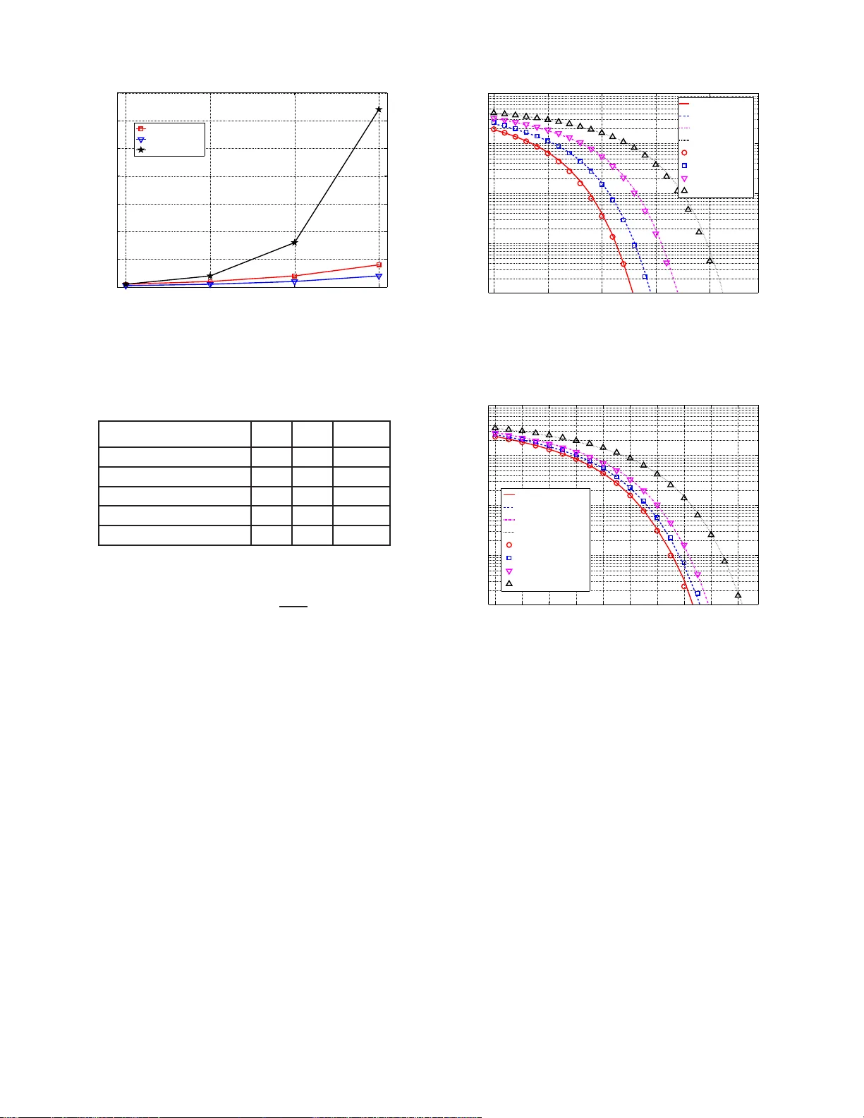
1 Performance Analysis of No n -DC-Biased OFDM Y ichen Li ∗ , Dobroslav Tsonev ∗ and Harald Ha as ∗ ∗ Institute for Digital Communicatio ns Joint Research Institute for Signal and Image Processing School of Engin eering The University of Edinburgh EH9 3JL, Edinburgh, UK { yichen . li, d.tsonev , h.h aas } @ed.ac.uk Abstract —The perfo rmance analysis of a nov el optical mod- ulation scheme is presented in this paper . The basic concept is to transmit signs of modulated optical orthogonal frequency division m ultiplexing (O-OFDM) symbols and absolute v alues of the symbols separately by two inf ormation carrying units: 1) indices of two light emitting diodes (LED) transmitters that repre sent p ositive and negativ e signs separately; and 2) optical intensity symbols th at carry the absolute values of signals. The new approach, r eferred as to non-DC-biased OFDM (NDC- OFDM), uses the optical spatial modulation (OSM) tech n ique to eliminate the effect of t h e clip ping d i stortion in DC-biased optical OF DM (DCO-OFDM). In addition , it can achieve similar advantages as th e con ventional unipolar modulation sch eme, asymmetrically clipped optical OFDM (A CO-OFDM), without using additional sub carriers. In this p aper , th e analytical BER perfo rmance is compared with the Monte Carlo result in order to prov e the reliability of the new method. Moreo ver , the p ractical BER perform ance of NDC-OFDM with DCO-OF D M and A C O- OFDM is compared fo r different constellation sizes to verify the improvem ent of NDC-OFDM on the spectral and power efficiencies. Index T erms —optical wireless communication, optical OFDM, optical sp atial modu lation, MIM O I . I N T RO D U C T I O N W I T H the rapid development of wireless serv ices and applications, since 2 000 wireless d ata rates hav e been growing exponentially . Some recent foreca sts indicate that 5 th generation (5 G) wireless systems will have speeds of 1 Gb ps b y 2 020 [ 1]. Despite the fact that the hardware of the system can satisfy the requir ement of the high speed transmission, the limited rad io f requen cy (RF) spectrum may not be sufficient to cop e with futur e d ata r ate d emands. As a viable comp lementary ap p roach, optical wireless commu- nication (OWC ) has gain ed significan t atten tion in part due to recent technological de velopments in solid state lighting technolog y [2]. The momentous advantage of O WC is that it offers almost infinite bandwidth ran ging from infr ared (IR) to ultraviolet (UV) i ncluding the v isible light spectr um [3]. Other imp ortant benefits of OWC are: license-f ree operation; high commun ication security; lo w- cost-fron t-ends; and no interferen ce to RF systems meaning that OWC an d RF systems can be used sim u ltaneously . In cu rrent visible ligh t co m municatio n (VLC) systems, high speed light emitting diodes (LEDs) are mainly used as trans- mitters. At the re c e i ver , h ighly sen siti ve photod iodes (PDs), such as positive-intrinsic-negative (PIN) d iodes, av alan che photo d iodes (APDs) and single-p hoton av alan c h e diodes (SP ADs) are u sed [4]. T o date, th e fastest wireless VLC system using a single LED can achieve sp e eds exceeding 3 Gb/s [5 ]. Howe ver, th e incoheren t light output of the LED mean s that informa tio n can only be encoded in the intensity le vel. As a co nsequen c e , only r eal-valued and positive sign a ls can be used for data mod u lation. This is in co ntrast to RF systems which m ake use of com plex valued and bi-po lar signals. Thus, VLC systems are usua lly c onsidered to b e m odulated as an in tensity mod ulation (IM) and direct detection (DD) system [ 6]. On- off ke ying (OOK), p ulse p osition mo dulation (PPM) and pulse amplitude modulation (P AM) are some of the common modulation schem e s used in conjunctio n with IM/DD systems [6]– [9]. Recen tly , the Optical Orthogo n al Frequency Division Multiplexing ( O-OFDM) m odulation scheme, treated as th e high - speed data transmission appro ach, can also applied in the context of IM/DD systems [10]–[14]. A. Optical OFDM For th e high-sp eed OWC sy stem, O-OFDM is used to handle severe ISI. The advantages of OFDM in O WC are same a s in RF wh ich are de scr ibed in [1 0], [15]. Howe ver , as th e O-OFDM is based on the I M /DD s ystem wh ich is limited to transmit real-v alued sign als, the set-up methods of each subcarrier are different between O-OFDM and the traditional OFDM system in RF . I n O-OFDM , during the signal generation p h ase, real- valued symbols can be achieved by impo sing Hermitian symmetry on the informa tio n frame be- fore the inverse fast Fourier transf o rm ( IFFT) op eration. Th is decreases the spectr al effi ciency by half. In gen eral, standard technique s to ensure positive o p tical signals are DC -biased optical OFDM (DCO-OFDM), asymmetrically clipped optical OFDM (AC O-OFDM) and unipolar OFDM (U-OFDM) [16], [17]. In DCO-OFDM, a DC-bias is added to the o riginal OFDM signal and the negative par t is clipp e d. Clipp ing in DCO-OFDM may cau se nonlinear d istortion [ 18]. If the DC- bias is incr eased to an o ptimal level, all of the sym bols will be positive but the hig her lev el requires mor e transmission power . In A CO-OFDM, the system inserts zeros on even subcar riers and modulate s only od d sub carriers. As a result, a gro up of antisym m etric real-valued OFDM symbols are obtained, 2 as shown in [18]. Th is allo w s a ny negative samp les to be clipped without distortion . Since only half o f th e subcarriers carry information bits, the spectral ef ficiency of A CO-OFDM is a b out half the spectral efficiency o f DCO-O FDM . In U- OFDM, the po siti ve par t of OFDM sym bols an d the negative part o f the symbols will b e tran smitted respectively [17]. The positive blo ck comes from the origin al OFDM signal with clipping th e negative part an d the negative block is genera ted in the s ame way . At the tr ansmitter, the positi ve block is transmitted first and the absolute value of the n egati ve block is then transmitted . Since the len gth o f th e OFDM fram e is doubled , U-OFDM has the same spec tr al efficiency as A CO- OFDM. B. Optical Spatial Modulation In c urrent 4G commu nication systems, OFDM mu ltiple- input mu ltiple-outpu t (MIMO) is used as an efficient and effecti ve method to satisfy the demand of high data rate transmission without I SI [ 19]–[21]. Examples o f MIMO tech- niques are vertical Bell Labs layered space-time (V -BLAST), Alamouti and spatial mod ulation (SM) [2 2]–[24]. Comp ared to V -BLAST and Alamouti, SM has better BER perf o rmance while achieving th e same spectral efficiency . In addition, about 90% reduc tio n in receiver complexity can be achieved [23]. For the VLC system, the optica l SM ( OSM) techn iq ue using IM/DD has been considered in [25]. I n OSM, within a ro om, multiple tra nsmitters a r e spa tially separated . Only one LED is activ ated at any time in stan ce and visible lig ht is emitted with a fixed f r equency and a certain o ptical power . Each tr ansmitter index carries log 2 ( N t ) bits when the numb er of transmitters is N t . In the IM/DD system, the value o f modu la ted signals can be transmitted by the certain optical power . Thus, th e conv entional modulatio n schemes can be used in OSM, a n d ev en O-OFDM. I n the conventional OSM-OFDM system, the indices of the transmitter s carry a par t o f info rmation bits, and modulated sign als, which car ry the o ther par t of info rmation bits, are tr ansmitted b y the active LE D. The detailed model of the con ven tional OSM-OFDM system h as b een introduced in [26]. C. NDC-OFDM A n ovel O-OFDM modula tio n sch eme designed for OSM is presented in [26], which comb in es the basic OSM-OFDM and the original O-OFDM modulato r , referred as to Non- DC-biased OFDM (NDC-OFDM). Th e new meth od aim s to eliminate the clipp ing distortion prob lem in DCO-OFDM an d increase th e spectra l efficiency wh ich is halved in A CO- OFDM and U- OFDM. In N DC-O FDM , after the DCO- O FDM modulatio n blo ck, symb ols are tr ansmitted b y different LEDs. The positiv e OFDM symbol is transmitted b y one LED and the negativ e sym bol is transmitted by another LED. As the LED can on ly transmit p ositiv e sign a ls, the ab solute value of the negativ e symbol is transmitted. Th u s, unlike the conv entional OSM-OFDM system, the indice s of transmitters in NDC- OFDM repr esent the signs of th e tr ansmitted sign al a n d the absolute value of th e signal is sent as optical in te n sity signals. As the DC-b ias and the bottom clipping d o not exist in NDC- OFDM, the system can sa ve energy . Despite the fact that NDC- OFDM uses two transmitters, the energy efficiency perform s better than conventional OSM-OFDM schemes wh en using the same n umber of tra nsmitters. Moreover , the VLC system trends to b e realized by multiple low power LEDs to achiev e higher transmission bit rate. The rest of this paper is organized as fo llows. The system model of NDC-OFDM is described in Sectio n II. Section III presents th e p erform ance a nalysis of NDC-OFDM. Section IV shows num erical and simulation results of the performa n ce analysis a nd the r esult o f a co mparison b etween NDC-OFDM and conventional OSM-OFDM in terms of th eir BER perfor- mances. Finally , Section V conclu d es this paper . I I . S Y S T E M M O D E L The NDC-OFDM system model is illustrated in Fig. 1 . This system mainly aims to solve the DC-bias distortio n p roblem in the DCO-OFDM mod ulation schem e. Using the ind ices o f LEDs to transmit signs of samples ensures th at tran smitted samples are positiv e and also saves transmission e nergy in order to in crease the spectral efficiency under a fixed power condition . A. Modula tion Pr o cedure At the transmitter, the inpu t bit stream is tra n sformed into complex symbols, X ( n ) , n = 0 , · · · , N / 2 − 2 , by an M -QAM modulato r . N is the nu mber of OFDM sub carriers. N / 2 − 1 QAM symb ols are then m odulated on to th e fir st half of an OFDM frame, X ( m ) , m = 0 , · · · , N − 1 , and the DC subcarrier (the first subcarr ie r ) is set to zer o. Then, Hermitian symmetry is impo sed on the seco nd h a lf o f the OFDM frame. Next, the mapp ed sub carriers are passed thro u gh an IFFT block. W ithout loss of g e nerality , th e following d e fin ition of in verse discrete Fourier tr ansform is u sed [10], x ( k ) = 1 √ N N − 1 X m =0 X ( m ) exp( j 2 πk m N ) . (1) After the N -IFFT o peration , th e complex QAM symbols become N real-valued OFDM samp les, x ( k ) , but th ey are still bipolar . In the conventional DCO-OFDM system, a DC b ias is added and the signal is then clipped to obtain the unipo lar sample. In pr actice, the value of th e DC bias, which is related to the average power of the OFDM sy mbols, is defin ed in [1 6] as B DC = α p E { x 2 ( k ) } , (2) where 10 log 10 ( α 2 + 1) is defined as the bia s level in dB which depend s on the co nstellation size. For the simple DCO-OFDM model, po sitive samples, which can be transmitted by LEDs, are ob tained by signal clipping after a fixed power for the D C bias is add ed. Howev er , th e add ed DC biased power increases the power co nsumption . Mor e im p ortantly , if the lev el of DC- bias is not eno ugh to ensure all th e sam ples positive, the signal clipping will c ause the bottom distortion p r oblem [27]. 3 Fig. 1. Block diagram of the NDC-OFDM system NDC-OFDM is a novel m o dulation sche me which can sa ve the transmission energy and mitig ate the bottom non linear distortion problem. I n NDC-OFDM, LEDs only send the absolute value of x ( k ) and the sign of th e symbol is rep- resented by the index of th e cor r espondin g LED. Accord ing to the work ing princip le o f OSM, o nly one L E D is activated during one sym bol time. If th e transm itted symbol is positive, the first L E D will be activ ated to send the symbol. If the symbol is negative, its absolute value will be sent by the oth e r LED. Since the absolute values of the ne gativ e samp les is transmitted, this system do es no t n eed additional transmission power to obtain po siti ve signals. Moreover, the signal clippin g is not exerted in NDC-OFDM beca use every sample is fitted for the LED-based system. In general, in a n OFDM-ba sed system a cyclic prefix (CP) is added to resist ISI before the samp les are transmitted , but in OW C the CP is shown to have a negligible effect on the electrical SNR r equireme n t a n d the sp ectral efficiency [28]. Therefo re, for simplicity , it is not considere d in the theoretical perfor mance analy sis in this study . Finally , th e d igital signa ls in SM fram e vectors, L 1 ( k ) a n d L 2 ( k ) , will be tran sf o rmed to analog signals and prepared to be transmitted by L E Ds. B. Optical Channel As shown in Fig. 2, th e converted o ptical signals will be transmitted by the corre sp onding LED over the o ptical MIMO channel H [ 25]. W ithout loss of generality , a simple N t × N r optical channel matrix is r ealized, H = h 11 h 12 · · · h 1 N t h 21 h 22 · · · h 2 N t . . . . . . . . . . . . h N r 1 h N r 2 · · · h N r N t , (3) where h N r N t is the chan n el DC g ain of a directed line-o f -sight (LOS) link between the receiver N r and th e tr ansmitter N t . The LOS lin k is considered in the system model, b ecause the multipath com ponen ts a re significan tly w e a ker and can thus be neglected. The chann el g ain is calcu lated as follows [ 6], h N r N t = ( β +1) A 2 πd 2 cos β ( φ ) T s ( ψ ) g c ( ψ ) co s( ψ ) , 0 ≤ ψ ≤ Ψ c 0 , ψ > Ψ c (4) Where β is related to Φ 1 / 2 which is the transmitter semiangle, by β = − ln 2 / ln(cos(Φ 1 / 2 )) , A is the detector ar e a of the PD, d is the distance between the receiver N r and the transmitter N t , φ is the radiant an g le, ψ is the incident an g le, T s and g c are the optical filter gain and the o pti- cal concentr a tor gain which d epend on the proper ties of the recei ver . C. Detection and Demodulatio n Throu g h the o ptical MIMO chan nel, co rrelated op tical sig- nals are detected and o btained by PD receivers. The received signal can b e written as y = Hs + w , (5) where y is the N r -dimension al received vector and s is the N t -dimension al transmitted signal vector . In this pap er , both N r and N t are set to two. In a d dition, w is the N r -dimension al noise vector which is assumed to be real-valued A WGN. After the received optica l OFDM sig nal is conv erted to an electrical signa l by PD, the ZF detection is used to re cover the transmitted symbols a s fo llows [ 29], g = H − 1 y , (6) where g is an N t -dimension al vector w h ich con tains the estimated transmitted symbo ls an d H − 1 denotes the inverse of the ch annel matrix H . I n this pap e r , it is assumed that the chan nel gain is known at the re ceiv er . The perfo rmance of NDC-OFDM is c o mpared with the con ventional O-OFDM approa c h in this study an d dif ferent detection meth ods will 4 not effect on the c omparison results. Even thou gh the MMSE detector can also be used in the NDC-OFDM system with the known chann el infor m ation and the no ise coe fficient, the ZF detector has been ch osen as a simple and convenient detection method [30]. Each eleme nt in g repr e sents th e detected OFDM signal which has been transmitted b y the co rrespond ing LED with A WGN added at th e recei ver . Before demo dulating th e received signal, there ar e two methods in which the orig inal bip olar OFDM signa l can be reconstruc ted. Both of the two metho ds are b ased on th e principle of the mo dulation scheme in NDC-O FDM . The detected signal rec e ived by the fir st PD is set to be transmitted by the first LED which sent the positi ve OFDM sam ple. The second PD achieves the absolute value of th e n egati ve sample. In NDC-OFDM, since only one LED is acti vated d uring one time slo t, o nly on e e lement in g carr ies the bit info rmation and the other on es are treated as no ises. According to the ru les above, th e first method is to subtract the n egati ve signal block from the positive one. Th is is the same as the demo dulation approa c h in ACO-OFDM. Howe ver, when re constructed in this way , the pro posed method perfo rms 3 dB worse th an bipolar OFDM fo r the same con stellation size. This is b e c ause the su b traction o f th e n egative block from the positi ve o ne doubles the A WGN variance f or each restored bipo lar OFDM signal. The o th er recon stru ction m e thod used in NDC-OFDM perfor ms a s ignificant im provement o n the power efficiency which has been pr oved in U-OFDM [17]. This m ethod mainly aims to estimate the index of th e activ e transmitter . The esti- mated index r epresents the sign o f the tran smitted informa tio n OFDM sample. The informatio n-carried sign al, afterwards, can be selected to re construct the bipolar OFDM signal. Compared with th e fo rmer app roach, this method will not double the A WGN variance for eac h estimated OFDM symbol. In particular, to estimate the indices o f the active transmitters, the SM de te c tor compar e s the values o f th e elements in g as follows, ˜ l ( k ) = arg max i ( G ( i, k )) , i = 1 , · · · , N t , (7) where G is the N t × N equa lized matrix wh ich contains all the estimated transmitted symbols and ˜ l is an N -dimen sio n al vector wh ich contain s all th e estimated ind ices. As no ted, there are two transmitters and two receiv ers. I f ˜ l ( k ) is equal to o ne, this m eans that the symbol r eceiv ed at the time instant k is transmitted from the first LED. There fore this symbol is a positive-v a lu ed OFDM symbol. If ˜ l ( k ) is tw o , a n egati ve symbol is transmitted by LE D 2 . As a consequ ence, the estimated OFDM symbols seq uence is x ′ ( k ) = G ( ˜ l ( k ) , k ) , ˜ l ( k ) = 1 , − G ( ˜ l ( k ) , k ) , ˜ l ( k ) = 2 . (8) In an ideal scenario , if there is no A WGN, x ′ ( k ) should be the same as x ( k ) . In th is paper, the sign- selected estimation has been ch osen. After recovering the OFDM sym bols, x ′ ( k ) is passed throu g h the co n ventional OFDM de modulatio n b lock to obtain recei ved QAM symbols, X ′ ( m ) = 1 √ N N − 1 X k =0 x ′ ( k ) exp( − j 2 π k m N ) . (9) The N / 2 − 1 data - carrying symbols in X ′ ( m ) can be extracted and then demodulated using a maximum likelihood (ML) detector in o rder to obtain the ou tput b it stream. I I I . P E R F O R M A N C E A NA L Y S I S The theoretical BER per forman ce of NDC-OFDM is com- puted and presented in this section in o rder to de monstrate the cor r ectness of experimental results. Moreover , the spectral efficiency of NDC-OFDM is analysed and com pared with the spectr a l efficiency of o ther OFDM m ethods in the OSM system. A. Theoretical P erforma nce o f NDC-OFDM T o calculate the theore tica l BER of NDC-O FDM , the following mathem atical n otations and fo rmulas should b e defined. I n this pape r , σ n is the standard deviation of the A WGN, i.e., σ n = p N 0 / 2 , wh ere N 0 / 2 is the variance of the A WGN.Th e constan t, σ s , is the standar d deviation of the real OFDM signals which hav e been modulated an d are ready to be tr ansmitted by L EDs. For the analytical calculatio n, σ s is defined as f ollow , σ s = r E b log 2 ( M ) N − 2 2 N N t , (10) where E b is the electrical energy p er bit. E b / N 0 is the metric of th e BER perfor m ance. φ ( x ) is the standard n ormal distribution pro bability density fun ction, i. e ., φ ( x ) = 1 √ 2 π e − x 2 2 (11) 1 ( x ) is the step fu nction, i.e., 1 ( x ) = 1 if x > 0 0 if x ≤ 0 (12) sgn( s ) is the sign fu nction, i.e., sgn( s ) = − 1 if s < 0 0 if s = 0 1 if s > 0 . (13) In following theoretical expre ssion s, a 2 × 2 MI MO c h annel is considered, H = h 11 h 12 h 21 h 22 . (14) Since th e attenuation gain of the channel has a limited ef fect on the results of the analytical BER performanc e , fo r simplicity , the coe fficients in H are nor malized to on e and th ey simply represent the corr e la tio n coefficients of the chann e l. T he ZF detection needs to use the in verse m atrix of th e channel matrix , H − 1 , to e liminate the channel effect on informatio n samp les. The in verse matrix is rep resented by C , i.e., 5 P r c ( s, n 1 , n 2 ) = ( 1 σ 2 n φ ( n 1 σ n ) φ ( n 2 σ n ) 1 ( | s | + ( c 11 − c 21 ) n 1 + ( c 12 − c 22 ) n 2 ) , s > 0 , 1 σ 2 n φ ( n 1 σ n ) φ ( n 2 σ n ) 1 ( | s | + ( c 21 − c 11 ) n 1 + ( c 22 − c 12 ) n 2 ) , s < 0 . (16) P r w ( s, n 1 , n 2 ) = ( 1 σ 2 n φ ( n 1 σ n ) φ ( n 2 σ n ) 1 ( −| s | − ( c 11 − c 21 ) n 1 − ( c 12 − c 22 ) n 2 ) , s > 0 , 1 σ 2 n φ ( n 1 σ n ) φ ( n 2 σ n ) 1 ( −| s | − ( c 21 − c 11 ) n 1 − ( c 22 − c 12 ) n 2 ) , s < 0 . (17) C = c 11 c 12 c 21 c 22 . (15) Based o n the theore tica l analysis metho d of th e nonlinear transmission in [17], the analysis in this study main ly a im s to calculate the prob a b ility of the cor rect a n d incorrect detection in which t he ef fects of the ZF detection and the nonlin ear OFDM d emodula tio n should b e taken into consider ation. I n NDC-OFDM, two receivers obtain op tica l O FDM samples over the MIMO chan nel at the same time. After th e ZF detection, the unipolar OFDM symbols are r e covered with th e enhanced A WGN. Sy mbols detecte d by the first PD co me f rom the first LED which ar e orig inally positive symbols. Symb ols detected by the second PD are transmitted by the second LED which a r e th e absolute values o f the negativ e symbols. I f ther e is no noise in the system, the received symbo ls should be the same a s the tran sm itted symbo ls. In the theor etical analy sis model, the A WGNs are co nsidered as two inde penden t random variables, n 1 and n 2 , which fo llow the standard nor mal distribution with the standa r d deviation, σ n . Since the ZF detection is used in the system, th e no ise is en hanced af te r removing the ch a n nel crosstalk. M ost impor tantly , th e A WGN in o ne receiver has an impact on the variance o f the noise in the other receiver . Consider ing this co ndition, the cor rectly detected pro bability for the identical sym bol is p resented in (16). This d epends on a ran dom value of n 1 , a r a ndom value of n 2 , the inverse matrix of the chan nel an d the original bipolar symb ol, s . T h e bipo la r OFDM s ymbols also follo w the Gaussian d istribution. Likewise, the inco rrectly detected probab ility is given in (17). W ith the identical n 1 , n 2 and s , the correctly detected OFDM sample is expressed as fo llow , x c = | s | + c 11 n 1 + c 12 n 2 , s > 0 , | s | + c 21 n 1 + c 22 n 2 , s < 0 . (18) For all po ssible values of n 1 and n 2 and the identical OFDM sample, the mean o f x c is, f c ( s ) = sgn( s ) R ∞ −∞ R ∞ −∞ x c P r c ( s, n 1 , n 2 ) d n 1 d n 2 R ∞ −∞ R ∞ −∞ P r c ( s, n 1 , n 2 ) d n 1 d n 2 . (19) Moreover , the variance of the correc tly detected sample has the following value, v c ( s ) = R ∞ −∞ R ∞ −∞ x 2 c P r c ( s, n 1 , n 2 ) d n 1 d n 2 R ∞ −∞ R ∞ −∞ P r c ( s, n 1 , n 2 ) d n 1 d n 2 − f 2 c ( s ) . (20) Based on the Central Limit T heorem (CL T), after the FFT is exposed in the OFDM demodu lation process, the v a r iance, v c ( s ) will be a part of the variance of the A WGN in the frequen cy doma in. For the detectio n of NDC-OFDM, the in- correct determin ation will enhan ce the v ariance of th e A WGN, but this enhancement is much less than th e detection metho d of the conventional A CO-OFDM which d oubles the variance. For incorrect d etection, the selected OFDM sample is calcu lated as, x w = c 21 n 1 + c 22 n 2 , s > 0 , c 11 n 1 + c 12 n 2 , s < 0 . (21) The m e an and the variance of this value have the f o llowing forms, f w ( s ) = − sgn( s ) R ∞ −∞ R ∞ −∞ x w P r w ( s, n 1 , n 2 ) d n 1 d n 2 R ∞ −∞ R ∞ −∞ P r w ( s, n 1 , n 2 ) d n 1 d n 2 , (22) v w ( s ) = R ∞ −∞ R ∞ −∞ x 2 w P r w ( s, n 1 , n 2 ) d n 1 d n 2 R ∞ −∞ R ∞ −∞ P r w ( s, n 1 , n 2 ) d n 1 d n 2 − f 2 w ( s ) . (23 ) Since the OFDM samples, s , fo llow a Gaussian distribution, for all possibility of s , th e average variances of th e co rrect and incorrect detections are, ¯ v c = Z ∞ −∞ v c ( s ) 1 σ s φ ( s σ s )d s, (24) and ¯ v w = Z ∞ −∞ v w ( s ) 1 σ s φ ( s σ s )d s. (25) These v ariances will constitute the v ariance of the A WGN in frequen cy domain. After the NDC-OFDM detection, the selected symb ols should be dem odulated to QAM symbols by FFT . For NDC- OFDM, the demo dulation procedur e is treated as a nonlinea r transform ation. Accord ing to the Bussgang theo rem [31], if an ind ependen t Gau ssian r andom variable, X , passes through a nonlin ear tr ansformatio n, f ( X ) , which has th e following proper ties, f ( X ) = α d X + Y E [ X Y ] = 0 α d = const , (26) where E [ . ] expresses the statistical expe ctation. Using the proper ties ab ove, the no nlinear distortion in an OFDM-ba sed system can be eq uiv alen t to a gain factor, α d , and an ad ditional noise, Y [ 17]. In NDC-OFDM, X is equ a l to th e value o f th e transmitted symbol, s , and Y is a n oise compone n t wh ich is a Gaussian ran dom variable non -correlated with X . After exposing FFT , the variance of Y will b e composed of the other 6 part of the variance of the A WGN in the frequ ency d omain and α d will enhan ce the mean value of the infor mation-ca r ried symbol in each modulated subcarrier . Accor d ing to 26, α d can be deriv ed as, α d = E [ X f ( X )] σ 2 X (27) where σ X is th e standard d eviation of X , which is e q ual to σ s in this stud y . Since the additio n al noise, Y , fo llows a Gaussian distribution with a zero me a n, the variance of Y can be calculated as, σ 2 Y = E [ Y 2 ] − E [ Y ] 2 = E [ Y 2 ] = E [( f ( X ) − α d X ) 2 ] = E [ f 2 ( X )] − α 2 d σ 2 X . (28) From (27) and (28), the values of the constant and the variance for the correct detection are expressed as, α c = R ∞ −∞ sf c ( s ) 1 σ s φ ( s σ s )d s σ 2 s , (29) y c = Z ∞ −∞ f 2 c ( s ) 1 σ s φ ( s σ s )d s − α 2 c σ 2 s , (30) where y c is the variance. For the incor rect detection , the constant, α w , and the variance, y w , are calculated as, α w = R ∞ −∞ sf w ( s ) 1 σ s φ ( s σ s )d s σ 2 s , (31) y w = Z ∞ −∞ f 2 w ( s ) 1 σ s φ ( s σ s )d s − α 2 w σ 2 s . (32) From (16), the prob a bility of th e corr ect d etection d uring an acti ve time slot is, d c = Z ∞ −∞ Z ∞ −∞ Z ∞ −∞ 1 σ s φ ( s σ s ) P r c ( s, n 1 , n 2 )d n 1 d n 2 d s (33) For a large num ber of samples in a NDC-OFDM f rame, the number o f correctly an d incorrectly d etected active samples have a ratio which corresp onds to the pr obabilities for correct and incor rect d etection. Accordin g to (26), the n onlinear trans- mission will ad d a ga in factor to the sam p le. For the theoretical analysis, the av erage value of the gain factor will en hance th e av erage energy o f the tran smitted bits. The average g a in factor is calculated as, ¯ α = d c α c + (1 − d c ) α w (34) As noted ab ove, th e variance of the detection, ¯ v c and ¯ v w , and the variance of the non linear transmission, y c and y w will constitute the a verage n o ise v ariance of the system in the frequen cy do main, i. e. , ¯ N = d c ( ¯ v c + y c ) + (1 − d c )( ¯ v w + y w ) (35) Thus, the average SNR elec per bit can be achieved fro m the known value o f E b , elec and th e calculate d values of ¯ α and ¯ N as, SNR elec = ¯ α 2 E b , elec ¯ N (36) Using the an alytical expression for the BER perfor mance of M − QAM O-OFDM in [ 18], the theo retical BER p erform ance of NDC-OFDM can b e calculated as, BER NDC = 4( √ M − 1) √ M log 2 ( M ) Q r 3 log 2 ( M ) M − 1 SNR elec ! + 4( √ M − 2) √ M log 2 ( M ) Q 3 r 3 log 2 ( M ) M − 1 SNR elec ! (37) B. Spectral E fficiency Compa rison NDC-OFDM is realized in the OSM system which can also ap ply A CO-OFDM and DCO-OFDM as th e modulatio n schemes. For fair c o mparison s, NDC-OFDM, A CO-OFDM and DCO-OFDM are built with an OSM system. For NDC- OFDM, the ind ices of LEDs is used to carry the sign in- formation . For A CO-OFDM a n d DCO-OFDM , the in dices carry add itional infor mation bits accordin g to the conventional principle of the OSM system. For a n ormal OSM system with the simple M − QAM, the spectral efficiency is calcu lated by considerin g bo th the transmitted sig n al info rmation bits and the in dices-carried bits, i.e., R OSM = log 2 ( M N t ) bits / s / Hz [25]. For NDC-OFDM, since the Her mitian symmetry o f O - OFDM decre ases the spectral efficiency by half and th ere is no info r mation bit carried b y the indices, th e refore the sp e ctral efficiency of NDC-OFDM is define d as, R NDC − OFDM = N − 2 2 N [log 2 ( M 1 N t ) − 1 ] bits / s / Hz , (38) Since in NDC-OFDM two different signs of the samp les should b e represented r espectively , th e n umber of th e LE Ds, N t , should b e even. For DCO-OFDM in the OSM system, the spectral efficiency is halved by the He r mitian symmetr y , so it is expressed as, R DCO − OFDM = N − 2 2 N log 2 ( M 2 N t )bits / s / Hz . (39) In ACO-OFDM, becau se o nly h alf of the sub carriers are mod- ulated, the spectral efficiency should have an addition al 50 % reduction . I n the OSM system, the actu al spectral efficiency of A CO-OFDM is, R AC O − OFDM = 1 4 log 2 ( M 3 N t )bits / s / Hz . (40) In 3 8, 39 and 4 0, M 1 , M 2 and M 3 denote the co nstellation size of QAM in the thr e e O- OFDM modulatio n schemes respectively . In this study , the size of the OFDM frame, N , is set to 20 4 8, so the coefficient, N − 2 2 N , in (3 8) and (39) can be treated as 1/2 . Wh e n NDC-OFDM, DCO-OFDM a nd A CO- OFDM in th e OSM system have the same spectr al efficien- cies,i.e., R NDC − OFDM = R DCO − OFDM = R AC O − OFDM , the constellation sizes of these three meth ods have the following relationship, 7 0.5 1 1.5 2 0 20 40 60 80 100 120 140 Spectral Efficiency (bit/s/Hz) QAM Constellation Size NDC-O FDM DCO-O FDM A CO -OFDM Fig. 2. Constell ation size vs. spectral effic ienc y for NDC-OFDM, DCO- OFDM and ACO-OFDM in the OSM system T ABLE I C O N S T E L L A T I O N S I Z E S C O M PAR I S O N ❤ ❤ ❤ ❤ ❤ ❤ ❤ ❤ ❤ ❤ ❤ SE (bits/s/Hz ) Method NDC DCO A CO 3.5 128 64 8192 4 256 128 32768 4.5 512 256 131072 5 1024 512 524288 5.5 2048 1024 2097152 M 1 = 2 M 2 = p 2 M 3 . (41) Fig. 2 shows that constellation sizes are used to reach the same spec tr al efficiencies between 0 .5 bits/s/Hz and 2 bits/s/Hz for NDC-OFDM, DCO-OFDM and A CO-OFDM in the OSM system. It can be seen tha t NDC-OFDM needs a little higher constellation size to re ach the same spectra l efficiency as DCO-OFDM. Most impo rtantly , if the spectral efficiency of A CO-O FDM is equa l to the spectral efficiency of NDC- OFDM, th e constellation size will increase expo nentially which costs the system co mplexity . For the high spectral efficiencies, such as between 3.5 bits/s/Hz an d 5 .5 bits/s/Hz, the incre a se o f the con stellation size of A CO-OFDM becomes very large as shown in T able I. Although the c o nstellation size can be as large as required to achie ve the high er spectral efficiency , the d ata in the table f or A CO-OFDM is unrealistic and unattainable. For th e hig h speed optical tr a n smission, NDC-OFDM and DCO-OFDM are mo re realistic. I V . N U M E R I C A L A N D S I M U L AT I O N R E S U LT S A. Analytica l Results As noted in Section III, simple correla ted ch annels are considered to test th e corr ectness of the theor etical analysis. Symmetrical ideal channels ar e set as follows, 0 5 10 15 20 10 −3 10 −2 10 −1 10 0 E b / N 0 (dB) BER H 1 Simulation H 2 Simulation H 3 Simulation H 4 Simulation H 1 Theory H 2 Theory H 3 Theory H 4 Theory Fig. 3. Comparison between anal ytica l and simulati on results for symmetrical ideal channels: H 1 , H 2 , H 3 , H 4 0 2 4 6 8 10 12 14 16 18 10 −3 10 −2 10 −1 10 0 E b / N 0 (dB) BER H 5 Simulation H 6 Simulation H 7 Simulation H 8 Simulation H 5 Theory H 6 Theory H 7 Theory H 8 Theory Fig. 4. Comparison between analyti cal and simulation results for asymmet- rical ideal channels: H 5 , H 6 , H 7 , H 8 H 1 = 1 0 0 1 , H 2 = 1 0 . 3 0 . 3 1 , H 3 = 1 0 . 5 0 . 5 1 , H 4 = 1 0 . 7 0 . 7 1 . (42) The c o efficients in (4 2) reflect the correlatio n of optical channels. A high value of coef ficient ind icates a high le vel of cor relation. W ithout loss of generality , asym metrical ideal channels are also tested in this study , H 5 = 1 0 0 0 . 7 , H 6 = 1 0 0 . 3 0 . 7 , H 7 = 1 0 . 5 0 0 . 7 , H 8 = 1 0 . 5 0 . 3 0 . 7 . (43) Since the co nstellation size can be treate d as a factor wh ich will n o t e ffect on the re su lt of the integration in the theo retical 8 0 5 10 15 20 25 10 −4 10 −3 10 −2 10 −1 10 0 BER E b / N 0 (dB) NDC 1.5b/s/Hz NDC 2b/s/Hz AC O 1.5b/s/H z AC O 2b/s/Hz DCO 5 dB 1.5b/s/Hz DCO 5 dB 2b/s/Hz DCO 7 dB 1.5b/s/Hz DCO 7 dB 2b/s/Hz Fig. 5. NDC-OFDM, A CO-OFDM and DCO-OFDM Performance Compar- ison ov er H Prac 1 0 5 10 15 20 25 10 −4 10 −3 10 −2 10 −1 10 0 BER E b / N 0 (dB) NDC 1.5b/s/Hz NDC 2b/s/Hz AC O 1.5b/s/H z AC O 2b/s/Hz DCO 5 dB 1.5b/s/Hz DCO 5 dB 2b/s/Hz DCO 7 dB 1.5b/s/Hz DCO 7 dB 2b/s/Hz Fig. 6. NDC-OFDM, A CO-OFDM and DCO-OFDM Performance Compar- ison ov er H Prac 2 expressions, 1 6-QAM is chosen in the implemen tation an d fo r simplicity , the variance of th e noise, σ n , is set to √ 0 . 01 . Fig. 3 shows the c o mparison b etween an alytical an d sim- ulation results for the symmetr ical id e a l channe ls. The per - forman ce of the theoretical mod el for the asym m etrical ideal channels is co mpared with Monte Carlo simu lations in Fig. 4. It c an be seen that the analytical mo d el and the simulations show close agreem ent. B. NDC-OFDM, ACO-OFDM and DCO-OF DM P erformance Comparison The Monte Carlo simulatio n results for NDC-OFDM, ACO- OFDM and D CO-O FDM a re shown in this section. T h e BER perfor mance of ND C-OFDM is com pared with ACO-OFDM and DCO-OFDM over d ifferent practical op tical MI MO chan - nels which are chosen from [2 9]. In [29], a generic 4 × 4 indoor scen ario is co nsidered with intensity mod ulated optical wireless links with LOS cha r acteristics. In this pap er , despite the fact that MIMO channels with a larger size can b e realized in ND C-OFDM a nd OSM-OFDM, 2 × 2 optical MIMO c h an- nels a re con sidered to test prop erties and a d vantages simply and easily . T hus, 2 × 2 o ptical M IMO link s are extrac ted from original 4 × 4 optical channels, takin g into accoun t the symmetrical and a symmetrical cases, H Prac 1 = 10 − 5 × 0 . 1889 0 . 07 13 0 . 0713 0 . 18 89 , H Prac 2 = 10 − 5 × 0 . 3847 0 . 18 89 0 . 1889 0 . 38 47 , H Prac 3 = 10 − 5 × 0 . 1889 0 . 07 13 0 . 1157 0 . 18 89 , H Prac 4 = 10 − 5 × 0 . 3847 0 . 26 91 0 . 1889 0 . 38 47 . (44) H Prac 1 , H Prac 2 , H Prac 3 and H Prac 4 represent simple practical optical MIMO cha nnels in the indoor scenario . Without loss of fairn e ss, the sp e ctral efficiency of these three metho d s should be same in ord er to co mpare po wer efficiencies. In the com parison, spectral ef ficiencies are set to 1.5 b/s/Hz a nd 2 b/s/Hz. Accordin g to (4 1), 8-QAM an d 16 -QAM ar e thus chosen in the si mulation of NDC-OFDM; these are doub le than the c o nstellation size of DCO-OFDM; an d f or AC O- OFDM, the modulatio n order s are 32 and 1 28. As noted in Section II, a fixed le vel of DC-bias needs to be adde d in DCO- OFDM. The lower le vel migh t cause the nonlinear d istortion and the h igher le vel would be energy inefficient. T o sh ow these two cases and to simulate a real situatio n, 5 dB and 7 dB DC- bias are chosen in the implem entation. Fig. 5 and Fig. 6 show the perf ormance o f NDC-OFDM, A CO-O FDM and DCO-OFDM with OSM over th e sym met- rical o ptical MIMO channels, H Prac 1 and H Prac 2 . It sho ws that when the spectral efficiency is 1.5 b/s/Hz, NDC-OFDM has aro und 3.5 dB power ef ficiency better than th e 5 d B DCO- OFDM a n d n e a rly 5 dB better than A CO-OFDM an d the 7 dB DCO-OFDM. In this case, there is no no nlinear distortio n in DCO-OFDM. Howe ver , when the spectr al efficiency is 2 b/s/Hz, th e nonlinear distortion appears in the BER perfor- mance of the 5 dB DCO-OFDM. Moreover , at that time, NDC- OFDM ca n save 7 dB energy com pared with DCO-OFDM. It m e ans that with th e inc r ease o f the spectral efficienc y , the perfor mance of NDC-OFDM is c losed to the unipo lar line an d this is shown in [17]. H Prac 2 is also a sy m metrical chann el but the correlation is different with H Prac 1 . Fig. 6 in dicates the perfor mance of the three methods over H Prac 2 . It seems that the chang e of the correlation of the channel may not chan ge the relationship between the perfo r mance of each m ethod. NDC- OFDM is also th e m ost power -sa ving m ethod in this case. The p erform a n ce of NDC-OFDM , A CO-OFDM and DCO- OFDM over th e asymmetrical chan n els is indicated in Fig. 7 and Fig. 8 . As shown in Fig. 7, for the 1. 5 b/s/Hz spe c tr al efficiency , the NDC-OFDM can save 5 dB energy more than 5 dB DCO-OFDM and a round 7 dB mor e than 7 dB DCO- OFDM and A CO-OFDM in H Prac 3 . In the 2 b /s/Hz case, when BER = 10 − 4 , there is a 9 dB improvement between NDC-OFDM and 7 dB DCO-OFDM. NDC-OFDM gives better power efficiency than the other two methods. I n the higher co rrelation ch annel, H Prac 4 , the improvement increases 9 0 5 10 15 20 25 10 −4 10 −3 10 −2 10 −1 10 0 BER E b / N 0 (dB) NDC 1.5b/s/Hz NDC 2b/s/Hz AC O 1.5b/s/H z AC O 2b/s/Hz DCO 5 dB 1.5b/s/Hz DCO 5 dB 2b/s/Hz DCO 7 dB 1.5b/s/Hz DCO 7 dB 2b/s/Hz Fig. 7. NDC-OFDM, A CO-OFDM and DCO-OFDM Performance Compar- ison ov er H Prac 3 0 5 10 15 20 25 10 −4 10 −3 10 −2 10 −1 10 0 BER E b / N 0 (dB) NDC 1.5b/s/Hz NDC 2b/s/Hz AC O 1.5b/s/H z AC O 2b/s/Hz DCO 5 dB 1.5b/s/Hz DCO 5 dB 2b/s/Hz DCO 7 dB 1.5b/s/Hz DCO 7 dB 2b/s/Hz Fig. 8. NDC-OFDM, A CO-OFDM and DCO-OFDM Performance Compar- ison ov er H Prac 4 to 10 d B (Fig. 8 ). Moreover , whe n the hig hest correlatio n channel, H Prac 4 , is con sidered, NDC-OFDM has the g reater superiority over DCO-OFDM and AC O-OFDM. Th is mea n s that the transmission method of NDC-OFDM performs the ability of the anti-cr osstalk better than the con ventiona l O- OFDM methods in th e OSM system . V . C O N C L U S I O N S In this paper , th e o retical and p ractical perf ormance s of a novel u nipolar mod ulation method , called NDC-OFDM, is analysed. The new method combines O-OFDM with SM an d has been a pplied to the OWC system. Due to the Bussgan g theorem and th e CL T , the closed -form analytica l p erform a nce of NDC-OFDM in A WGN chann els has been derived. As a re- sult, an equation f or th e elec tr ical SNR p er b it, wh ich pr esents a memory less non linear distortio n analysis processing , has been pr esented to calculate the theoretical BER performan ce o f NDC-OFDM. In b oth id e al an d pr actical chan nels, the derived BER result matc h es the Mon te Carlo numerica l result clo sely . In compar isons of simulatio n p erform ances, NDC-OFDM exhibits the capab ility for achieving hig her ene rgy efficienc y than the conv entional OFDM- based mod ulation schemes ap - plied in the OSM system: D CO-O FDM and ACO-OFDM. Compared with DCO-OFDM, the new m e thod solves the clipping distortio n prob lem caused by the high level o f th e DC- bias. Additionally , it decr eases the power consum ption with less reduction in spe c tr al efficiency as ACO-OFDM. There- fore, when VLC systems ar e developed to wards equipped with multiple LE Ds to fu lfill minim um lightin g con ditions, NDC- OFDM will be used as an effecti ve and efficient modulation scheme. A C K N OW L E D G E M E N T R E F E R E N C E S [1] H. M. A. Gohil and S. K. Patel, “5G tec hnology of mobile communi ca- tion: A survey ,, ” in 2013 International Confer ence on Intellig ent Systems and Signal P r ocessing (ISSP), , pp.288-292, Mar . 2013. [2] H. Elgala, R. Mesleh, and H. Haas, “Indoor Optical Wire less Commu- nicat ion: Potentia l and State-of-t he-Art, ” IEEE Commun . Mag. , vol. 49, no. 9, pp. 56–62, Sep. 2011, ISSN: 0163-6804. [3] R. Mesleh, R. Mehmood, H. Elgala, and H. Haas, “Indoor MIMO Optical W ireless Communic ation Using Spatial Modulation , ” in IEEE Internati onal Confere nce on Communications (ICC) , Cape T o wn, South Africa, May 22–27 2010, pp. 1–5. [4] E. Fisher , I. Underwood , and R. Henderson, “ A reconfigurabl e single- photon-c ounting integra ting recei ver for optical communica tions, ” IEE E J ournal of Soli d-State Cir cuits , vol . 48, no.7, pp. 1638–1650, July 2013. [5] D. T s one v , H. Chun, S. Rajbha ndari, J. McKe ndry , S. V idev , E. Gu, M. Haji, S. W atson, A. Ke lly , G. Faulkner , M. Dawson, H. Haas, and D. O’Brien, “ A 3-Gb/s Single-LED OFDM-Based Wireless VLC Link Using a Gallium Nitri de uLED, ” in IEEE Photonics T echnol ogy Lett ers , vol.26, no.7, pp.637-640, April 1, 2014. [6] J. M. Kahn and J. R . Barry , “W ireless Infrared Communi catio ns, ” Pr oceed ings of the IEEE , vol. 85, no. 2, pp. 265–298, Feb . 1997. [7] A. Mahdiraji and E. Zahedi, “Comparison of Selected Digital Modula- tion Schemes (OOK, PPM and DPIM) for W ireless Optical Communica- tions, ” in In the Pro ceedi ng of the 4 th Student Confer ence on Researc h and Deve lopment (SCOReD 06) , Jun. 27–28, 2006, pp. 5–10. [8] S. G. Wil son, M. Brandt-Pea rce, Q. Cao, and M. Baedk e, “Optica l Repeti tion MIMO Transmissio n with Mult ipulse PPM, ” IEEE Journa l on Select ed Are as in Communication s , vol. 23, no. 9, pp. 1901–191 0, Sep. 2005. [9] S. C. J. Lee, S. Randel, F . Breyer , and A. M. J. Koon en, “P AM-DMT for Intensity-Modu lated and Direct-Det ecti on Optical Communicati on Systems, ” IEE E P hotonic s T echnolo gy Letters , vol . 21, no. 23, pp. 1749– 1751, Dec. 2009. [10] J. Armstrong, “OFDM for Optical Communicat ions, ” IEEE/OSA Journal on Lightwave T ech nolo gy (IEEE /OSA JLT) , vol. 27, no. 3, pp. 189–204, Feb . 2009. [11] R. Mesleh, R. Meh mood, H. Elgala, a nd H. Haas, “An Overv ie w of Indoor O F D M/DMT Optical W ireless Communicati on Syste ms, ” in 7th IEEE, IE T Internat ional Symposium on Communicat ion Systems, Network s and Digital Signal Proc essing (CSNDSP) , Mewca stle, U. K., 21–23 Jul. 2010, pp. 1–5. [12] H. Elgala, R. Mesleh, H. Haas, and B. Pricope, “OFDM V isible Light W irel ess Communication Based on W hite L EDs, ” in P r oc. of the 64th IEEE V ehicular T echno logy Confer ence (VTC) , Dublin, Ireland, Apr . 22–25, 2007. [13] R. Mesleh, H. Helgala, and H. Haas, “Performance Analysis of Indoor OFDM Optical W ireless C ommunicati on Systems, ” in Pr oc. of the W ire less Communications and Networkin g Confer ence (WCNC) , IEEE. Paris, France: IEEE, Apr . 1–4 2012, to appear . [14] X. Li, J. V ucic, V . Jungnicke l, and J. Armstrong, “On the Capacity of Intensit y-Modulat ed Direct-Det ectio n Systems and the Informati on Rate of A CO-OFDM for Indoor Optical Wi reless Applic ations, ” IEE E T ransaction s on Communication s (IEEE TCOM) , vol. 60, no. 3, pp. 799–809, Mar . 2012. [15] S. K. Chaudhury , “OFDM Basics, ” Lecture Notes, International Uni ver - sity Bremen, Nov . 2005. [16] J. Armstrong and B. J. C. Schmidt, “Compari son of Asymmetricall y Clippe d Optical OFDM and DC-Biased Optical OFDM in A WGN, ” Communicat ions Letters, IEEE , vol. 12, no. 5, pp. 343–3 45, May 2008. 10 [17] D. T sone v , S. Sinanovi ´ c, and H. Haas, “Nove l Unipolar Orthogonal Frequenc y Divisi on Mult iple xing (U-OFDM) for Optica l W ireless, ” in Pr oc. of the V ehicular T echnol ogy Confer ence (VTC Spring) , IE E E. Y okohama, Japan: IEE E , May 6–9 2012. [18] S. Dimitrov , S. Sinano vic, and H. Haas, “Clip ping Noise in OFD M- based Optical W ireless Communication Systems, ” IEEE T ransac tions on Communic ations (IEEE TCOM) , v ol. 60, no. 4, pp. 1072–10 81, Apr . 2012. [19] A. T echnologi es, LTE and the Evolution to 4G W ir eless: Design and Measur ement Challeng es , M. Rumney , Ed. John Wi le y & Sons, 2009. [20] A. Osseiran, V . Stan ko vic, E. Jorswieck, T . W ild, M. Fuchs, and M. Olsson, “A MIMO Framew ork for 4G Systems: WINNER Concept and Results, ” in Proc. IEEE W orkshop Signal P r ocessin g Advances W ire less Communication s (SP A WC 2007), Helsinki, Finl and , Jun. 2007. [21] Motorola Inc., “Dri ving 4G: WiMAX & L TE, ” Motorola Inc., posi- tioning paper , Retrie ved Feb. 19, 2009, from http://www .motorola.com, 2007. [22] P . W olniansky , G. Foschini, G. Golden, and R. V alenz uela, “V -BLAST: an Archite cture for Realizi ng very High Data Rates ove r the Rich- Scatte ring Wi reless Channel, ” in Unino Radio-Scie ntifique Interna- tionale (URSI) Intern. Symp. on Sig nals, Systems, and Electr onics (ISSSE) , Sep. 29–Oct. 2, 1998, pp. 295–300. [23] R. Mesleh, H. Haas, S. Sinano vi ´ c, C. W . Ahn, and S. Y un, “Spatial Modulat ion, ” IEEE T ransacti ons on V ehicul ar T echnolo gy , vol. 57, no. 4, pp. 2228 – 2241, Jul. 2008. [24] P . Y ang, Y . X iao, B. Zhou, and S. Li, “Initial performance e valuat ion of spatial modulation ofdm in lte -based systems, ” in Communicat ions and Networki ng in China (CHINA COM), 2011 6th International ICST Confer ence on , aug. 2011, pp. 102 –107. [25] R. Mesleh, H. E lgala, and H. Haas, “Optical Spatial Modulation, ” IEEE/OSA Jou rnal of Optical Communicati ons and Networking , vol. 3, no. 3, pp. 234–244, Mar . 2011, ISSN: 1943-0620. [26] Y . Li, D. Tsone v , and H. Haas, “Non-DC-biased OFDM with Opti cal Spatial Modulat ion, ” in 2013 IEEE 24th International Symposium on P ersonal Indoor and Mobile Radio Communications (PIMRC) , pp.486- 490, 8-11 Sept. 2013. [27] S. Dimitro v , S. Sinanovic , and H. Haas, “A Comparison of OFDM-based Modulat ion Sche mes for OWC with Clipping Distortion , ” in Pr oc. of the 2nd Optical W irele ss Communicati ons (O WC) W orkshop in conjunct ion with IEEE Global T elecommu nicati ons Confer ence (IEEE GLOBECOM 2011) , Houston, T exas, USA, 5–9 Dec. 2011. [28] H. Elgal a, R. Mesleh, and H. Haas, “Prac tica l Consideratio ns for Indoor W irel ess Optical System Implementati on using OFDM, ” in P r oc. of the IEEE 10th Interna tional Confere nce on T elec ommunicat ions (ConT el) , Zagreb, Croati a, Jun. 8–10 2009. [29] T . Fath, J. Klaue, and H. Haas, “Coded Spatial Modulation applie d to Optical W irele ss Comm unications in Indoor E nviro nments, ” in IEEE Pr oc. of the W irel ess Communicat ions and Networking Conf er ence (WCNC) . Paris, France: IEEE, Apr . 1–4 2012, pp. 1000 – 1004. [30] A. Klein, G. K. Kaleh, and P . W . Bai er , “Zero forcing and minimum mean-square -error equal izat ion for multiuser detection in code-di vision multiple -acce ss channels, ” IEEE Transac tions on V ehicul ar T echnolo gy , vol. 45, no. 2, pp. 276–287, May 1996. [31] J. Bussgan g, “Cross Correlat ion Function of Amplitude-Distort ed Gaus- sian Signa ls, ” Researc h Laboratory for Electron ics, Massachusett s Insti- tute of T echn ology , Cambridge, MA, T echni cal Report 216, Mar . 1952.
Original Paper
Loading high-quality paper...
Comments & Academic Discussion
Loading comments...
Leave a Comment