Broadband Cyclic-Symmetric Magnet-less Circulators and Theoretical Bounds on their Bandwidth
In this paper, we explore theoretically and experimentally broadband spatiotemporally modulated (STM) magnet-less circulators realized by combining three-port non-reciprocal junctions with three identical bandpass filters. We develop a rigorous theor…
Authors: Ahmed Kord, Dimitrios L. Sounas, Zhicheng Xiao
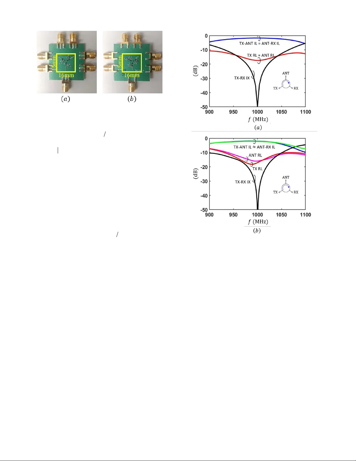
Submitted to the IEEE Transactions on Microwave Theory and Techniques 1 Abstract — In this paper , w e explore theoretically and experim entally broad ban d spa tiotem po rally m odu lated (STM) m agnet-less circulato rs realized by com binin g three-port non-re ciproca l junctions w ith three identica l ban dpass filters. We develo p a rigorous the ory for the p ropo sed c ircuit, which a llows to optim ize its design and to derive a global bou nd on the ma ximum possib le bandwidth ( BW ). We verify our theory with simulation s and m easur em ents of a p rinted circuit board (PCB) pro totype based on a differe ntial wye junction and second-ord er Ch ebyshev band pass filters, resu lting in a measu red fraction al BW of 13.9 % at a center frequen cy of 1 GHz. Index Terms — Bandwidth, Bode-Fano, c irculator , filters , m agnetless, STM. I. I NT RODUCT I ON ECIPROCITY is a general principle governing the f act that signal transmiss ion between two points in space is identical in either direction regardless of the co m plexity of the intermediate channel. It ap plies to a bro ad range o f materials, under the conditions that they are non-gy rotropic, passive, linear, and tim e-invariant [1]-[3]. Breaking any of these conditions allows the implementation of non-recipro cal components, such as circulators , iso lators, and gyrators, which have num erous applications in modern comm unication system s [4]-[10] . Recently, magnetless implementations of such components based on linear periodically time-varying circuits [11]-[38 ] have received significant attention, as they w ere show n to o vercome the weight, size, and cost challenges of magn etic d evices [39] -[43], wh ile satisfying the requirements This paper is an expanded version of an abstract p re sented at th e 2018 I nternational Microwave Sy mposium, Philadelphia, PA, USA, 10-15 June 2018 . The authors ar e with the Department of Electrical and Compu ter Engineering, University o f Te xas at A ustin, Austin, TX 78712, U.S.A. A . A . is also w ith the Photonics I nitiati ve , A dvanced S cience Research Center, with the Physics Program, G raduate Ce nter, and with the Dep artment of El ectrical Engineering, City Colle ge of New York, City University of New York, New York, NY 10 031, U.S.A . (corresponding author: A. A ., +1.212.413.32 60; e-mail: aalu@gc.cuny.edu ). This work w as supp or ted b y the IEEE Microwav e Theory and Techniques Society Graduate Fello wship, the Qualcomm I nnovation F ello wship, the Air Force Office of Scientific Research, th e Defense Advanced Rese arch Projects Agency , Silicon Audio, the Simons Foundation, and the National Sci ence Fo undation. A. A. is curre ntly the Chi ef Technology Officer of Silicon Audio RF Circulator. The terms of thi s arrangement have been revie wed a nd approved by The Uni ve rsity of Texas at Austin and the City University of New York in accordance with its p ol icy on objecti vity in research. on all other essential metrics. I n p articular, [28] and [2 9] presented radio-frequency (RF) circulators that can simu ltaneously achieve low transmis sion loss, excellent matchin g, large isolatio n, h igh power handling and linearity, low noise figure, and good harmonic response, all at a small form factor and lo w modulation frequency and amplitude. These cir cuits are also co m patible with standard CMOS technologies, wh ich permits further integration and cost reduction for large-scale prod uction. Nevertheless, this remarkable performance was maintained over a relatively narrow fractional bandw idth ( BW) of only a few percent. While this BW m ay be suff icient for a plethora of applications su ch as WiFi, RFID, and cellular co m m unication, it is still highly desirable to increase it further for broadband scenarios, such as radar systems and fu ture ultra-w ideband rad ios. The d escribed ST M circulators have been based on connecting bandpass or bandstop resonator s in a wye or a delta topology, respectively, w hile m odulating their natural oscillation frequencies with a particular phase pattern [28] . The instantaneous B W in either topo logies is limited b y the modulation parameters (particularly the m odulation f requency), the order of the constituent resonators , and the loaded quality factor. It w as show n in [28], [29] that first-order resonators, i.e., series or parallel LC tanks, with 1 0-20% m odulation frequency and 50 Ohm term ination can lead to a B W of 3~4% at best in practice. In order to improve this further, o ne so lution is to increase the modulation frequency, yet this would increase power consumption, prohibit integration using thick-oxide CMOS technologies which can handle high po w er, and complicate scaling the center frequency to the mm-w ave band . Another solution is to u se transf ormers to d ow nconvert the typical 50 Ohm impedance of the ports to a smaller value, thus decreasing the loaded quality factor and broad ening the junction ’s resonance. However, the r equired modulation amplitude in this case may become unr ealistic, since it has to increase w hen the loaded Q decreases in order to m aintain large isolation ( IX ) and small insertion loss ( IL ) [28]. Alternatively , one co uld increase the order of the constituent resonators so that the junction supports more modes (two degenerate modes at each pole) which, consequently, can be d esign ed to provide isolation over a larger BW. While th is is indeed a viable option, the main challenge is that it increases the circuit com plexity. A simpler ap p roach to broaden the bandwidth of magn etless ST M circulators was introduced in [32] based on Broadband Cyclic-Symmetric Magnet-les s Circulators and Theoretical Bounds on t heir Bandwidth Ahmed Kord, Student Member, IEEE , Dimitrios L. Sounas, Senior Member , IEEE , Z hicheng Xiao, Student Member , IEEE , and Andrea Alù, Fel low , IEEE R Submitted to the IEEE Transactions on Microwave Theory and Techniques 2 combining narrowband non-recip rocal junctions with passive bandpass filters. T his was inspired b y semi-empirical techniques co m monly used with magnetic devices [42] , [43] . Nevertheless, the results in [32] were only b ased on heuristic simu lations with out an experimental verification nor a theoretical analysis that can help m axim ize the BW . In this paper, we develop a rigorous theory for bro adband cyclic-sy mmetric magn etless circulators that not o nly provides a system atic design procedure to optim ize th e performance, but it also allows to d erive bounds o n the maxim um possible BW. Furtherm ore, an exper im ental validation is presented , achieving a 20 dB IX BW of 1 3.9% which is six times lar ger than our previously reported results [28 ]-[32]. This paper is organized as follows. In Section II, we develop the theory o f broadband ST M circulators. Without any loss of generality, we focus on the differential curr ent-m ode topology [29] keeping in mind that the analysis can be extended in a straightforw ard manner to any cyclic -sy mmetric, passive, and IM -free circulator. In the same section, we find a b ound on the ma ximum BW that can b e achieved and study the impact of changing th e ST M biasing parameters. In Section III, we present simulated and measured results for a P CB p rototype at 1 GHz. Finally, w e draw our conclusions in Section V. II. T HEORY A. Network Analysis of the Non-Reciprocal Ju nction Fig. 1 (a) shows the proposed broadband magnetless circulator, which consists of a narrowband ST M j unction and three identical bandpass filters, one at each port of the junction . We will assume in this paper that the narro w band junction is based on the differential current-mode top ology [2 9] shown in Fig. 1(b), w herein the variable capacitance n C is given by 0 0 cos 1 2 3 , 1 , 2, 3 cos 1 2 3 , 4, 5, 6 m n m C C t n n C C C t n n (1) wh ere 0 C is the static capacitance and C and 2 mm f are the modulation amplitude and frequency , respec tively. Also, 0 L and 0 0 0 0 R L Q are the total inductance and resistive loss of each tank, respectively, 0 Q is the unloaded quality factor, and 0 0 0 0 21 f L C is the circulator center frequency. W e also assum e that the bandp ass filters are b uilt using LC tanks in a ladder configuration, as shown in Fig . 1(c). Using Thevenin equivalence principle, the filters and the 50 Ohm ports in Fig. 1(a) can be replaced by the voltage s ource s V and the complex admittance 1 cc Y Z G jB , (2) as shown in Fig. 2 where G and B ar e the real and imaginary parts of c Y , respectively , and they are frequency dispersive quantities. Furthermore, the STM junction can be ch aracterized independently of the loads connected at its ports using the Y -parameters, w hich can be calculated as 11 31 21 1 0 21 11 31 31 21 11 Y Y Y Y Y U S U S Y Y Y Y Y Y , (3) wh ere 00 1 1 50 YZ , U is the unitary matrix, and S is the S -matrix, w hich was derived in [29] as a function of the circuit elements 0 L , 0 C , 0 Q and the modulation par am eters m f and C . For co nven ience, clo sed-form analytical expressions of the matrix coeff icients in (3) are p rovided in Appendix A . Notice that b oth S - and Y -m atrices are cyclic-sym m etric thanks to the three-fold sy m metry of STM circulators. It is also assum ed that these m atrices satisfy the passivity condition (see Appendix B), i.e., there is no po w er exchange b etw een the modulation and the RF signals which is tr ue for modulation frequencies suff iciently below the par am etric oscillation condition 2 m rf ff . Mo reover, ( 3) relates the fundamental harmonics at the dif ferent ports, y et fin ite interm odulation (IM) products may also be p resent. Nevertheless, these products are sufficien tly small in d iff erential architectures , and they are Fig. 2. M agnetl ess ci rculator terminated with cha racteristic admittanc e c Y , resulting in infini te I X at all frequencies. Fig. 1. (a) Proposed broadband magnetless ci rculator. (b) STM di ffe rential current-mode ju nction [29]. DC and modu lation n etw orks are not shown for simplicity. (c) Ladder bandp ass filter . Submitted to the IEEE Transactions on Microwave Theory and Techniques 3 entirely cancelled in the ideally sym metric differential configuration [29], therefore they can b e neglected. I t is w orth highlig hting that the cyclic-sy mm etry, p assivity , and IM -free features of the j unction ar e, in fact, necessary and sufficient conditions to permit a linear time-invariant (LTI) netw ork analysis , which is the basis behind the proposed BW extension technique. Therefore, this technique can be extended to any non-reciprocal circuit that satisfies these three conditions. Using Kir chhof f’s laws, the port voltages 1 2 3 ,, V V V V in Fig. 2 can be related to the applied voltage so urces 1 2 3 ,, s s s s V V V V using 1 cs V U Z Y V . (4) For simplicity , we assume that o nly port 1 is excited, i.e., 1 , 0 , 0 s V . A general excitation at all ports can be co nstru cted from a superposition of individual excitations at each port, wh ose solutions can be incurred from the solution of 1 , 0 , 0 s V by using the cyclic sym metry of the device . Substituting (3) into ( 4) yields 2 21 11 31 3 3 2 2 11 11 21 31 33 c c s c c c Y Y Y Y V Y V Y Y Y Y Y Y Y Y , (5) wh ere 3 3 3 11 21 31 11 21 31 3 Y Y Y Y Y Y Y . (6) Similar relations can also be found for voltages at the other ports, b ut they are not necessary for our analysis. For pr ope r operation of the circulator, the IX of the combined network is required to be larger than 20 dB at least, therefore we ca n assum e 3 0 V , then (5) yields 2 21 11 31 c Y YY Y . (7) Furtherm ore, IL must b e maintained below 3 dB to strengthen the argumen t of full- duplex radios. To simplify the analysis , w e assum e that the junction’s contribution to the to tal IL is negligible and w ill account for it in simu lations. Obviously , (7) can o nly b e satisfied over a finite frequency range, w hich lim its the circulator ’s BW. To explain this further , consider a non-reciprocal junction designed usin g the values of circuit elements and m odulation par am eters p rovided in Table I, and assum ing 0 50 Q . These values w ere chosen such that the junction can provide large isolation (>60 dB ) at 0 1 f GHz if connected to 50 Oh m por ts, as show n in Fig. 3 [29],[ 32]. Notice that we used lowercase letter s for the S -parameters o f the junction itself, whereas uppercase letters will be used for the S -parameters o f the co m bined netw o rk. T he instantaneous BW of the 50 Ohm term inated junction is 4% and insertion loss and return loss at 0 f are 0.74 dB and 22 dB, respec tively . The junction Y -m atrix ca n now be calculated at all f requencies using the analytical expressions in Appendix A. Consequently, the characteristic admittan ce c Y can be calculated using (7), where the real ( G ) and im aginary ( B ) parts are shown versus frequency in Fig. 4. At the center freq uen cy 0 f , G is eq ual to 0 Y wh ile B is equal to zero, i.e. , the junction is perfectly matched to an admittance 0 Y , which explains the large isolation and low insertion loss at 0 f in Fig. 3. However, as the freq uency deviates from 0 f , B becomes non-zero and G decreases un til it becomes negative at 0 m ff , since the d irection o f circulation is reversed, i.e. , transmission follows 1 3 2 rather than Fig. 3 . Theoretical S -parameters of the STM jun ction based on the values provided in Table I . TA BLE I T HEORETICA L D ES IGN P ARA METERS OF THE STM J UNCTION . Element Value 0 L 25 nH 0 C 1.2 pF 0 CC 54.4% 0 m ff 11% Fig. 4 . Normalized real ( G ) an d imagin ary ( B ) parts of th e characteristic admittanc e c Y versus frequency . Submitted to the IEEE Transactions on Microwave Theory and Techniques 4 1 2 3 , as shown in Fig. 3. Since c Y must be causal and passive, the circulator BW is limited to 2 m f , i.e., BW 2 m f . (8) Equation (8) shows that in creasing th e m odulation frequency enables a larger BW. However, a smaller m f may still b e desirable to reduce the dynamic po w er co nsu mption and to permit integration using high-v oltage thick-oxide CMOS technologies that can handle high pow er. In this pap er, w e choose 0 11% m ff for a fair comparison with the narrowband results (w ithout filters) in [ 32 ]. B. Synthesis of th e Bandpass Filters and Bode- Fano Limits The input admittance in Y seen at port 1 of the non-reciprocal junction can be calculated as 2 1 31 11 1 21 in IY YY VY . (9) It is important to stress that (9) is calculated under the assum ption that p orts 2 and 3 of the junction ar e terminated with c Y , which is a necessary conditio n to maxim ize the circulato r BW , as d iscuss ed in Sectio n II. A . I n the limiting case of a lossless j unction , it can be shown that * in c YY (see Appendix B), i.e., bro adening the B W of the non -reciprocal junction is essentially the same as conjugate matching a three-port network. Following this conclusion, the req uired bandpass filters in Fig. 1(a) ca n be designed using the one -port equivalent prob lem show n in Fig . 5, wherein the goal is to deliver maxim um power to a load admittance * c Y . In order to achieve this goal, reflections at th e 50 Ohm ports m ust be min imized, w hich implies that the B ode-Fano lim its [ 44] of co nv entional reciprocal networks also apply to cy clic-sym metric magnetless circulators . This can be demons trated analy tically b y developing a first-order circuit model for the admittance * c Y , through inspection o f Fig. 4, which consists of a series RLC tank, the values of its elements are calculated as c cc RZ ( 10 ) 0.5 c c c dZ L d ( 11 ) 2 1 c cc C L . ( 12 ) wh ere 2 cc f is the reso nant frequency of c Z wh ich is approximately equal to the circulator’s center frequency 0 . The Bo de-Fano criterion then requires 0 1 ln c c R d L , ( 13 ) wh ere is the input reflection coefficient depicted in Fig. 5 . Notice that the circulator ’s RL is related to as follows 10 RL 20 log . Also, for IL less than and IX larger than , power conservation requires 20 20 10 RL 20 log 1 10 10 , ( 14 ) wh ere power d issipation was neglected for simplicity. For 3 dB and 20 dB, a simple substitution in ( 14 ) yields 14.3 3 dB. Ass um ing b rickw all matching with a constan t reflection coefficient inside the BW and unity elsewhere, then ( 13 ) yields BW ln 1 c c f Q , ( 15 ) wh ere Fig. 6 . Maximum BW of the broadband cu rre nt -mo de STM circu lator shown in Fig. 1 versus the modulation pa rame ters ( 0 m ff and 0 CC ). Fig. 5 . Synthesis of the bandpass filters in Fig. 1 by mat ching the RF ports to the complex conjugate of the junction’s ch aracteristic admittanc e c Y . TA BLE II T HEORETICA L D ES IGN P ARA METERS OF THE F I LTER E LEMENTS . Element Value 1 L 1.76 nH 1 C 15.6 nH 2 L 10.4 pF 2 C 3.90 pF Submitted to the IEEE Transactions on Microwave Theory and Techniques 5 1 cc c c c c c L Q R C R . ( 16 ) From (8) and ( 15 ) , w e get BW m in , 2 ln 1 c m c f f Q . ( 17 ) Equation ( 17 ) provides a global bound on the BW of any passive p seudo-LTI cycl ic -sym m etric magn etless circulator. For the specia l case under consideration of a current-m ode STM circulator, Fig. 6 shows the im pact of changing the modulation parameters on this bound. T he colorful por tion of the figure depicts the possible com binations of 0 m ff and 0 CC that could achieve an overall I X larger than 20 dB and a total I L less than 3 dB. Other combinations, however, as depicted by the wh ite region ca nn ot meet these specs, hence the B W definition in this case becomes invalid. Within the v alid range, Fig. 6 also show s that there is an o ptim al one- to -one m apping between the modulation parameters 0 m ff and 0 CC that maxim izes the circulator’s BW (smallest possible modulation parameters for a given BW), as indicated by the red line. For the p aram eters listed in T able I, i.e. 0 11% m ff and 0 54. 4% CC , the maxim um p ossible BW is about 15%. Obviously , a smaller 0 CC would have resulted in a larger B W for the same 0 11% m ff , which could not have bee n pred ict ed b y heuristic simu lations. This can be corr ected in futu re designs, while here we w ill continue to assum e the sam e p aram eters in Tab le I and design the matching netw ork to ap proach the 1 5% bo un d. By observing that the load ad m ittance * c Y is resonant at the circulator’s center freq uen cy (see Fig. 4) , then the required matchin g netw orks can be reduced to sim ple LC bandpass filters as shown in Fig. 5 . Ob viously , these filters increase the circulator ’s overall insertion loss; therefore, their order should be kept small (<3 in practice). Assum ing a second-order filter and in itially ignoring losses to simplif y the desi gn , the input impedance in Z seen b y the 5 0 Ohm ports in Fig. 5 can be calculated as follows 2 * 1 1 in c ZZ YY , ( 18 ) wh ere 11 1 1 Y j C L , ( 19 ) 22 2 1 Z j L C , ( 20 ) and k L and k C are the inductance and capacitance o f the ladder’s k -th branch, resp ectively , wh ere 1 k at the side o f * c Y . Assum ing a Chebyshev response, since it gives larger BW than Butterworth ’s wh ile Elliptic and other responses ar e not worth the ad ditional complications as noted in [44] , then the filter elements can be calculated by enforcing the impedance conditions Fig. 7 . S -parameters of t he broadband circu lator based on the design parameters prov ided in Table I and Table I I : (a) Magnitude. (b) Transmission phase. TA BLE III L I ST OF THE C OMPONENTS V A LUES AND P ARAMETERS U SED IN THE D ESI GN OF THE B ROA DBAND C IRCULA TOR . Element Value Junction D ~ 1 pF @ VDC=8V 0 L 24 nH m V 2.2 Vrms m f 11 0 MHz Filter s 1 L 2.4 nH 1 C 7.8 pF 2 L 11 nH 2 C 2.5 pF DC and modulation networ k b R 100 KOhm b C 1000 p F d L 68 nH m L 220 nH m C 5 pF Submitted to the IEEE Transactions on Microwave Theory and Techniques 6 0 2 in c Z f f Z , ( 21 ) wh ere 0 0 c B f f f is the resonant frequency of * c Y and f is chosen nu merically to m axim ize the circulator’s BW with in the global bound given by ( 17 ). Thereafter, the S -parameters of the broadband circulator can be calculated as s hown in Fig. 7 us ing signal-f low graph an alysis as explained in Appendix C. C learly, the IX follows a second-order Chebyshev response as expec ted with two notches at 972 MHz and 1045 MHz and in-band rip ple less than 20 dB. Furtherm ore, t he ac hiev ed BW is 11 % w hich is about 2 .5 times larger th an the narro w b and j unction’ s 4 % and at least 4.5 times larger than the results reported in [28] -[32]. Th is value can be improved further, approac hin g the lim it of 15% in Fig. 6, by r elaxin g the conditions in ( 21 ) and not necessarily requiring I X to b e infinite at 2 c ff , as long as it is still larger than 20 dB. This w ill be show n through sim ulations in th e next section w hile taking in to account the neglected dissipation of the filter elemen ts and all parasitics. III. R ESUL TS A ND D I SCUSSI ON In Section II, dissipation of the filters was n eglected. In practice, this nuisance not only degrades IL, but it also distorts the filter characteristics, hence the synth esized IX dispersion is perturbed . In order to account for these eff ects, circuit/EM co -sim ulations were per form ed in Keysight ADS while tweak ing the design parameters to co m pensate for all parasitic effects, thus resulting in the final values summ arized in Table III. T he d esign was then fabricated on a P CB using discrete off-the- shelf components as shown in Fig. 8 and the measurem ents w er e taken usin g the sam e experimental setup in [28] and [ 29 ]. Fig. 9 show s the sim ulated and m easured S -parameters of the narrowband junction (w ithout filters). The simulated BW in this case is 4 .1% (41 MHz), w ithin w hich IX from the TX to the RX (TX-RX IX) is larger than 20 dB, IL from the TX to the ANT (TX-ANT I L) is identical to IL from the A NT to the RX (ANT-RX IL) and both vary from 1.5 dB to 1. 75 dB . RL at the ANT (ANT RL) is also identical to RL at the TX (TX RL) and both are less than 16 dB. Similarly, the measured BW is about 4% (40 MH z) wh erein T X-RX IX is lar ger than 20 dB, TX -A NT IL is less than 2.2 dB , ANT -RX IL is less 2.3 d B, wh ile ANT RL and TX RL are less than 14.6 dB and 14 d B, respectively. Simulated and measured results are in fair agreement although the m easured IL is about 0.5~0. 6 dB larger than the simu lated value due to inaccuracies in the commercially available spice models of the used components. The measured S -parameters also exhibit finite asym m etry, which is more prominent in the RL, due to finite tolerance of the components and layout effects. Fig. 10 show s the simulated and the measured S -param eters of the broad band circulator, i.e. after adding the filters. In this case, the simulated and the measured BW are 12% (120 MHz) and 1 3. 9% (1 39 MH z), respectively, i.e. the circulator’s BW increased by a factor of three, approximately, compared to the narrowband j un ction. The simulated in-band IL for b oth the TX -A NT and the ANT -R X varies from 2.5 dB at the center frequency to 4 dB at the band edges wh ile RL at all ports v aries from 33.4 dB to 11 d B. C ompared to the narrowband junction , IL of the b roadband circuit increases by ab out 1 dB due to the added filters (each filter co ntributes 0.5 d B) w hile degradation at the edges is larger simply because the 20 dB IX BW has increased. Should IL be limited to 3 dB as required in practice, then the B W effectively reduces to 7.4% which is still 1.85 times larger than the junction ’s BW . T his problem can be mitig ated b y using distributed elements, at the expense of increasing the form factor. Another option is to use MEMS Fig. 8 . Photographs of the fabricated broadband ST M circulator p rototy pe: (a ) Top side. (b) Bottom si de . Fig. 9 . S -pa rame ters of th e narrowband jun ction (without filters): (a) Simulated. (b) Measured. Submitted to the IEEE Transactions on Microwave Theory and Techniques 7 filters which have high q uality factor s and at the same time a small size [ 33]-[38]. On the o ther hand, Fig. 10(b) show s that the measured in-band TX-ANT IL varies from 4 .2 d B to 5 .8 dB, ANT-RX IL varies from 4.25 dB to 5.5 dB, TX -RX IX is larger than 20 dB, w hile TX RL and ANT RL are better than 1 2.6 dB and 11.7 dB, resp ectively . Similar to the narrowband junction, the h igh IL and f inite asy mm etr y are main ly due to m odel inaccuracies, particularly for the varac tors. More importantly , the fin ite tolerance of th e lumped elemen ts in the filters distorts the ir characteristics and increases reflections, thus further degrading the overall IL . These pro blem s can be overcome by further op tim izing the layout and incorporating more accurate models of the components, particularly the varactors . Finally, Table IV summ arizes the achieved results in comparison to previous w or ks on STM circulators. It is also w or th men tioning that the impact of the presented BW extension method on the power handling, linearity, and harmonic response of ST M circulators is negligible. T herefore, these metrics show similar performance to the narrowband junction [32 ] and can be improved by using similar appro aches to those discussed in [28] , [29 ]. T he noise figure, o n the other hand , is degrad ed in propor tion to the additional losses incurred by the fil ters. Therefore, improving the overall IL as explained ea rlier w ould improve the broadband cir culator’s noise figu re as well. IV. C ONCLU SI ON We presented broadb and magn et-less circulator s b ased on combining STM narro w band junctions with three identical bandpass filters, one at each po rt of the junction. We developed a rigorous theory for such circuits, w hich enabled a system atic design of the co nstitu ent elements and, more importantly , allowed to derive a glob al bound on the maximum possible BW. Guided by the developed theory, a P CB pro toty pe was designed, resulting in a measured 20 dB IX BW o f 13.9%, wh ich is 5.8 times larger than all previous results on STM circulators [28] , [ 29]. While the junction ’ s electrical tunability is sacrificed (recall that ST M circulators can b e tuned over different channels by co ntrolling the DC bias [28 ]), the improvem ent in BW is actu ally drastic th at it exceeds the wh ole tunability range o f the n arrowband junction, thus m aking it unnecessary to m aintain this characteristic. Als o, the in -band IL can b e easily im proved to less than 3 dB by further optimizing the layout and b y using low-loss filters b ased o n distributed elements or compact high- Q MEMS resonators. A PPEND I X ES A. Y-parameters of th e Non-Reciproca l Junction Here, we provide analytical expressions for th e Y -parameters of the STM d if ferential current-mode j unction as function of circuit elements an d modulation parameters, viz. 11 2 Y I I ( 22 ) 2 3 2 3 21 2 jj Y e I e I ( 23 ) 2 3 2 3 31 2, jj Y e I e I ( 24 ) wh ere 22 0 0 00 42 1 0 2 2 0 0 0 [ 3 4 ] mm j Ij LQ jQ ( 25 ) TA BLE IV Summary of the Measured S -paramete rs in Comparison to Pr evious Wo rks on STM Circulators. Metric This work [ 32 ] [ 29 ] [ 28 ] RF Center Freq. (MHz) 1000 1000 1000 1000 Mod/RF Freq. Ratio (%) 11 11 10 19 20 dB IX BW (%) 13.9 4 2.3 2.4 TX -A NT IL (dB) 4.2~5.8 1.9~2.2 1.78 ~2 3.3~3.56 ANT -RX IL (dB) 4.25~5.5 2.1~2.3 1.78~2 3.3~3.56 TX RL (dB) 12.6~16. 7 14.6~18 20~23 9~11.3 ANT RL (dB) 11.7~14. 6 14~16 20~23 9~11.3 Fig. 10 . S -parameter s o f the bro adband circulator (w ith filters): (a) Simulated. (b) Measured. Submitted to the IEEE Transactions on Microwave Theory and Techniques 8 2 0 1 1 CC ( 26 ) 0 2 0 21 1 1 C C CC . ( 27 ) Equations ( 22 )-( 27 ) can b e derived followin g a similar analysis to [ 29 ]. B. Input A dmittance of the Non-Reciprocal Ju nction In this A ppendix section, we show that the input admittance in Y of the non-reciprocal j unction is eq ual to * c Y , when terminated w ith c Y at all po rts and losses are neglected . Passivity of LTI N -port networks requires 1 0 N n n P , (28) wh ere n is the por t index and n P is the input power at the n -th port. Equation (28) can be rew ritten in a m atrix form as follows † Re 0 VI , ( 29 ) wh ere 1 2 3 ,, V V V V and 1 2 3 ,, I I I I are th e vectors of the voltages and currents at the ports, r espectively , and † is the conjugate transpose oper ator. Substituting for I YV into ( 29 ) and assuming a lo ssless and cyclic-sy m metric junction, then ( 29 ) simplifies to * 11 11 0 YY ( 30 ) * 21 31 0 YY . ( 31 ) Substituting ( 30 ) and ( 31 ) into (9) results in 2 * 21 ** 11 * 31 in c Y Y Y Y Y , ( 32 ) wh ere c Y is given by (7). C. Sign al-Flow Graph An alysis of the Broad band Circulator In this Appendix section, we d erive analytical expressions for the S - parameters of th e broadband circulator (junction + filters) based on signal-f low graph analys is. First, the S -parameters of the junction can be written in the form 11 31 21 21 11 31 31 21 11 s s s S s s s s s s . ( 33 ) Also, the S -parameters of the filters can be calculated as follows rm S mt , ( 34 ) wh ere 0 0 1 0 1 0 2 2 1 1 Z Y Y r Y Y Z Z ( 35 ) 1 0 2 0 0 2 0 1 0 2 1 12 2 Y Z Z tZ Z Z Z Y Z Z ( 36 ) 0 1 0 2 2 1 m Y Y Z Z , ( 37 ) wh ere 1 Y and 2 Z are given by ( 19 ) and ( 20 ), r espectively . Fig. 1 1 show s the sig nal-flow graph of the combined netw ork wh ere i a and i b are the incident and reflected w ave am plitudes at the i -th port , respectively . Using Mason’s gain formula [4 5] , the S -parameters o f the combined network can be calculated as follows 2 2 2 3 2 1 11 22 33 11 21 31 11 21 21 1 S S S r m s m s s t s t m s t ( 38 ) 22 21 3 2 13 21 11 31 1 1 S S S m s s t s t ( 39 ) 22 31 12 23 31 11 21 1 1 S S S m s s t s t , ( 40 ) wh ere 2 2 2 1 11 11 21 31 12 s t s t s s t ( 41 ) 3 3 2 2 3 2 3 3 11 11 11 21 31 11 21 31 21 1 3 3 3 3 s t s t s s s t s t s s t s t . ( 42 ) Fig. 11. Signal-flow graph of the broadban d circulator shown in Fig. 1(a). Submitted to the IEEE Transactions on Microwave Theory and Techniques 9 R EFERENCES [1] L. Onsager , “Reciprocal relations in irreve rsible processes. I.,” Phys. Re v . , vol. 37, 1931, p . 405. [2] L. Onsager , “Reciprocal relations in irreve rsible processes. II .,” Phys. Re v . , vol. 38, 1931, p. 2265. [3] H. B. G . Casimir , “Reciprocity theore ms and irreve rsible processes,” Pr oc. of the IEEE , vol . 51, no. 11, 196 3, pp. 157 0- 1573. [4] J. I . Ch oi, et a l. “ Achieving single channel, full d uplex wirele ss communication,” Proc. of the sixteenth annua l int. conf. on Mobile computing and netwo rking , A C M, 2010. [5] M. Jain, et al. “Practical, real - time, full duplex w irel ess,” Proc. Int. conf. on Mobi le Computing and Networki ng ACM , 2011. [6] D. Bharadia, E. McMi lin, and S. Katti, “Full duplex radios,” ACM SIGCOMM Computer C omm un. Rev . , vol. 43, no. 4, p p. 375 -386, 2013. [7] D. W . Bliss, P . A . Parker , and A. R. Margetts, “Simultaneous transmissi on and re ception for imp ro ved wirel ess network performance,” IEEE/SP 14th W orkshop on Statistical Si gnal Processing , I EEE, 20 07. [8] M. Duarte and A. Sabh arw al, “ Full -duplex wireless communications using off-the- shel f radios: Feasibility and first results,” Co nfer ence Record of th e Forty Fourt h Asil omar Co nfer ence o n Signa ls, Systems and Compu ters , IEEE, 2010. [9] M. Duarte, C. Dick, an d A. Sabharwal, “Expe riment -driven characterization of full- duplex wire less systems,” IEEE T ra ns. on W ireless Comm un . , vol. 11, no. 12, pp . 4296 -4307, 2012 . [10] J. Z hou, et al., “I n tegr ated ful l duplex radios,” I EEE Commun. Mag., vol. 55, no. 4, pp. 142 – 151, 2 017. [11] J. Kerckhof f, et al. “On -Chip Superconducting Microwave Circulator from Synthetic Rotation,” Physica l Rev iew Applied , vol. 4, no. 3, Sep. 2015. [12] F . Lecocq et al., “Nonreciprocal Microwave Signal Processing with a Fiel d-Programmable Josephson Amplifier , ” Phys. Rev . Appl. , vo l. 7 , n o. 2, Feb. 2017. [13] K. M. Sliwa et al., “Reconfigurable Jose phson Circulator/Directional Amplifier ,” Phys. Re v . X , vol. 5, no. 4, Nov . 2015 . [14] H. Lira, Z. Y u , S. Fan, and M. Lipson, “Electrically Driven Nonreciprocity Induced by Interband Photonic T ransition on a Silicon Chip,” Phys. Rev . Lett. , vol. 109, no. 3, Jul. 20 12. [15] N. Reiskarimian and H. Krishnaswamy , “Magnetic -free non-reciprocity based on staggered commutation,” Na t. Comm un . , vol. 7, 2016. [16] N. Reiskarimi an, et al . “Highly -L i near Integ rated Ma gnetic-Fre e Circulator-Receive r for Full- Duplex W ireless,” Proc. IEEE Int. Solid -S tate Ci r cuits Co nfer ence (ISSCC) , San Francisco, California, USA, 2017. [17] N. Reiskarimian, J. Zhou, and H. Krishnaswamy , “A CMOS Passive LP TV Non-Magnetic Circulator and I ts A p plication in a Full -Duple x R eceiver ,” IEEE Jo urnal of Solid -S tate Cir cuits (JSS C) , vol. 52, no. 5, pp. 1358 -1372, 2 017. [18] T . Dinc and H. Krishnaswamy , “A 2 8G Hz magnetic -free non-reciprocal passive CMOS circulator b ased on spat io-temporal cond uctance modulation,” Proc. IEEE Int. Solid -S tate Circuits Conf er ence (ISSCC) , San Francisco, California, USA, 2017. [19] T . Din c, et al. , “Sy nchronized cond uctivity modulation to realize broadband lossle ss magnetic -fr ee non- reciprocity ,” Nat. Comm un . , vol. 8, no. 1, p. 7 95, 2017. [20] J. Zhou, N. Reiskarimi an , and H. Krishnaswamy , “Receive r with integrated magnetic-free N-path-filter-based n on-re ciprocal circulator and baseband self-interfere nce cancellation for full- duplex w ireless,” IEEE ISSCC Dig. T echn. Pa pers , pp. 178-180, Jan. 2016. [21] S. Qin, Q. Xu, and Y . E. W ang, “Nonre ciprocal components with distribut edl y modulated capacitors,” IEEE T ra ns. Microw . T heory T echn . , vol. 62, no. 10, pp . 2260 -2272, 2014 . [22] S. Qin and Y . E. W ang, “Bro adband parametric circulator with balanced monolithic integrated distribu tedly modulated capacitors (DMC),” Proc. IEEE MTT -S Int. Microw . Symp. Dig. , San Francisco, C A , USA, May 2016. [23] M. M. Biedka, e t al. “Ultra -W ide Band Non-reciprocity th roug h Sequentially- Switched Del ay L ines,” Scient ific Reports , vol. 7, 2017. [24] D. L. Sounas, C. C aloz , and A. Alù, “ Giant non-reciprocity at the subwavel ength scale u sing angular momentum- biased metamaterials,” Nat. Commun. , vol. 4, p. 2407, 2013. [25] R. Fle ury , et al. “Sound isolation and giant linear n onre ciprocity in a compact acoustic circulator ,” Science , vo l. 343, pp . 516-51 9, Jan. 2014 . [26] N. A. Estep, et al. “Magne tic -free non-reciprocity and isolation based on parametrically modulated coupled- resonator loops,” Nat. Phys. , vol. 10, no. 12, pp . 923-927 , 2014. [27] N. A. Estep, D. L. Sounas, an d Andrea Alù, “Magnetless Microwave Circulators Based on Spatiotemporally Modulated Rin gs of Coupled Resonators,” IEEE T rans. Microw . Theo ry T echn . , vol. 64, n o. 2 , p p. 502 -518, 20 16. [28] A. Kord, D. L. Sounas, and A. Alù, “Magnetless Circulators Ba sed on Spatio-T emporal Mo dulati on of Band stop Filters in a Delta T opology , ” IEEE T rans. Mic r o w . T heory T echn. , vol . 66 , no. 2, pp. 911- 926 , 2018. [29] A. Kord, D. L . Sou nas, a nd A. A lù, “Pseudo -Linear Time- I nvariant Magentless Circu lator s Ba se d on Spati o-T emporal Modulati on of Resonant Junct ions,” IEEE T rans. Mic r o w . Theory T echn . , in press. [30] A. Kord, D. L. Sounas, and A. Al ù, “Achieving Full -Dup le x Communication: Magnetless Parametric Circulators for Full‐D uplex Communication Sy stems,” IEEE Mi cr ow . Mag. , vol. 19, no. 1, pp. 84-90, 2018. [31] A. Ko rd, D. L. Sounas, and A. Al ù, “Differ ential Magnetless Circulator Using Modulated Bandstop Filters,” Pr o c. IEEE MTT -S Int. Mir c ow . Symp. (IMS) , Honolulu, Hawaii, USA, June 2017. [32] A. Kord, D. L. Sounas, and A. Alù, “ Lo w-L oss Broadban d M agnetle ss Circulators for Full-Duple x Rad ios, ,” Proc. IEEE MTT -S Int. Mircow . Symp. (IMS) , Philadelphia, Pennsylvania, USA, June 2018 . [33] R. Lu, et al . , “ A Radio Frequency Non-re ciprocal Netwo rk Based on Switched Lo w- l oss Acoustic Delay Lines,” arXiv preprint , arXiv: 1801.0 3814, 2 018. [34] R. Lu , et a l. , “ A Radio Frequency Non-reciprocal Network Based on Switched Acoustic Delay Lines ,” arXiv preprint arXiv: 18 03.10665 , 2018 . [35] C. X u, E. Calayir , a nd G . Piazz a, “Magnetic -free electrical circulator based on A lN MEMS filters and CMOS RF sw itches,” in Micro Electr o Mechani cal Systems (MEMS) , 20 18 I EEE 31rd International Confere nce on, 2018. [36] Y . Y u, et al. , “ 2.5 GHz Highly-Linear Magnetic -F ree Microelectro mechanical R eso nant Circu lator ,” Proc. IEEE Int. Freq. Cont. S ymp. (IFCS 2018) , Oly mpic V alle y , CA, May 2018, in p re ss. [37] Y . Y u, et al. , “Magnetic -Free Radio Frequency Circulator based on Spatiotemporal Commutati on of MEMS Resonators,” Proc. of the 31st IEEE Int. Conf. on Micro Elec tr o-Mech. Sys. (MEMS 2018) , Belf ast, U K, 21 -25 Jan. 2 018, pp. 15 4- 157. [38] M. M . T orunbalci, et al. , “An FBA R Circulator ,” arXi v preprint, arXiv1710.050 03, 2017. [39] C. E. Fay , and R. L. Comstock, “Oper ation of the ferrit e junct ion circulator ,” IEEE T rans. Micr ow . Theory T ech n., vol. 13, no. 1, pp. 15-27, 1965. [40] H. B osma, “On strip line Y - circu lation at UHF ,” IEEE T rans. Mi cr ow . Theory T ec hn., vol. 12, pp. 6 1 – 72, 1 964. [41] J. D. Adams, et al. “F errite Devices and Materials,” IEEE T ran s. Micr ow . Theory T ec hn. , vol. 50, no. 3, p p. 721 -737 2002. [42] L. K. Anderson, “ An an aly sis of broadba nd c irculators with external tuning ele ments ,” IEEE T ra ns. Microw . Theory T ech n. , vol . 15, no. 1, pp. 42 -47, 196 7. [43] E. Schwartz , “ Broadband matching of resonant circuits and circulators ,” IEEE T rans. Micr o w . Theory T ech n. , vol. 16, no. 3, pp . 158 - 165 , 1968. [44] R. M . Fano , “T heo re tical limitati ons o n the broadband matching of arbitrary i mpeda nces,” J. Fran klin Inst. , vol. 249 , pp. 57 -83, Jan uary 1950. [45] C. L . Ph illips an d H. T . Nag le, Digital control system analysis and design, Prentice Hall Pr ess, 2007.
Original Paper
Loading high-quality paper...
Comments & Academic Discussion
Loading comments...
Leave a Comment