Sparse Bayesian Learning-Based Direction Finding Method With Unknown Mutual Coupling Effect
The imperfect array degrades the direction finding performance. In this paper, we investigate the direction finding problem in uniform linear array (ULA) system with unknown mutual coupling effect between antennas. By exploiting the target sparsity i…
Authors: Peng Chen, Zhimin Chen, Xuan Zhang
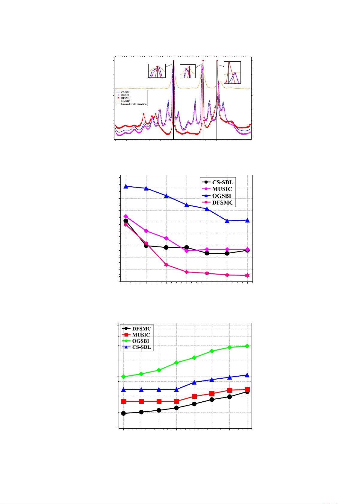
Article SBL-Based Direction Finding Method W ith Imperfect Array Peng Chen 1 , Zhimin Chen 2, *, Xuan Zhang 3 and Linxi Liu 3 1 State Key Laboratory of Millimeter W aves, Southeast Univerity , Nanjing 210096, China; chenpengseu@seu.edu.cn 2 School of Electronic and Information Engineering, Shanghai Dianji University , Shanghai 201306, China; 3 School of Information Science and Engineering, Southeast University , China; {zhangxuan, liulinxi}@seu.edu.cn * Correspondence: chenzm@sdju.edu.cn; T el.: +89-181-1631-4602 Academic Editor: name V ersion December 10, 2018 submitted to Electronics Abstract: The imperfect array degrades the direction finding performance. In this paper , we 1 investigate the direction finding pr oblem in uniform linear array (ULA) system with unknown 2 mutual coupling effect between antennas. By exploiting the target sparsity in the spatial domain, 3 sparse Bayesian learning (SBL)-based model is proposed and converts the direction finding problem 4 into a sparse r econstruction pr oblem. In the sparse-based model, the off-grid errors ar e intr oduced 5 by discretizing the dir ection area into grids. Therefor e, an off-grid SBL model with mutual coupling 6 vector is pr oposed to over come both the mutual coupling and the of f-grid ef fect. W ith the distribution 7 assumptions of unknown parameters including the noise variance, the of f-grid vector , the received 8 signals and the mutual coupling vector , a novel dir ection finding method based on SBL with unknown 9 mutual coupling effect named DFSMC is proposed, where an expectation-maximum (EM)-based 10 step is adopted by deriving the estimation expressions for all the unknown parameters theor etically . 11 Simulation results show that the proposed DFSMC method can outperform state-of-the-art direction 12 finding methods significantly in the array system with unknown mutual coupling effect. 13 Keywords: Compressed sensing; dir ection finding; sparse Bayesian learning; mutual coupling effect 14 1. Introduction 15 In the direction finding pr oblem, the traditional discrete Fourier transform (DFT)-based method 16 can only find one signal in one beam-width, so the resolution of such a method is too low to estimate 17 multiple signals. Therefore, the super-r esolution methods have been proposed including multiple 18 signal classification (MUSIC) method [ 1 , 2 ], Root-MUSIC method [ 3 ], and the estimating signal 19 parameters via rotational invariance techniques (ESPRIT) method [ 4 ]. Additionally , the subspace 20 methods have also been impr oved to estimate the corr elation signals, such as the spatial smoothing 21 MUSIC method [ 5 ]. However , the subspace methods only distinguish the noise and signal subspaces 22 and have not exploited additional characteristics of the received signals. 23 The compressed sensing (CS)-based methods have been proposed to estimate the dir ections by 24 exploiting the signal sparsity in the spatial domain [ 6 – 14 ]. Notably , the sparse Bayesian learning (SBL) 25 and the relevance vector machine (R VM) pr oposed in [ 15 ] can achieve better estimation performance in 26 the CS-based direction finding methods, where the dir ections are estimated by reconstr ucting the sparse 27 signals in the spatial domain with the corr esponding distribution assumptions of unknown parameters. 28 Consequently , the SBL-based CS method, named CS-SBL, is developed in [ 16 ] to reconstr uct the sparse 29 signals. However , in the CS-SBL method, the discrete grids are adopted to formulate the CS-based 30 Submitted to Electronics , pages 1 – 21 www .mdpi.com/journal/electronics V ersion December 10, 2018 submitted to Electr onics 2 of 21 system model, so the estimation performance is limited by the grid size. T o further improve the 31 estimation performance, dense grids can be adopted, but it will impr ove the computational complexity 32 in the sparse reconstr uction algorithm. 33 Additionally , the dense grids improve the correlation between the grids and decrease the 34 performance of sparse reconstr uction. The off-grid CS-based methods were proposed [ 17 , 18 ] to 35 overcome the grid problem in the CS-based model, such as the off-grid sparse Bayesian inference 36 (OGSBI) method proposed in [ 19 ]. In the off-grid CS-based system model, the ground-truth directi ons 37 are approximated by the T aylor expansion, so the performance of direction estimation can be impr oved 38 in the off-grid methods when the same grids are adopted. Moreover , by solving the roots of a 39 specific polynomial in an off-grid model, the Root-SBL method [ 20 ] was also proposed to decrease the 40 computational complexity of the SBL-based method. The grid evolution method was proposed in [ 21 ] 41 to refine the grids for the SBL-based method, and a dictionary learning algorithm is pr oposed in [ 22 ]. 42 In a practical direction finding problem, the imperfection of the antenna array will decr ease the 43 estimation performance, so the mutual coupling effect between antennas cannot be ignored [ 23 , 24 ]. The 44 direction finding methods wer e proposed in [ 25 – 27 ] to decrease the mutual coupling ef fect. However , 45 in the existing sparse-based methods, the unknown mutual coupling ef fect is not considered, especially 46 in a scenario with off-grid ef fect. 47 In this paper , a symmetric T oeplitz matrix [ 28 – 30 ] is used to describe the mutual coupling effect, 48 and a novel direction estimation method is proposed. W ith both the off-grid and the mutual coupling 49 effect, the dir ection finding problem is investigated. A novel system model is formulated to describe 50 both the off-grid and the mutual coupling ef fect. Then, by exploiting the signal sparsity in the spatial 51 domain, a novel direction finding method based on SBL with unknown mutual coupling ef fect, named 52 DFSMC, is proposed. Additionally , with the distribution assumptions, we theoretically derive the 53 estimation of all unknown parameters using the expectation-maximum (EM)-based method in DFSMC, 54 where the unknown parameters include the mutual coupling vector , the noise variance, the signals, the 55 off-grid vector , et al. Finally , the proposed DFSMC method is compar ed with the state-of-art methods 56 in the direction finding performance. T o summarize, we make the contributions as follows: 57 • The SBL-based system model with mutual coupling effect: W ith considering both the off-grid 58 and the unknown mutual coupling pr oblems, a novel system model is formulated and transforms 59 the direction finding pr oblems into a sparse reconstr uction problem. 60 • The DFSM method for direction finding estimation: W ith the distribution assumptions of 61 all unknown parameters, a novel SBL-based dir ection finding method with unknown mutual 62 coupling effect, named DFSMC, is proposed. DFSMC method estimates the dir ections via 63 updating all the unknown parameters alternatively and achieves better estimation performance 64 than the state-of-art methods. 65 • The theoretical estimation expressions for all unknown parameters: In the proposed DFSMC 66 method, the EM method is adopted to estimate all the unknown parameters including the 67 noise variance, the r eceived signals, the mutual coupling vector , and the off-grid vectors, et al. 68 W ith the distribution assumptions, we theoretically derive the expressions for all the unknown 69 parameters. 70 The remainder of this paper is organized as follows. The system model for direction finding with 71 unknown mutual coupling ef fect is formulated in Section 2 . The direction finding method based on 72 SBL is given in Section 3 . The simulation results are given in Section 4 . Finally , Section 5 concludes the 73 paper . 74 Notations: I N denotes an N × N identity matrix. E { · } denotes the expectation operation. 75 C N ( a , B ) denotes the complex Gaussian distribution with the mean being a and the covariance 76 matrix being B . k · k 2 , ⊗ , T r { · } , ( · ) ∗ , ( · ) T and ( · ) H denote the ` 2 norm, the Kronecker product, the 77 trace of a matrix, the conjugate, the matrix transpose and the Hermitian transpose, respectively . R{ a } 78 denotes the real part of complex value a . Additionally , for a vector a , [ a ] n denotes the n -th entry of a , 79 V ersion December 10, 2018 submitted to Electr onics 3 of 21 θ κ … θ κ θ κ θ κ d d s κ ( t ) s κ ( t ) s κ ( t ) s κ ( t ) Figure 1. The ULA system for direction finding. and diag { a } denotes a diagonal matrix with the diagonal entries from a . For a matrix A , A :, n denotes 80 the n -th column of A , and diag { A } denotes a vector with the entries from the diagonal entries of A . 81 2. ULA System for Direction Finding 82 W e consider the direction finding pr oblem in the uniform linear array (ULA) system , where N antennas are adopted and the inter-antenna element spacing is d . As shown in Fig. 1 , K unknown signals with dif ferent dir ections ( θ k , K = 0, 1, . . . , K − 1) are received by the ULA. Thus, the r eceived signals in the N antennas can be expressed as y ( t ) = K − 1 ∑ k = 0 C a ( θ k ) s k ( t ) + n ( t ) = C A s ( t ) + n ( t ) , (1) where the matrix C ∈ C N × N denotes the mutual coupling matrix, and the signals ar e collected into a vector s ( t ) , h s 0 ( t ) , s 1 ( t ) , . . . , s K − 1 ( t ) i T with the k -th signal being s k ( t ) . Then, the received signals in the ULA antennas can be expressed as y ( t ) , h y 0 ( t ) , y 1 ( t ) , . . . , y N − 1 ( t ) i T , and the zero-mean additive white Gaussian noise (A WGN) with the variance being σ 2 n is n ( t ) , h n 0 ( t ) , n 1 ( t ) , . . . , n N − 1 ( t ) i T . In this paper , we suppose that the noise variance σ 2 n is unknown. A ∈ C N × K denotes the steering matrix for the K signals, and can be expressed as A , h a ( θ 0 ) , a ( θ 1 ) , . . . , a ( θ K − 1 ) i , (2) where the steering vector for the k -th signal can be written as a ( θ k ) , h a 0 ( θ k ) , a 1 ( θ k ) , . . . , a N − 1 ( θ k ) i T , 83 a n ( θ k ) = e j 2 π nd λ sin θ k , and λ denotes the wavelength. 84 In this paper , we consider the dir ection finding problem with unknown mutual coupling ef fect between antennas, and the mutual coupling ef fect can be described usually by a symmetric T oeplitz matrix [ 29 ]. As expressed in ( 1 ), the mutual coupling matrix can be repr esented as C = 1 c 1 . . . c N − 1 c 1 1 . . . c N − 2 . . . . . . . . . . . . c N − 1 . . . c 1 1 , (3) where c n ( n = 1, 2, . . . , N − 1) denotes the mutual coupling coefficient between the n 1 -th antenna and 85 the n 2 -th antenna, and | n 1 − n 2 | = n . 86 V ersion December 10, 2018 submitted to Electr onics 4 of 21 The signal model in ( 1 ) is a contiiuous domain model, and after the uniform sampling, a discrete model can be obtained in a matrix form as Y = C AS + N , (4) where the sampling interval is T s , the number of the samples is M . Y ∈ C N × M , S ∈ C K × M and 87 N ∈ C N × M are expressed as Y = h y ( 0 ) , y ( T s ) , . . . , y (( M − 1 ) T s ) i , S = h s ( 0 ) , s ( T s ) , . . . , s (( M − 1 ) T s ) i , 88 N = h n ( 0 ) , n ( T s ) , . . . , n (( M − 1 ) T s ) i . T o simplify the notations, we define y m , y ( m T s ) , n m , n ( m T s ) 89 and s m , s ( m T s ) , so we have Y = h y 0 , y 1 , . . . , y M − 1 i , S = h s 0 , s 1 , . . . , s M − 1 i , N = h n 0 , n 1 , . . . , n M − 1 i . 90 However , the system model in ( 4 ) is hard to solve directly with the unknown mutual coupling matrix C , so we try to express the matrix C in a vector form. The mutual coupling matrix in ( 3 ) can be described alternatively by a vector c as C = T oeplitz { c } , where c , h 1, c 1 , . . . , c N − 1 i T is the first column of C , and T oeplitz {· } denotes the T oeplitz transformation. Therefor e, after the simplification, the received signals during the m -th sampling interval in ( 4 ) can be rewritten as y m = C A s m + n m = Q ( s m ⊗ c ) + n m , (5) where the mutual coupling effect is expressed by a vector c , and we use a matrix Q ∈ C N × K N to 91 rearrange the steering matrix A . 92 According to the lemma in [ 29 , 31 , 32 ], the matrix Q in ( 5 ) can be obtained as Q , h Q ( θ 0 ) , Q ( θ 1 ) , . . . , Q ( θ K − 1 ) i . (6) The k -th sub-matrix Q ( θ k ) ∈ C N × N is Q ( θ k ) = Q 1 ( θ k ) + Q 2 ( θ k ) , where Q 1 ( θ k ) and Q 2 ( θ k ) respectively are Q 1 ( θ k ) , a 0 ( θ k ) a 1 ( θ k ) . . . a N − 1 ( θ k ) a 1 ( θ k ) a 2 ( θ k ) . . . 0 . . . . . . . . . . . . a N − 2 ( θ k ) a N − 1 ( θ k ) . . . 0 a N − 1 ( θ k ) 0 . . . 0 , (7) Q 2 ( θ k ) , 0 0 . . . 0 0 0 a 0 ( θ k ) . . . 0 0 . . . . . . . . . . . . . . . 0 a N − 3 ( θ k ) . . . a 0 ( θ k ) 0 0 a N − 2 ( θ k ) . . . a 1 ( θ k ) a 0 ( θ k ) . (8) Therefor e, by collecting the M samples into a matrix, the received signals in ( 4 ) can be finally rewritten as Y = Q ( S ⊗ c ) + N . (9) In this paper , we will propose a high resolution method to estimate the directions ( θ 0 , θ 1 ,. . . , θ K − 1 ) 93 from the received signal matrix Y , where the signal matrix S , the mutual coupling vector c and the 94 noise variance σ 2 n are all unknown. 95 V ersion December 10, 2018 submitted to Electr onics 5 of 21 … … … … ! 0 0 0 0 ! S 0,0 ! S 0,1 S 0,2 S 0,M-1 0 0 0 0 ! S k,0 ! S k,1 S k,2 S k,M-1 0 0 0 0 ! … … … … ! The 0 -th signal The k -th signal X= The ( M-1) -th samples Figure 2. The structure of sparse matrix X . 3. Direction Finding Method Based on Sparse Bayesian Learning 96 In this section, we propose a novel SBL-based method to estimate the directions ( named D irection 97 F inding based on S BL with M utual C oupling effect, DFSMC ). The sparse model will be established 98 first, and the DFSMC will be proposed with the distribution assumptions of unknown parameters. 99 3.1. Sparse-Based Signal Model 100 Since the received signals are sparse in the spatial domain, we propose a sparse-based model to estimate the directions with unknown mutual coupling effect. In the sparse-based model, the dictionary matrix must be established first, so an over-complete dictionary matrix can be formulated by discretizing the signal dir ection uniformly in the spatial domain D , h Q ( ζ 0 ) , Q ( ζ 1 ) , . . . , Q ( ζ U − 1 ) i ∈ C N × U N , (10) where ζ u denotes the u -th discretized direction ( u = 0, 1, . . . , U − 1), U denotes the number of 101 discretized directions, the grid size is defined as δ , | ζ u + 1 − ζ u | , and we use a vector to contain 102 all the discretized dir ections ζ , h ζ 0 , ζ 1 , . . . , ζ U − 1 i . 103 W ith the discretized directions and the system model in ( 9 ), a sparse-based on-grid direction finding model can be expressed as Y = D ( X ⊗ c ) + N , (11) where X is a sparse matrix X , h x 0 , x 1 , . . . , x M − 1 i ∈ C U × M . (12) The structure of sparse matrix X is shown in Fig. 2 , and the sparse vectors ( x 0 , x 1 , . . . , x M − 1 ) have the same support sets. When the direction of the k -th received signal θ k is equal to the u k -th discretized direction ζ u k , we have X u k , m = S k , m , so the u -th row and m -th column of X is X u , m = ( S k , m , u = u k 0, otherwise . (13) V ersion December 10, 2018 submitted to Electr onics 6 of 21 ζ 0 ζ 5 ζ 1 ζ 4 ζ 3 ζ 2 ζ 8 ζ 7 ζ 6 s k ( t ) θ k θ k — ζ 3 Figure 3. The off-grid approximation for dir ection. The sparse-based model in ( 12 ) assumes that the directions of r eceived signals are exactly on the discretized grids. However , in the practical direction finding system, when the dir ection θ k is not on the discretized grids, the direction θ k can be repr esented by ζ u k , which is a grid nearest to θ k . Thus, the corresponding matrix Q ( θ k ) in ( 2 ) can be approximated by Q ( θ k ) ≈ Q ( ζ u k ) + ( θ k − ζ u k ) Ω ( ζ u k ) , (14) where the first-order derivative is defined as Ω ( ζ u k ) , ∂ Q ( ζ ) ∂ζ ζ = ζ u k . For example, as shown in Fig. 3 , 104 the direction of signal s k ( t ) is θ k , and the nearest grid is ζ 3 . Thus, the corresponding matrix Q ( θ k ) in 105 ( 14 ) can be written as Q ( θ k ) ≈ Q ( ζ 3 ) + ( θ k − ζ 3 ) Ω ( ζ 3 ) . 106 Therefor e, with the approximation in ( 14 ), the received signal in ( 9 ) can be approximated by a sparse-based off-grid model Y ≈ Ψ ( ν ) ( X ⊗ c ) + N , (15) where Ψ ( ν ) , D + Ξ ( diag { ν } ⊗ I N ) , Ξ , h Ξ 0 , Ξ 1 , . . . , Ξ U − 1 i , and the u -th submatrix of Ξ is denoted as Ξ u , Ω ( ζ u ) . Additionally , a vector ν ∈ R U × 1 is used to r epresent the of f-grid directions, and the u -th entry is ν u = ( θ k − ζ u k , u = u k 0, otherwise . (16) Finally , an off-grid sparse-based model is formulated for the dir ection finding problem in ( 15 ). W e 107 will estimate the directions by reconstructing the sparse matrix X . The positions of non-zero entries in 108 X indicate the directions of r eceived signals. Simultaneously , the unknown parameters including the 109 mutual coupling vector c , the noise variance σ 2 n and the off-grid vector ν will also be estimated. 110 3.2. Distribution Assumptions 111 In the proposed DFSMC method, the sparse Bayesian learning theory is adopted, and the method 112 is established based on the distribution assumptions of all the unknown parameters. W e assume that 113 the unknown parameters follow the following distributions: 114 • Noise N : Gaussian distribution; 115 • The precision of noise variance α n : Gamma distribution; 116 • Sparse matrix X : Gaussian distribution; 117 • The precision of signal variance ι : Gamma distribution; 118 • Mutual coupling vector c : Gaussian distribution; 119 • The precision of mutual coupling variance ϑ : Gamma distribution; 120 • Off-grid vector ν : Uniform distribution. 121 V ersion December 10, 2018 submitted to Electr onics 7 of 21 Received signal Y Sparse matrix X Mutual coupling vector c Off-grid vector ν Hyperparameter a Hyperparameter c Hyperparameter d Hyperparameter b Hyperparameter e Hyperparameter f Signal variance pr ecision ι Mutual coupling variance pr ecision ν Grid space δ Noise N Noise variance pr ecision α n Figure 4. Graphical model of sparse bayesian learning for direction estimation. The relationships between all the unknown parameters are given in Fig. 4 , and we will describe the 122 distributions more clear in the following contents. 123 3.2.1. The distribution of noise 124 When the received signals are independent between differ ent samples, with the assumption of circular symmetric white Gaussian noise, the distribution of noise can be expr essed as p ( N | σ 2 n ) = M − 1 ∏ m = 0 C N ( n m | 0 N × 1 , σ 2 n I N ) , (17) where σ 2 n denotes the noise variance, and the complex Gaussian distribution with the mean being µ and the covariance matrix being Σ is expressed as C N ( x | µ , Σ ) = 1 π N det ( Σ ) e − ( x − µ ) H Σ − 1 ( x − µ ) . (18) 3.2.2. The distribution of noise variance σ 2 n 125 In this paper , the noise variance is unknown. Since the Gamma distribution is a conjugate prior of Gaussian distribution, the posterior distribution also follows a Gamma distribution. Therefor e, using the Gamma distribution can simplify the following analysis. W ith the unknown noise variance σ 2 n , we use a Gamma distribution to describe the precision of noise variance α n , σ − 2 n , and we have the following Gamma distribution p ( α n ) = g ( α n ; a , b ) , (19) where a and b are the hyperparameters for α n , and g ( α n ; a , b ) , Γ − 1 ( a ) b a α a − 1 n e − b α n , Γ ( a ) , 126 R ∞ 0 x a − 1 e − x d x . 127 V ersion December 10, 2018 submitted to Electr onics 8 of 21 3.2.3. The distribution of sparse matrix 128 W ith the independent received signals S among samples, we can assume that the sparse matrix X follows a zero-mean Gaussian distribution p ( X | Λ x ) = M − 1 ∏ m = 0 C N ( x m | 0 U × 1 , Λ x ) , (20) where the covariance matrix Λ x ∈ R U × U is a diagonal matrix with the u -th diagonal entry being σ 2 x, u . 129 3.2.4. The distribution of signal variance 130 Similarity , with the unknown signal variance Λ x , we define the precision vector ι , h ι 0 , ι 1 , . . . , ι U − 1 i T , where ι u , σ − 2 x, u , so ι can be expressed by a Gamma prior p ( ι ; c , d ) = U − 1 ∏ u = 0 g ( ι u ; c , d ) , (21) where c and d are the hyperparmaters for ι . 131 3.2.5. The distribution of mutual coupling vector 132 W ith the unknown mutual coupling vector , when the mutual coupling coefficients are independent between antennas, the distribution of mutual coupling vector c can be expressed as a Gaussian distribution p ( c | Λ c ) = N − 1 ∏ n = 0 C N ( c n | 0, Λ c ) , (22) where the covariance matrix Λ c ∈ R N × N is a diagonal matrix with the n -th diagonal entry being σ 2 c, n . 133 3.2.6. The distribution of mutual coupling variance 134 By defining the pr ecisions ϑ , h ϑ 0 , ϑ 1 , . . . , ϑ N − 1 i T ( ϑ n , σ − 2 c, n ), we use a Gamma distribution to describe the distribution of ϑ p ( ϑ ; e , f ) = N − 1 ∏ n = 0 g ( ϑ n ; e , f ) , (23) where both e and f are the hyperparameters of ϑ . 135 3.2.7. The distribution of off-grid vector 136 W e can assume that the off-grid vector ν follows a uniform distribution, and the distribution of ν u can be expressed as p ( ν u ; δ ) = U ν u − 1 2 δ , 1 2 δ , (24) where the uniform distribution is defined as U x ([ a , b ]) , ( 1 b − a , a ≤ x ≤ b 0, otherwise . (25) V ersion December 10, 2018 submitted to Electr onics 9 of 21 3.3. DFSMC method 137 W ith the distribution assumptions of unknown parameters, a novel direction finding method 138 based on the SBL is proposed with the unknown mutual coupling effect, named DFSMC. In the 139 SBL-based method, the posterior probabilities for all the unknown parameters ar e theor etically derived. 140 T o estimate the directions, we formulate the following problem to maximize the posterior probability ˆ ℘ = arg max ℘ p ( ℘ | Y ) , (26) where a set ℘ , X , ν , c , σ 2 n , ι , ϑ is used to contain all the unknown parameters. However , the pr oblem ( 26 ) is too complex and cannot be solved directly . The expectation maximum (EM)-based method is used to realize the proposed DFSMC method. Additionally , with the received signal Y , the joint distribution with unknown parameters can be expressed as p ( Y , ℘ ) = p ( Y | ℘ ) p ( X | ι ) p ( c | ϑ ) p ( α n ) p ( ι ) p ( ϑ ) p ( ν ) . (27) The details to estimate all unknown parameters are given as follows. 141 3.3.1. The sparse matrix 142 Given the received signal Y and the parameters ( ℘ \ X ) excepting X , the the posterior of X can be expressed as p ( X | Y , ν , c , α n , ι , ϑ ) = p ( Y | ℘ ) p ( X | ι ) p ( Y | ν , c , α n , ι , ϑ ) ∝ p ( Y | ℘ ) p ( X | ι ) , (28) where both p ( Y | ℘ ) and p ( X | ι ) follow Gaussian distributions, and can be calculated as p ( Y | ℘ ) = M − 1 ∏ m = 0 α N n π N e − α n k y m − Ψ ( ν )( x m ⊗ c ) k 2 2 , (29) p ( X | ι ) = M − 1 ∏ m = 0 U − 1 ∏ u = 0 ι u ! 1 π U e − x H m diag { ι } x m . (30) Therefor e, the posterior of X is also a Gaussian function p ( X | Y , ν , c , α n , ι , ϑ ) = M − 1 ∏ m = 0 C N ( x m | µ m , Σ X ) , (31) where the mean µ m and covariance matrix Σ X are obtained fr om ( 29 ) and ( 30 ) as µ m = α H n Σ H X T H ( ν , c ) y m , (32) Σ X = h α n T H ( ν , c ) T ( ν , c ) + diag { ι } i − 1 , (33) and we define the following function T ( ν , c ) , Ψ ( ν )( I U ⊗ c ) . (34) Additionally , to simplify the notations, the u -th entry of µ m is denoted as µ u , m , and we can collect all 143 the mean µ m as a matrix µ , h µ 0 , µ 1 , . . . , µ M − 1 i . 144 V ersion December 10, 2018 submitted to Electr onics 10 of 21 T o estimate the other unknown parameters ℘ \ X , with ( 27 ), we can formulate the following likelihood function L ( ν , c , α n , ι , ϑ ) = E ln p ( Y | ℘ ) p ( X | ι ) p ( c | ϑ ) p ( α n ) p ( ι ) p ( ϑ ) p ( ν ) . (35) where we just use E {· } to represent E X | Y , ν , α n , ι , ϑ {· } . Thus, the EM-based method can be used to estimate 145 ℘ \ X , and the details are given in the following contents. Additionally , the derivatives for the complex 146 vector and matrix are given as the following lemma. 147 Lemma 1. With both the complex vectors ( u ∈ C P × 1 , v ∈ C P × 1 ) and the complex matrix A ∈ C M × P being the function of a complex vector x ∈ C N × 1 , the following derivations can be obtained ∂ u H v ∂ x = v T ∂ ( u ∗ ) ∂ x + u H ∂ v ∂ x , (36) ∂ Au ∂ x = h ∂ A ∂ x 0 u + A ∂ u ∂ x 0 , . . . , ∂ A ∂ x n u + A ∂ u ∂ x n , . . . i . (37) Proof. See: Appendix A . 148 3.3.2. The mutual coupling vector 149 Ignoring terms independent thereof in L ( ν , c , α n , ι , ϑ ) , we can obtain the following likelihood function for the mutual coupling vector c L ( c ) = E { ln p ( Y | X , ν , c , α n ) p ( c | ϑ ) } = E ( ln M − 1 ∏ m = 0 C N ( y m | Ψ ( ν ) ( x m ⊗ c ) , α − 1 n I N ) ) + ln N − 1 ∏ n = 0 C N ( c n | 0, ϑ − 1 n ) (38) ∝ − α n M G 1 ( c , ν ) − M − 1 ∑ m = 0 α n G 2, m ( c , ν ) − G 3 ( c ) , where we have E { ln p ( Y | X , ν , c , α n ) } = M N ln α n π − α n M G 1 ( c , ν ) − M − 1 ∑ m = 0 α n G 2, m ( c , ν ) , (39) and G 1 ( c , ν ) , T r T H ( ν , c ) T ( ν , c ) Σ X , G 2, m ( c , ν ) , k y m − Ψ ( ν )( µ m ⊗ c ) k 2 2 , G 3 ( c ) , ∑ N − 1 n = 0 ϑ n | c n | 2 . 150 T o estimate the mutual coupling vector c , we can maximize the likelihood function L ( c ) , and we have ˆ c = arg max c L ( c ) . (40) Therefor e, by setting ∂ L ( c ) ∂ c = 0 , the mutual coupling vector can be obtained. W e can calculate ∂ L ( c ) ∂ c = − α n M ∂ G 1 ( c , ν ) ∂ c − M − 1 ∑ m = 0 α n ∂ G 2, m ( c , ν ) ∂ c − ∂ G 3 ( c ) ∂ c . (41) In ( 41 ), ∂ G 1 ( c , ν ) ∂ c , ∂ G 2, m ( c , ν ) ∂ c and ∂ G 3 ( c ) ∂ c can be calculated as follows. 151 • For ∂ G 1 ( c , ν ) ∂ c : W ith the derivations of complex vector and matrix in Appendix A , ∂ G 1 ( c , ν ) ∂ c is a row vector , and the n -th entry can be calculated as ∂ G 1 ( c , ν ) ∂ c n = T r ∂ T H ( ν , c ) T ( ν , c ) Σ X ∂ c n . (42) V ersion December 10, 2018 submitted to Electr onics 11 of 21 Additionally , we can calculate ∂ T H ( ν , c ) T ( ν , c ) Σ X ∂ c n = ∂ ( I U ⊗ c ) H ∂ c n Ψ H ( ν ) T ( ν , c ) Σ X ] + T H ( ν , c ) Ψ ( ν ) ∂ ( I U ⊗ c ) ∂ c n Σ X = T H ( ν , c ) Ψ ( ν ) I U ⊗ ∂ c ∂ c n Σ X = T H ( ν , c ) T ( ν , e N n ) Σ X , (43) where e N n is a N × 1 vector with the n -th entry being 1 and other entries being 0. Therefor e, the the n -th entry in ( 42 ) can be simplified as ∂ G 1 ( c , ν ) ∂ c n = c H U − 1 ∑ p = 0 U − 1 ∑ k = 0 Ψ H p ( ν ) Ψ k ( ν ) Σ X, k , p ! e N n , (44) and we finally have the derivation of G 1 ( c , ν ) as ∂ G 1 ( c , ν ) ∂ c = c H U − 1 ∑ p = 0 U − 1 ∑ k = 0 Ψ H p ( ν ) Ψ k ( ν ) Σ X, k , p ! . • ∂ G 2, m ( c , ν ) ∂ c can be simplified as ∂ G 2, m ( c , ν ) ∂ c = − [ y m − Ψ ( ν )( µ m ⊗ c )] H Ψ ( ν ) ∂ µ m ⊗ c ∂ c = − [ y m − Ψ ( ν )( µ m ⊗ c )] H Ψ ( ν ) ( µ m ⊗ I N ) . (45) • ∂ G 3 ( c ) ∂ c can be simplified as ∂ G 3 ( c ) ∂ c = c H diag { ϑ } . 152 Therefor e, with ( 41 ), the mutual coupling vector can be finally estimated as ˆ c = H − 1 z , (46) where H = M − 1 ∑ m = 0 α n P H ( ν , µ m ) P ( ν , µ m ) + α n M U − 1 ∑ p = 0 U − 1 ∑ k = 0 Ψ H p ( ν ) Ψ k ( ν ) Σ X, k , p ! H + diag { ϑ } , (47) z = M − 1 ∑ m = 0 α n P H ( ν , µ m ) y m , (48) and we define P ( ν , µ m ) , Ψ ( ν )( µ m ⊗ I N ) . 153 3.3.3. For the precision of signal variance 154 Ignoring terms independent thereof in L ( ν , c , α n , ι , ϑ ) , we can obtain the likelihood function of ι as L ( ι ) = E { ln p ( X | ι ) p ( ι ) } = E ( ln M − 1 ∏ m = 0 C N ( x m | 0 U × 1 , Λ x ) ) + ln U − 1 ∏ u = 0 g ( ι u ; c , d ) . (49) Then, the precision of signal variance can be estimated by ˆ ι = arg max ι L ( ι ) . 155 By setting ∂ L ( ι ) ∂ ι = 0, the u -th entry of ι can be obtained as ˆ ι u = M + c − 1 d + M Σ X, u , u + ∑ M − 1 m = 0 | µ u , m | 2 . (50) V ersion December 10, 2018 submitted to Electr onics 12 of 21 In the iterative algorithm, ( 50 ) can be rewritten as ˆ ι i + 1 u ≈ M − 1 − ˆ ι i u ∑ M − 1 m = 0 | µ u , m | 2 d + M Σ X, u , u , (51) where ˆ ι i + 1 u and ˆ ι i u are the esitmated r esults at the ( i + 1 ) -th and the i -th iterations, respectively . 156 3.3.4. For α n 157 Ignoring terms independent thereof in L ( ν , c , α n , ι , ϑ ) , we can obtain the likelihood function L ( α n ) = E { ln p ( Y | X , ν , c , α n ) p ( α n ) } = E ( ln M − 1 ∏ m = 0 C N y m | Ψ ( ν ) ( x m ⊗ c ) , σ 2 n I ) + ln g ( α n ; a , b ) . (52) The precision of noise variance can be estimated by ˆ α n = arg max α n L ( α n ) . (53) By setting ∂ L ( α n ) ∂α n = 0, we can obtain ˆ α n = M N + a − 1 M G 1 ( c , ν ) + ∑ M − 1 m = 0 G 2, m ( c , ν ) + b . (54) In the iterative algorithm, ( 54 ) can be rewritten as ˆ α i + 1 n ≈ M N − 1 − ˆ α i n ∑ M − 1 m = 0 G 2, m ( c , ν ) M G 1 ( c , ν ) + b ., (55) where ˆ α i + 1 n and ˆ α i n are the esitmated r esults at the ( i + 1 ) -th and the i -th iterations, respectively . 158 3.3.5. For the precision of mutual coupling variance 159 Ignoring terms independent thereof in L ( ν , c , α n , ι , ϑ ) , we can obtain the likelihood function L ( ϑ ) = E { ln p ( c | ϑ ) p ( ϑ ) } = E ( ln N − 1 ∏ n = 0 C N ( c n | 0, ϑ − 1 n ) ) + ln N − 1 ∏ n = 0 g ( ϑ n ; e , f ) . (56) The precision of mutual coupling variance can be estimated by ˆ ϑ = arg max ϑ L ( ϑ ) . 160 By setting ∂ L ( ϑ ) ∂ ϑ = 0 , we can obtain the n -th entry of ϑ as ˆ ϑ n ≈ 1 f + c H n c n . (57) 161 3.3.6. For the off-grid vector 162 Ignoring terms independent thereof in L ( ν , c , α n , ι , ϑ ) , we can obtain the likelihood function L ( ν ) = E { ln p ( Y | X , ν , c , α n ) p ( ν ) } ∝ − M G 1 ( c , ν ) − M − 1 ∑ m = 0 G 2, m ( c , ν ) . (58) V ersion December 10, 2018 submitted to Electr onics 13 of 21 The off-grid vector can be estimated by ˆ ν = arg max ν L ( ν ) . (59) Then, ∂ G 1 ( c , ν ) ∂ ν ∈ R 1 × U is a row vector , and the u -th entry is ∂ G 1 ( c , ν ) ∂ ν u = T r ∂ T H ( ν , c ) T ( ν , c ) Σ X ∂ν u = T r nh 0 , T H ( ν , c ) Ξ u c , 0 i Σ X o + T r h 0 , T H ( ν , c ) Ξ u c , 0 i H Σ X = 2 R ( U − 1 ∑ m = 0 c H Ψ H m ( ν ) Ξ u c Σ X, u , m ) = 2 R h T H ( ν , c ) Ξ u c i H Σ X,:, u . (60) ∂ G 1 ( c , ν ) ∂ ν can be simplified as ∂ G 1 ( c , ν ) ∂ ν = 2 R diag n Σ X T H ( ν , c ) Ξ ( I U ⊗ c ) o T . (61) Additionally , ∂ G 2, m ( c , ν ) ∂ ν can be obtained as ∂ G 2, m ( c , ν ) ∂ ν = − 2 R [ y m − Ψ ( ν )( µ m ⊗ c )] H ∂ Ψ ( ν )( µ m ⊗ c ) ∂ ν (62) = − 2 R n [ y m − Ψ ( ν )( µ m ⊗ c )] H Ξ ( diag { µ m } ⊗ c ) o . Therefor e, with ∂ L ( ν ) ∂ν u = 0, we can obtain ˆ ν = G − 1 z , (63) where the entry of the u -th row in G ∈ R U × U is G u ,: = R n M c H Ξ H u Ξ ( diag { Σ X,:, u } ⊗ c ) o + M − 1 ∑ m = 0 R n µ m , u c T Ξ T u Ξ * ( I U ⊗ c ∗ ) diag ∗ { µ m } o , (64) and the u -th entry of z ∈ R U × 1 is z u = M − 1 ∑ m = 0 R n [ y m − D ( µ m ⊗ c )] H Ξ u µ m , u c o − M R n c H Ξ H u D ( I U ⊗ c ) Σ X,:, u o . (65) In Algorithm 1 , we show the details of the proposed DFSMC method for the direction finding 163 with the unknown mutual coupling effect. In the proposed DFSMC algorithm, after the iterations, 164 we can obtain the spatial spectrum P X of the sparse matrix X from the received signal Y . Then, by 165 searching all the values of P X , the corresponding peak values can be found. By selecting positions of 166 peak values corresponding to the K maximum values, we can estimate the directions with ζ + ν . 167 4. Simulation Results 168 Extensive simulation results have been conducted. All experiments are conducted in Matlab R2017b on a PC with a 2.9 GHz Intel Core i5 and 8 GB of RAM, and Matlab codes have been V ersion December 10, 2018 submitted to Electr onics 14 of 21 Algorithm 1 DFSMC algorithm for direction finding with the unknown mutual coupling ef fect 1: Input: received signal Y , the number of samples M , the numbers of iterations N 1 , N 2 and N 3 dictionary matrix D , the first order derivative of dictionary matrix Ξ . Usually , we have N 1 = 10 3 , N 2 = 300, N 3 = 50, b = d = f = 10 − 3 , and a = c = e = 1 + b . 2: Initialization: i iter = 1, s method = 0, i method = 1, ˆ c = ˆ ϑ = [ 1, 0 1 × ( N − 1 ) ] T , and ˆ ν = 0 U × 1 . 3: Ψ ( ˆ ν ) ← D + Ξ ( diag { ˆ ν } ⊗ I N ) . 4: while i iter ≤ N 1 do 5: Obtain T ( ν , c ) fr om ( 34 ). 6: Obtain the mean µ m ( m = 0, 1, . . . , M − 1) and covariance matrix Σ X from ( 32 ) and ( 33 ), respectively . 7: Update the precision of noise variance ˆ α n from ( 55 ). 8: Update the precision of signal variance ˆ ι from ( 51 ). 9: Obtain the spatial spectrum P X = 1 ˆ ι 0 , 1 ˆ ι 1 , . . . , 1 ˆ ι N − 1 T . 10: if i iter ≥ N 2 and s method = 1 then 11: i method ← i method + 1. 12: if i method = N 3 then 13: i method ← 1. 14: s method ← 0. 15: end if 16: Update the of f-grid vector ˆ ν from ( 63 ). 17: Ψ ( ˆ ν ) ← D + Ξ ( diag { ˆ ν } ⊗ I N ) . 18: end if 19: if i iter ≥ N 2 and s method = 0 then 20: i method ← i method + 1. 21: if i method = N 3 then 22: i method ← 1. 23: s method ← 1. 24: end if 25: Update the pr ecision of mutual coupling variance ˆ ϑ from ( 57 ). 26: Update the mutual coupling vector ˆ c from ( 46 ). 27: end if 28: i iter ← i iter + 1. 29: end while 30: Output: the spatial spectrum P X , and the directions ( ζ + ν ) . V ersion December 10, 2018 submitted to Electr onics 15 of 21 rrdg 313x 314 314x 31I 31Ix 31a 31ax 31s 3 I43 I s43 I 643 I 43 I 43 a Figure 5. The estimation error with iterations ( α c = − 8 dB). aaru B14 B24 B34 B04 4 aru Bo4 B14 B34 4 34 14 o4 Figure 6. The spatial spectrum for direction estimation ( α c = − 8 dB). rrdg sI2 2 s x2s x 62s x 32s x 2s x 2s 4 Figure 7. The estimation error with iterations ( α c = − 5 dB). V ersion December 10, 2018 submitted to Electr onics 16 of 21 aaru B14 B24 B34 B04 4 aru Bo4 BD4 B14 B24 B34 B04 4 04 34 24 14 D4 o4 Figure 8. The spatial spectrum for direction estimation ( α c = − 5 dB). S0. 97B 97- 972 97 97 97 97 1 171 S0. 6N 9 N - 19 Figure 9. The direction estimation performance with differ ent SNRs. S0. olp p po SSSSSS0. apw apf api apo as aw af ai Figure 10. The direction estimation performance with differ ent mutual coupling effect. V ersion December 10, 2018 submitted to Electr onics 17 of 21 T able 1. Simulation Parameters Parameter V alue The signal-to-noise ratio (SNR) 20 dB The number of samples M 100 The number of antennas N 20 The number of signals K 3 The space between antennas d 0.5 wavelength The grid space δ 1 ◦ The direction range [ − 60 ◦ , 60 ◦ ] The hyperparameters b , d , f 10 − 3 N 1 in Algorithm 1 N 1 = 10 3 N 2 in Algorithm 1 N 2 = 300 N 3 in Algorithm 1 N 3 = 50 T able 2. Estimated directions ( α c = − 8 dB) Methods Signal 1 Signal 2 Signal 3 Ground-truth directions − 8.268 ◦ 18.128 ◦ 30.428 ◦ OGSBI − 8.267 ◦ 17.69 ◦ 30.02 ◦ CS-SBL − 8 ◦ 18 ◦ 30 ◦ MUSIC − 8 ◦ 18 ◦ 30 ◦ DFSMC − 8.254 ◦ 18.13 ◦ 30.27 ◦ T able 3. Estimated directions ( α c = − 5 dB) Methods Signal 1 Signal 2 Signal 3 Ground-truth directions − 8.268 ◦ 18.128 ◦ 30.428 ◦ OGSBI − 8.222 ◦ 17.29 ◦ 31.99 ◦ CS-SBL − 8 ◦ 17 ◦ 32 ◦ MUSIC − 8 ◦ 18 ◦ 33 ◦ DFSMC − 8.260 ◦ 18.11 ◦ 30.66 ◦ made available online at https://drive.google.com/drive/folders/1XwzbNtHXfjT rN4- wylAhGI- CwIY3u3K1 . The mutual coupling effect can be generated by the following expression c n = ( 1 + ξ c ) e j φ c 10 α c ( 1 + 0.5 n ) 20 , n < 5 0, otherwise , (66) where ξ c ∼ U ξ c ([ − 0.05, 0.05 ]) , φ c ∼ U φ c ([ 0, 2 π ]) , and we use the parameter α c in dB to measure the 169 mutual coupling ef fect between adjacent antennas. Additionally , we use the independent Gaussian 170 distribution to generate the received signals, and for the m -th sample in the n -th antenna, we have 171 s n , m ∼ C N √ 2 e j π 2 , 1 . 172 In this paper , to compare with the state-of-art direction estimation methods, we compare the 173 proposed DFSMC method with the following algorithms: 174 V ersion December 10, 2018 submitted to Electr onics 18 of 21 • CS-SBL 1 , the Bayesian compressive sensing method pr oposed in [ 16 ]. 175 • OGSBI 2 , the off-grid sparse Bayesian infer ence method proposed in [ 19 ]. 176 • MUSIC, the multiple signal classification method [ 1 , 2 ]. 177 W ith the simulation parameters in T able 1 and the the mutual coupling between adjacent antennas 178 being α c = − 8 dB, the spatial spectrum is given in Fig. 6 , where the proposed DFSMC is compar ed 179 with MUSIC, CS-SBL and OGSBI methods. The estimated directions for K = 3 signals are given 180 in T able 2 . Additionally , the iteration processes of DFSMC, CS-SBL, and OGSBI methods are also 181 given in Fig. 5 . W ith both the mutual coupling effect and off-grid, the proposed DFSMC method is 182 advantageous in this scenario. 183 As shown in Fig. 5 , in the first 300 iterations, DFSMC method only updates the parameters µ m , Σ X 184 and ι . Then, during the 301 to 350 iterations, the mutual coupling parameters c and ϑ are updated. For 185 the next 50 iterations, the of f-grid parameter ν is updated. W ith repeating the 50 iterations to update 186 the mutual coupling parameters and the off-grid parameter , the direction error can be decreased. 187 Moreover , as shown in Fig. 5 , when only the mutual coupling parameters ar e updated, the direction 188 estimation performance can be not improved with the corr ect estimated directions. However , for the 189 next off-grid estimation, the better performance can be achieved with the updated mutual coupling 190 parameters. 191 The estimated spatial spectrum is shown in Fig. 6 . It can be seen that the positions of peak spectrum are closer to the gr ound-truth directions using the DFSMC method than the OGSBI, CS-SBL and MUSIC methods. The corresponding estimated dir ections are given in T able 2 . When we use the following expression to measur e the estimation performance e 1 = r 1 K k ˆ θ − θ k 2 2 , (67) where ˆ θ denotes the estimated directions. Then, the estimation errors (in deg) of DFSMC, OGSBI, 192 CS-SBL and MUSIC methods can be obtained as 0.092 ◦ , 0.346 ◦ , 0.301 ◦ and 0.301 ◦ , respectively . 193 Therefor e, since the mutual coupling effect is estimated in the proposed DFSMC method, the direction 194 estimation performance is much better than the existing methods including OGSBI, CS-SBL and 195 MUSIC. 196 When the mutual coupling ef fect increases from α c = − 8 dB to α c = − 5 dB, the corr esponding 197 iteration processes and the spatial spectrums of DFSMC, CS-SBL, OGSBI and MUSIC methods are 198 given in Fig. 7 and Fig. 8 . The estimated directions are given inT able 3 , and the estimation errors 199 (in deg) of DFSMC, OGSBI, CS-SBL and MUSIC methods can be obtained as 0.134 ◦ , 1.024 ◦ , 1.128 ◦ 200 and 1.495 ◦ . Compared with the direction estimation performance in the scenario α c = − 8 dB, the 201 performance in the scenario α c = − 5 dB decreases for all the methods, so the mutual coupling ef fect 202 has a gr eat effect on the direction estimation performance. However , the pr oposed DFSMC method 203 can also achieve much better performance than existing methods. 204 W ith the 100 trails, the dir ection estimation performance with dif ferent SNRs is given in Fig. 9 , where we use the following root-mean-square error (RMSE) expression to measure the estimation performance e 2 = v u u t 1 K P P − 1 ∑ p = 0 k ˆ θ p − θ p k 2 2 , (68) 1 The MA TLAB code was downloaded at http://people.ee.duke.edu/~lcarin/BCS.html 2 The MA TLAB code was downloaded at https://sites.google.com/site/zaiyang0248/publication V ersion December 10, 2018 submitted to Electr onics 19 of 21 where P denote the number of trails, θ p denotes the directions in the p -th trail, and ˆ θ p denotes the 205 estimated directions in the p -th trail. As shown in Fig. 9 , the proposed DFSMC method achieves 206 the best estimation performance when the SNR of received signals is greater than 0 dB. Almost the 207 same estimation performance is achieved by the MUSIC and CS-SBL method. However , with the 208 mutual coupling effect, the dir ection grids usually cannot be estimated corr ectly , so the further off-grid 209 optimization in OGSBI cannot improve the estimation performance. Fig. 9 indicates that our proposed 210 DFSMC method is very advantageous in the cases when the SNR of received signals is lar ge. 211 W ith different mutual coupling effects between antennas, we show the simulation results in 212 Fig. 10 , where the mutual coupling effect α c between adjacent antennas is fr om − 16 dB to − 2 dB. Since 213 the proposed DFSMC method estimates the mutual coupling vector c iteratively , and DFSMC achieves 214 the best estimation performance among the existing methods including CS-SBL, OGSBI, and MUSIC. 215 It can be seen that with optimizing the off-grid and the mutual coupling vector , the performance of 216 direction estimation can be improved by estimating the sparse signals in the continue domain using 217 the DFSMC method. The computational complexity of the proposed algorithm mainly depends on 218 step 6 , step 16 and step 26 . The computational complexity of step 6 , step 16 and step 26 can be obtained 219 as O ( M U 2 N + U N 2 + U 3 ) , O ( U 3 + M N U 2 ) and O ( U 3 + M U 2 N ) . Therefor e, the computational 220 complexity of the proposed algorithm can be obtained as O ( U 3 + MU 2 N + U N 2 ) . Additionally , 221 with U ≥ N , the computational complexity can be simplified as O ( M U N 2 ) . The computational 222 complexity of the proposed algorithm has the same order of the SBL-based algorithms, such as the 223 OGSBI algorithm and the SBL algorithm. 224 5. Conclusions 225 The direction finding pr oblem with the unknown mutual coupling ef fect has been investigated 226 in this paper . The novel DFSMC method has been proposed to estimate the directions, the means, 227 and variance of received signals, the mutual coupling vector , the noise variance, and the off-grid 228 vector , et al. iteratively . Additionally , the expressions to estimate the unknown parameters have been 229 theoretically derived using the EM method. Simulation results confirm that the proposed DFSMC 230 method outperforms the existing direction finding methods in the ULA system with the unknown 231 mutual coupling effect. Future work will focus on the extension of the pr oposed DFSMC method in 232 the scenario with correlated signals. 233 Author Contributions: conceptualization, Peng Chen and Zhimin Chen; methodology , Peng Chen and Xuan 234 Zhang; software, Zhimin Chen; validation, Linxi Liu; formal analysis, Zhimin Chen; investig ation, Peng Chen; 235 resour ces, Peng Chen; data curation, Liuxi Liu; writing—original draft preparation, Peng Chen; writing—review 236 and editing, Zhimin Chen; visualization, Zhimin Chen; supervision, Xuan Zhang; pr oject administration, Peng 237 Chen; funding acquisition, Peng Chen. 238 Acknowledgments: This work was supported in part by the National Natural Science Foundation of China (Grant 239 No. 61801112, 61601281), the Natural Science Foundation of Jiangsu Province (Grant No. BK20180357), the Open 240 Program of State Key Laboratory of Millimeter W aves at Southeast University (Grant No. Z201804). 241 Conflicts of Interest: The authors declare no conflict of interest. 242 Appendix. Proof of Lemma 1 243 When the complex vectors u and v are the functions of x , we can obtain ∂ u H v ∂ x = h ∂ u H v ∂ x 0 , ∂ u H v ∂ x 1 , . . . , ∂ u H v ∂ x N − 1 i = h ∂ ∑ M − 1 m = 0 u ∗ m v m ∂ x 0 , . . . , ∂ ∑ M − 1 m = 0 u ∗ m v m ∂ x n , . . . i = h . . . , ∑ M − 1 m = 0 ∂ u ∗ m ∂ x n v m + u ∗ m ∂ v m ∂ x n , . . . i = . . . , ∂ u ∗ ∂ x n T v + u H ∂ v ∂ x n , . . . = v T h ∂ u ∗ ∂ x 0 , . . . , ∂ u ∗ ∂ x n , . . . i + u H h ∂ v ∂ x 0 , . . . , ∂ v ∂ x n , . . . i = v T ∂ ( u ∗ ) ∂ x + u H ∂ v ∂ x . (A1) V ersion December 10, 2018 submitted to Electr onics 20 of 21 W ith A and u being the function of x , we can obtain the entry in m -th row and n -th column of ∂ A u ∂ x as ∂ [ Au ] m ∂ x n = ∂ ∑ P − 1 p = 0 A m , p u p ∂ x n = P − 1 ∑ p = 0 ∂ A m , p ∂ x n u p + A m , p ∂ u p ∂ x n (A2) = u T ∂ [ A T ] m ∂ x n + [ A T ] T m ∂ u ∂ x n = ∂ A ∂ x n u + A ∂ u ∂ x n m , so the n -th column of ∂ A u ∂ x is ∂ Au ∂ x n = ∂ A ∂ x n u + A ∂ u ∂ x n , (A3) and ∂ Au ∂ x = h ∂ A ∂ x 0 u + A ∂ u ∂ x 0 , . . . , ∂ A ∂ x n u + A ∂ u ∂ x n , . . . i . (A4) References 244 1. Schmidt, R.O. Multiple emitter location and signal parameter estimation. IEEE T rans. Antennas Propag. 245 1986 , 34 , 276–280. 246 2. Schmidt, R. A signal subspace approach to multiple emitter location spectrum estimation. PhD thesis, 247 Stanford University , Stanford, CA, 1981. 248 3. Zoltowski, M.; Kautz, G.; Silverstein, S. Beamspace Root-MUSIC. IEEE T rans. Signal Process. 1993 , 249 41 , 344–364. 250 4. Roy , R.; Kailath, T . ESPRIT -estimation of signal parameters via rotational invariance techniques. IEEE 251 T rans. Acoust., Speech, Signal Process. 1989 , 37 , 984–995. 252 5. Pham, G.T .; Loubaton, P .; V allet, P . Performance analysis of spatial smoothing schemes in the context of 253 large arrays. IEEE T rans. Signal Process. 2016 , 64 , 160 –172. 254 6. Chen, P .; Cao, Z.; Chen, Z.; Y u, C. Sparse DOD/DOA estimation in a bistatic MIMO radar with mutual 255 coupling effect. Electronics 2018 , 7 , 341. 256 7. Carlin, M.; Rocca, P .; Oliveri, G.; V iani, F .; Massa, A. Directions-of-arrival estimation through Bayesian 257 compressive sensing strategies. IEEE T rans. Antennas Propag. 2013 , 61 , 3828 – 3838. 258 8. Chen, P .; Qi, C.; W u, L.; W ang, X. Estimation of Extended T argets Based on Compressed Sensing in 259 Cognitive Radar System. IEEE T ransactions on V ehicular T echnology 2017 , 66 , 941–951. 260 9. Y u, Y .; Petropulu, A.P .; Poor , H.V . Measurement matrix design for compr essive sensing-based MIMO radar. 261 IEEE T rans. Signal Process. 2011 , 59 , 5338 – 5352. 262 10. Carlin, M.; Rocca, P .; Oliveri, G.; V iani, F .; Massa, A. Novel wideband DOA estimation based on sparse 263 Bayesian learning with dirichlet process priors. IEEE T rans. Signal Process. 2016 , 64 , 275 – 289. 264 11. Chen, P .; Qi, C.; W u, L. Antenna placement optimisation for compressed sensing-based distributed MIMO 265 radar. IET Radar , Sonar & Navigation 2017 , 11 , 285–293. 266 12. Y ang, Z.; Xie, L. Enhancing sparsity and resolution via reweighted atomic norm minimization. IEEE T rans. 267 Signal Process. 2016 , 64 , 995–1006. 268 13. Shen, Q.; Liu, W .; Cui, W .; Wu, S. Underdetermined DOA estimation under the compressive sensing 269 framework: A review. IEEE Access 2016 , 4 , 8865 – 8878. 270 14. Y ang, Z.; Xie, L. Exact joint sparse frequency recovery via optimization methods. IEEE T rans. Signal Process. 271 2016 , 64 , 5145 – 5157. 272 15. T ipping, M.E. Sparse Bayesian Learning and the Relevance V ector Machine. Journal of Machine Learning 273 Research 2001 , 1 , 211–244. 274 16. Ji, S.; Xue, Y .; Carin, L. Bayesian compressive sensing. IEEE T rans. Signal Process. 2008 , 56 , 2346–2356. 275 17. W u, X.; Zhu, W .; Y an, J. Direction of arrival estimation for off-grid signals based on sparse Bayesian 276 learning. IEEE Sensors Journal 2016 , 16 , 2004–2016. 277 V ersion December 10, 2018 submitted to Electr onics 21 of 21 18. Chen, P .; Zheng, L.; W ang, X.; Li, H.; Wu, L. Moving target detection using colocated MIMO radar on 278 multiple distributed moving platforms. IEEE T rans. Signal Process. 2017 , 65 , 4670 – 4683. 279 19. Y ang, Z.; Lihua, X.; Cishen, Z. Off-grid dir ection of arrival estimation using sparse Bayesian inference. 280 IEEE T rans. Signal Process. 2013 , 61 , 38–43. 281 20. Dai, J.; Bao, X.; Xu, W .; Chang, C. Root sparse Bayesian learning for off-grid DOA estimation. IEEE Signal 282 Process. Lett. 2017 , 24 , 46–50. 283 21. W ang, Q.; Zhao, Z.; Chen, Z.; Nie, Z. Grid evolution method for DOA estimation. IEEE T rans. Signal 284 Process. 2018 , 66 , 2474–2383. 285 22. Zamani, H.; Zayyani, H.; Marvasti, F . An iterative dictionary learning-based algorithm for DOA estimation. 286 IEEE Commun. Lett. 2016 , 20 , 1784–1787. 287 23. Clerckx, B.; Craeye, C.; V anhoenacker-Janvier , D.; Oestges, C. Impact of Antenna Coupling on 2 × 2 MIMO 288 Communications. IEEE T rans. V eh. T echnol. 2007 , 56 , 1009 –1018. 289 24. Zheng, Z.; Zhang, J.; Zhang, J. Joint DOD and DOA estimation of bistatic MIMO radar in the presence of 290 unknown mutual coupling. Signal Processing 2012 , 92 , 3039 – 3048. 291 25. Rocca, P .; Hannan, M.A.; Salucci, M.; Massa, A. Single-snapshot DoA estimation in array antennas with 292 mutual coupling through a multiscaling BCS strategy. IEEE T rans. Antennas Propag. 2017 , 65 , 3203–3213. 293 26. Liu, J.; Zhang, Y .; Lu, Y .; Ren, S.; Cao, S. Augmented nested arrays with enhanced DOF and reduced 294 mutual coupling. IEEE T rans. Signal Process. 2017 , 65 , 5549 – 5563. 295 27. Hawes, M.; Mihaylova, L.; Septer , F .; Godsill, S. Bayesian compressive sensing approaches for direction of 296 arrival estimation with mutual coupling effects. IEEE T rans. Antennas Propag. 2017 , 65 , 1357–1367. 297 28. Basikolo, T .; Ichige, K.; Arai, H. A novel mutual coupling compensation method for underdetermined 298 direction of arrival estimation in nested sparse circular arrays. IEEE T rans. Antennas Propag. 2018 , 66 , 909 – 299 917. 300 29. Zhang, C.; Huang, H.; Liao, B. Direction finding in MIMO radar with unknown mutual coupling. IEEE 301 Access 2017 , 5 , 4439 – 4447. 302 30. Liao, B.; Zhang, Z.G.; Chan, S.C. DOA estimation and tracking of ULAs with mutual coupling. IEEE T rans. 303 Aerosp. Electron. Syst. 2012 , 48 , 891 – 905. 304 31. T ermos, A.; Hochwald, B.M. Capacity benefits of antenna coupling. 2016 Information Theory and 305 Applications (IT A); , 2004; pp. 1–5. 306 32. Liu, X.; Liao, G. Direction finding and mutual coupling estimation for bistatic MIMO radar . Signal 307 Processing 2012 , 92 , 517 – 522. 308 c 2018 by the authors. Submitted to Electronics for possible open access publication 309 under the terms and conditions of the Creative Commons Attribution (CC BY) license 310 (http://creativecommons.or g/licenses/by/4.0/). 311
Original Paper
Loading high-quality paper...
Comments & Academic Discussion
Loading comments...
Leave a Comment