Range Variation Monitoring with Wireless Two-Way Interferometry (Wi-Wi)
We demonstrated a simple technique for monitoring range variation with millimeter-precision between two remote sites using off-the-shelf wireless communication modules. The need for the flexible positioning of wireless devices is significantly increa…
Authors: Bhola R. Panta, Kohta Kido, Satoshi Yasuda
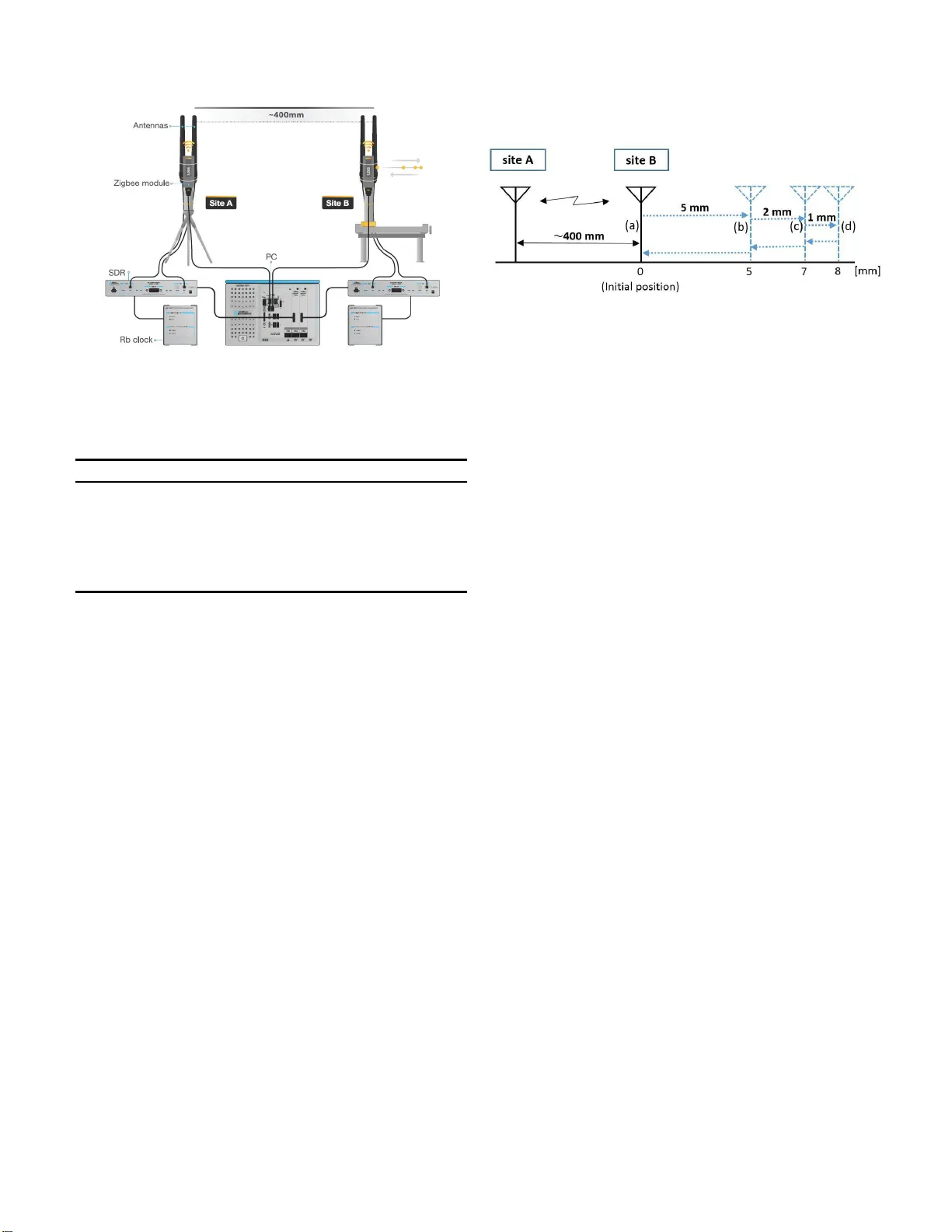
1 Range V ariati on Monitoring with W ireless T wo-W ay Interfer ometry (W i-W i) Bhola R. Panta, K ohta Kido, Satoshi Y asuda, Y uko Hanado, Seiji Kawamura, Hiroshi Hanado , Kenichi T akizawa, Masugi Inoue, and Nobuyasu Shiga Abstract —W e demonstrated a simple tech n ique for monitoring range variation with millimeter -precision between two rem ote sites u si ng off-the-shelf wireless communication modules. The need for the flexible positioning of wireless devices is significantly increasing as more devices are being conn ected and new services are being deve loped that require dev ices to collaborate with one another . W e showed that one can monitor the distance variation by analyzing the propagation delay of the wireless communication signal between devices. W e pre viously reported a techniq ue for synchronizing clocks with picosecond precision by monitoring the time variation of two rub idium clocks located at r emote sites. P recise measur ement of the propagation time variation was necessary fo r precise synchronization of th e clocks, and we used this information to estimate the distance with high precision. In a localized sit uation, our technique makes it easy to implement a mill imeter -p recision measurement system. Furthermore, it i s l ess complex in t erms of system design and can be a low-cost alternativ e to existing systems that require precise position measurement. W e en vision that this d emonstrated protocol will be implemented in wireless communication ch ips and micropro cessing units. Index T erms —Clock synchronization, distance varia tion mon- itoring, milli meter -p recision ranging I . I N T R O D U C T I O N F OR p recise clo ck syn chron ization o r ran g ing, th e Global Navigation Satellite System, p articularly the Global Po- sitioning System (GPS), has become th e d e facto stand ard. Howe ver, the history of ranging using radio w av es goes back to the British Gee and Decca, and Am erican LORAN navigation systems, which used h yperb olic measurem ent tec h niques [1], long before GPS b ecame a household n a me. As the ne ed for short- range distance estimation fo r both outdoo rs and indoo rs grew , rang ing sy stems b ased o n the received signal stren gth (RSS), the time or time difference of a r riv al (T oA /T DoA), the an gle o f ar r iv al (AoA), the phase of arr iv al (PoA) metric wer e extensively researched and m ade av ailab le. So me of th em were p r oposed or surveyed in [2], [3], and [ 4]. Referen ce [5] compare d PoA, and T oA-b a sed ranging behavior for Radio-frequen cy identification (RFID) app lication from the viewpoint of the Cramer-Rao lower bound . By using ray tracin g as well as tak ing measuremen ts in a real en vironm ent, th ey reported that for RFID, Po A-based rangin g Bhola Panta is with E arthquak e Research Institute of the U nive rsity of T okyo, 1-1-1 Y ayoi, Bunkyo-k u, T okyo 113-0032, Japan. The other authors are with National Institute of Information and Communications T echnol ogy (NICT), 4-2-1 Nukui-Kita machi, Kog anei, T okyo 184-8795, Japan. Nobuy asu Shiga is also with PRESTO, Japan Science and T echnology (JST), 4-1-8 Honcho, Kawag uchi, Saitama 332-0012, Japan. Corresponding author email: shiga@nic t.go.jp showed better p erform a n ce than T oA. Ind eed, in [6] a method based on the carr ier pha se of IEEE 8 02.11 wireless LAN was propo sed a n d it was rep orted tha t the meth od was capable of sub-centime ter precision. A recent paper [7] also used phase informa tio n o f the chann e l state inform ation between W i-Fi packets to track the po sition of a virtual- reality h eadset with sub-millimeter precision. Precision ranging and positioning systems based on UWB have also b een proposed , exhib iting sub - centimeter [8] as well as millimeter-lev el [9] precision. More recently , geofencin g systems using RSS-based distance estimation with Bluetooth Low En e rgy have b e come av ailable, such as Apple’ s iBeacon and Google’ s Edd ystone, but they are not g eared tow ards precision ranging. The proposed schemes with hig her precision also tend to be mor e comp lex f or practical implemen tation. For examp le, in the case of [6], th e carrier synch ronization quality and ph ase estimation jitter affect th e results. For the majority of UWB-based transceivers, despite their simp le hardware, most manu factu r ers are una b le to p roduc e in exp e n- si ve transceivers [10]. Laser range fin ders (LRFs) are extensi vely used for prec ise distance measurem ents in con stru ction, manufacturing, land surveying, forestry , and so fo r th. In te r ferome tr ic LRFs provid e better accuracy by measuring the interferen ce be twe e n incident and reflected beams. In [11], we in troduce d th e wireless two-way interf e rometry (W i-Wi) techn ique, which can be considered as an interferom etric ran ge variation measu r ement system using wireless signal. The ubiqu itousness of GPS fo r distan ce measuring a ppli- cations h as alread y been mentioned . However , sev eral factor s must be considered bef ore implementing GPS-based applica- tions. One of the main concern s is the av ailability of the GPS signal. This mean s th at GPS-based application s can o nly be used outdo ors. Even outdoo rs, the req uired n umber of GPS satellites may not be visible in dense, c a nyon-like area s at a giv en time, d egra d ing the perf orman c e o f applications or making th em u nusable. In the experimen t described in this p a per, we measured only the phase of the ca rrier wa ve, so u nlike GPS and LRFs, our experiment does not provide absolute rang e me asurement but the variation of the rang e fro m an initial position. W i- W i ca n b e used indo ors as well as outdoors, including in urban, canyon-like environments. W ith W i- W i, it is possible to implem e nt a pr ecision range- monitor ing system at any time, ind oors or o utdoor s, using off-the-shelf co mpon ents. Considering its lower co mplexity and co st an d ease of u se, a system using Wi -W i h as significant b enefits. 2 I I . S Y S T E M M O D E L A. Calculating Pr o pagation T ime Usin g W i-W i In this section, we explain th e metho d of calc u lating the propag ation time, which is based on th e two-way tim e transfe r (TWTT) [1 2] and two-way carrier ph ase (TWCP) [ 1 3] tech- niques. Fig. 1. System model of W i-Wi. The upper half sho ws the setup of the component s and the lower half shows the time sequence. In Fig. 1, the two W i- W i systems, site A o n th e left and site B on th e r ight, have two identical setups. Transmitters X and Y transmit 2 .4 GHz Zigbee radio signals, and the signal from each transmitter is recei ved at two sites: at the local site and at the remote site. W e exchange the measure d ph ase values between the two sites by includin g phase informatio n in the subsequent packets. For a detailed description of the time seq uence of this proced ure, please refer to section 2.5 of [11]. In th e following deriv ation, we den ote time a s T and the time inter val as t . Let t c be th e time difference between th e time of clock B, T B , and that of clock A, T A , i.e., t c ≡ T B − T A . (1) Let t d be the pro pagation time b etween the two sites. In this study , tran smitter X at site A sends a signal to site B at T X A . After a prop agation time t d , the receiver at site B rec eiv es the signal at T X B . The tim e difference b etween the rec e ption at site B and the tr a n smission at site A, t B , can be expr essed as t B ≡ T X B − T X A = t c + t d . (2) The effect of the prop agation time can be measur ed using the TWTT tech nique. He nce, similar to the above pro c e dure, we send the transmission time of site B to site A. T r ansmitter Y at site B sends the signal to site A at T Y B . After a propag ation time t d , the receiver at site A receives the sig nal at T Y A . The tim e difference between the recep tion at site A an d th e transmission at site B, t A , can b e expre ssed as t A ≡ T Y A − T Y B = − t c + t d . (3) Note that th e transmission times T X A and T Y B are the reception times me a su red at sites A and B with clocks A a n d B, respectively . W e assum e th at the variations in t c and t d during the roun d -trip c o mmun ica tion are n egligible. Adding ( 2) and (3), we ob tain t d = t A + t B 2 . (4) B. Calculating Distance Using Carrier Phase Because Wi-W i uses the TWCP in this experimen t, we rewrite (4) using th e pha se and derive the distance l d between the two sites as l d ≡ c · t d = − φ A + φ B 2 π + K λ 2 , (5) where c is the speed of lig ht, λ is the wav elength of the carrier wa ve, φ A is th e phase a d vance of the transmitted signal after its prop a gation f rom B to A, a n d φ B is the phase advance of the transmitted signal after its pro pagation f rom A to B. W e note th a t the negative sign on the rig ht han d is du e to the definition of φ A and φ B , accord in g to their measur ements at A and B, respectively . Transmitted signal at t = 0 is rec e iv ed and m easured in ref erence to the receiver’ s ph a se at t = t d . As the distanc e l d is incr eased, the measured p h ase of tr a nsmitted signal is shifted n egativ ely . T he me a su red phase can on ly be obtained mo dulo 2 π an d l d can on ly b e obtain ed mo dulo λ /2 . The integer ambigu ity K must be determined separately to obtain th e absolute value of l d . However , by m easuring φ A and φ B repeatedly , the variation from the initial measurem ent can be tracked using the unwrapp ed phase when the variation of φ A and φ B between con secutiv e measureme nts is gu aranteed to b e smaller than π . Th is pr inciple h as been demon strated in [13]. The W i-W i system (Fig. 1) is co nfigured with four clock s. The goa l here is to compa re clock A and clock B by elimi- nating the phase difference between the transmitter ’ s built-in clock (c lock X or clock Y) and the r e ceiv er clock at the same site ( clock A or clo ck B). Below , we d escribe the pr ocedur e . The phase o f clock B with re sp ect to clock A, φ B , is measured u sing transmitter X, and the p hase of clock A with respect to c lo ck B, φ A , is me a su red usin g tr ansmitter Y . They are expr essed as φ B ≡ φ X B − φ X A , (6) φ A ≡ φ Y A − φ Y B , (7) where φ X B denotes th e p h ase o f c lo ck X received at site B and φ X A denotes th e p h ase of clock X received at site A. Similarly , φ Y A denotes the ph ase of clock Y received at site A and φ Y B denotes the phase of clock Y received at site B. A and B denote the locations o f reception . Altho u gh the phases of c locks X and Y have n o cor r elation with the rub idium clock s owing to their ina c curacies, φ B and φ A reflect the phase difference between cloc ks A and B, in cluding th e initial o ffset. I I I . E X P E R I M E N TA L S E T U P Fig. 2 shows a schem atic diag r am o f the set up fo r an ex- periment to demon strate range variation mon itoring using the system described in section II. The experiment was con ducted in an office with sev eral pieces of fu rniture and server cabinets. The f ollowing parag raph describe s the configur a tion setting , including technical specificatio ns. The two sites A and B were separated by about 40 cm. They ha d an iden tical setup and ea c h site co nsisted of a wireless co mmunica tio n mod ule (Zigbee ), a software-de fined 3 Fig. 2. Schematic diagram of the expe rimental setup T ABLE I S P E C I FI C A T I O N S O F I T E M S U S E D I N T H E E X P E R I M E N T Item name Specifica tion/Mo del/Manufacturer Zigbee module Freq.: 2.4 GHz, Power output: 2.5 dBm Model:TWE-Lite-USB , TOCOS (MONOWIRELESS) Rubidium clock SIM940, Stanford Reserach Systems Softwa re radio USRP-2942, National Instruments Personal computer PXIe-1071, National Instruments radio (SDR) with two receivers, and a r u bidium clock . The specifications of eac h eq uipment are sum m arized in T able 1. The Zigb ee m odules were connec te d to a PC throu gh USB cables. The SDRs were refere n ced to 10 MHz, g e nerated by the rub idium clock s, th rough co ax cables. Th e PC and SDRs w e re con nected by PCI Ex press (PCIe) ca bles. Separ ate channels wer e assigned to each Zig bee module at the two lo- cations to av oid cha nnel confu sion. The SDR had two receive channels: channel 1 re c e iv ed the signal from the transmitter a t the local site and channel 2 received the sign al from the r e m ote site. Zigbee co mmunicatio n is based on the IEEE 8 02.15 .4 standard, which employs offset quadr a ture pha se- shift keying (O-QPSK). T ransmitters X an d Y transmitted th e signals alternately at a rate o f app roximate ly 10 times per second. The SDR digitized the baseband in-ph a se (I ) and quadratur e (Q) 16- bit signals at a r a te of 4 m egasam p les/s and the signals were transferred to the PC via the PCIe cable. T he PC d ecoded the signals, symbol by symbol by tak ing the corr e la tio n of the 16 possible chip value seq uences. The phase was measure d for each symbol and the av erage of all the u n wrapped symb o l phases was recorded , which was used to represent the phase of each packet. T o demo nstrate ran g e variation monitorin g , we changed the position of the an tennas of site B by moving the bundled anten nas attached to a stepper moto r , who se step size was 1 µ m. A conceptu al d iagram of the antenna distance variation is shown in Fig. 3. Measure m ents were taken at position s o f 5 mm (b ), 7 mm (c), and 8 mm (d) fro m the initial p osition (a). Then th e measure ment direction was reversed as illustrated in the figu re. Fig. 3. Concept ual diagram of the antenna distance vari ation. (b), (c), and (d) represent distances of 5 mm, an additional 2 mm, and an additi onal 1 mm from the previo us position, respect i vely . The distance was vari ed using a stepper motor . I V . R E S U LT S Fig. 4 shows the measurem ent results. W e measur ed the antenna distanc e variation over a 6 min u te interval. The clo c k difference, plotted in red , varied by ab out 1 ns over that interval, which is r e asonable fo r rub idium clocks. Th e timing and distance of the antenn a movements are indicated in the magnified p lot o f t d , in the lower fig ure. In our pr evious paper [11], we repo rted a d eviation of 2.2 p s in prop agation time measureme nt when the ante n nas were stationary . T his means tha t we can m onitor th e variation o f the d istance between the antennas with 1 mm pre c ision since the wireless signal travels ab o ut 1 mm in 0.3 p s. When we changed the distance by 5, 2 , and 1 mm , the pro pagation time changed by 17, 7, an d 3 ps, respec tively . W e to ok th e average of the sy mbol pha ses over the wh ole packet to repr esent the packet ph ase. Between p ackets, we used unwr apping to calculate t c and t d , as mentione d in the previous section. The u nwrapp ing worked well becau se the distance variation betwe e n adjac e n t measuremen ts was much smaller than 6 cm , which co rrespon d s to a ph ase o f π rad ian. This meth od can measure the d istance variation only whe n the variation between adjace n t mea su rements is guaran teed to be smaller than one half of the wav elength. Note that t c must be continuo us and the refore the stability of the re f erence clock needs to be much better than 0.5 ns (correspo nding to π rad ian) during measuremen t in ter val (0.1 s). V . D I S C U S S I O N A N D C O N C L U S I O N In this pap er , we d emonstrated that the p ropo sed W i-W i system can m onitor the variation of the distance betwee n two anten nas with millimeter precision . Th e c ore id ea of measuring the distance variation between two points is to monitor the ph ase variation of transmitted signals in both directions. As lo ng as one can mon ito r the phase of the transmitted carrier wa ve, W i- W i can achieve rang e variation measuremen t. W e can apply th e metho d describ ed in this pa p er to any commercial communicatio n device. So far , we have carried out tests using 2.4 GHz Zigb e e, Bluetooth Low Energy , and 920 MHz m o dules. 4 Ti m e[s] 0 200 400 t c , t d [ ns ] -0.5 0 0.5 1 1.5 t d t c t [ ps ] ! "# $ "% & ' ( & ) ( * + & * , ! ! "# $ "% & ' ( & ) ( ( - # & - ". "% & ' ( % / 0 ! 400 Ti m e[s] 0 200 400 t d [ ps ] -10 0 10 20 30 1 / / ! 2 / / ! 3 / / ! 4"5 ! 465 ! 4*5 ! 475 ! 3 "! 1 "! Fig. 4. E xperimental result s of W i-Wi . 1) V ariation of clock, t c , and vari ation of propaga tion time, t d , over 6 minute interv al. 2) Magnified plot of t d . T he distanc e betwe en the antennas w as change d using a steppe r m otor as indica ted. Owing to the development of integrated circ uits, many wireless comm unication chips digitize the I and Q sign als of the carrier wav e and process the signal digitally to d ecode the paylo ad. W e en vision that ph a se m easuremen t and W i-W i measuremen t can b e embed d ed in wireless chip s and micr o - processor un its, providin g oppor tunities fo r the extremely low cost and easy implem entation of synchr o nization an d distance measuremen t using any wireless com munication scheme. The Wi-W i system is b ased on interferom etric p hase mea- surements of the carrier wa ve. In this r egard, our techn ique closely re sem bles the pr in ciple of interf erometric LRFs. How- ev er , the LRFs requir e very pre cise beam align ment a nd in practical situations, if the reflector of an LRF is m oved, setting up an d retu ning can be cumber so me. Also, if the reflector is on an inclin e d surface, the measuremen t m ay no t be accurate. On th e other han d, beca u se we used rad io wa ves, a nd since radio wave pro pagation is broad by nature, there is no nee d for precision b eam alig nment, there b y makin g the W i- W i system easy to use. In a localized environment such as a constru c tion site, surveying fo r distance measuremen t to place markers is critical but often carr ied ou t in almost ch aotic environmen t. Therefo re, the ability to set up an d u se a measur ing system on-the- fly is highly d esirable. One of th e promisin g applicatio ns o f p ropag ation measure- ment using W i-Wi is m onitorin g the distance variation between two poin ts. For examp le, one can use this tech nique to monito r small chang es ( ∼ mm) in the length or tilt o f infrastructu re such as towers an d b ridges. Another intere stin g ap p lication could be atmosph eric r e m ote sen sing by mo nitoring the integrated index of refr action (I IR) o f air . Using Wi-W i, the variation o f the prop agation delay , which is mainly due to water vapor , can be estimated with pico second p recision. The prop osed meth od is concep tu ally simple and is attrac- ti ve b ecause of its low complexity and straightfor ward setup to carr y out experime nts. T h e curren t system requ ires r igorou s ev alu ation in multipath environments b efore its p r actical use. W e believe that developing a p prop riate measur es fo r mu ltipath en vironm ent will lead to its wider ad o ption in academic research as well as in ind ustry . V I . F U T U R E D E V E L O P M E N T The proto ty pe version we tested used software radio (USRP) and requ ired AC p ower , and the overall setup is not conduc- ti ve to mob ile use. Miniatu rization of the system is alrea d y underway and we ha ve fabricated a modu le with all th e required compon ents (h igh-pr ecision o scillator , TX/Rx and I/O interfaces), a pro totype of which is curre n tly being tested. A C K N O W L E D G M E N T S This work was su pported b y the JST PREST O program (Grant No. JPMJPR14D5 ) and by NICT . W e tha n k Ryuichi Ichikawa of NI CT for his in sightful co mments. R E F E R E N C E S [1] D. H. C. Scholes, “The use of radio in the navi gation and operation of ci vil aircraft, ” J ournal of the B ritish Institutio n of Radio Engineer s , vol. 12, no. 12, pp. 595-623, Dec. 1952. DOI:10.1049/jb ire.1952.0059 . [2] K. Pahla va n, X. Li, and J. Makela, “Indoor geolocation science and technol ogy , ” IEEE Commun. Mag. , v ol. 40, no. 2, pp. 112- 118, Feb . 2002 [3] R. Miesen, F . Kirsch, P . Groeschel , and M. V oss iek, “Phase based m ulti carrie r ranging for UHF RFID, ” IEE E Int. Conf. on W irele ss Inf . T echnol. and Syst. (ICWITS) , 2012. [4] H. Liu, H. Darabi, P . Banerjee, and J. Liu, “Surve y of wireless indoor positioni ng techni ques and systems, ” IEE E Tr ans. on Systems, Man, and Cybernet ics, P art C (Appli cations and Revie ws) , vol. 37, no. 6, Nov . 2007. [5] Y . Ma, K. Pahla va n and Y . Geng, “Comparison of POA and TO A based ranging behavi or for RFID applicati on, ” IEE E 25th Annual Int. Symposium on P ersonal, Indoor , and Mobile Radio Commun. (PIMRC) , 2014. [6] R. Exel, “Carrier-b ased ranging in IEEE 802.11 wirel ess local area netw orks, ” IEEE W ir eless Commun. and Networkin g Conf. (WCNC) , 2013. [7] M. Kotaru and S. Katti, “Position tracking for virtual reality using com- modity W iFi, ” IEEE Conf. on Computer V ision and P atte rn Recognit ion (CVPR) , July 2017, DOI:10.1109/CVPR.2017.286. [8] A. M. Petrof f, “Ultra W ideband two-w ay time-of-fli ght distance measure- ment pro vides sub-centimete r range measure ment accura cy , ” USNC-URSI Radio Science Meeti ng , P . 212, 2015. [9] C. Zhang, M. J. Kuhn, B. C. Merkl, A. E. Fathy , and M. Mahfouz, “Real -time noncoher ent UWB positioning radar with millimeter range accura cy: th eory and expe riment, ” IEEE T rans. on Micr owave Theory and T echnique s, V ol. 58, no. 1 , J an. 2010, DOI:10.1109/ TMTT . 2009.2035945 . [10] A. Alarifi, A. Al-Salman, M. Alsaleh, A. Alnafessah, S. Al-Hadhra mi, M. A. Al-Ammar , H. S . Al-Khalifa , “Ultra W ideba nd indoor positio ning technol ogies: analysis and rece nt adv ances, ” Sensors 2016 , v ol. 16, no. 707, May 2016. DOI:10.3390/s16050707 . [11] N. Shiga, K. Kido, S. Y asuda, B. Panta, Y . Hanado, S. Kaw amura, H. Hanado, K. T akizawa , and M. Inoue, “Demonstration of wirele ss tw o-way interfe rometry (W i-W i), ” IEICE Comm. Expr ess , vol. 6, no. 2, pp. 77-82, Nov . 2016, DOI:10.1587/ comex.2016 XBL0181 . [12] D. W . Hanson, “Fundamenta ls of two-wa y time transfers by satellit e, ” Pr oceedi ngs of the 43rd Annual Symposium on Fr equency Contr ol , May- June 1989. 10.1109/FREQ.1989.6886 1 . [13] M. Fuji eda, T . Gotoh , F . Naka gaw a, R. T abuc hi, M. Aida, and J . Amagai, “Carrie r-pha se-based tw o-way satelli te ti me and frequenc y transfer , ” IEEE T rans. Ultrason. F err oelec tr . Fr eq. Contr ol , vol. 59, pp. 2625-2630, Dec. 2012, DOI:10.1109/TUFFc.2012.2503.
Original Paper
Loading high-quality paper...
Comments & Academic Discussion
Loading comments...
Leave a Comment