Improved Detection Performance of Passive Radars Exploiting Known Communication Signal Form
In this paper, we address the problem of target detection in passive multiple-input-multiple-output (MIMO) radar networks. A generalized likelihood ratio test is derived, assuming prior knowledge of the signal format used in the non-cooperative trans…
Authors: Anantha K. Karthik, Rick S. Blum
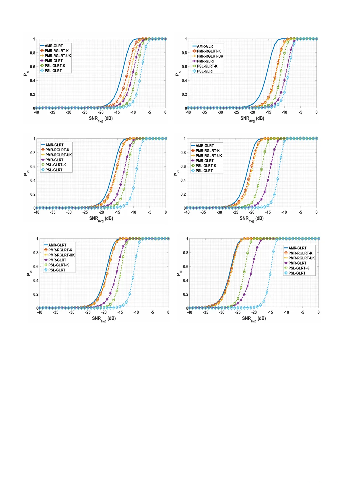
1 Impro v ed Detection Performance of P assi v e Radars Exploiting Kno wn Communication Signal F orm Anantha K. Karthik, Student Member , IEEE and Rick S. Blum, IEEE F ellow Abstract —In this paper , we addr ess the problem of tar get de- tection in passive multiple-input-multiple-output (MIMO) radar networks. A generalized likelihood ratio test is derived, assuming prior knowledge of the signal format used in the non-cooperative transmit stations. W e consider scenarios in which the unknown transmitted signal uses either a linear digital modulation scheme or the Orthogonal Frequency-Di vision Multiplexing (OFDM) modulation scheme. These digital modulation schemes are used in popular standards including Code-Division Multiple Access (CDMA), Digital V ideo Broadcasting-T err estrial (D VB-T) and Long T erm Evaluation (L TE). The perf ormance of the gener - alized likelihood ratio test in the known signal format case is often significantly mor e fav orable when compared to the case that does not exploit this inf ormation. Further , the perf ormance impro ves with increasing number of samples per symbol and, for a sufficiently large number of samples per symbol, the performance closely approximates that of an acti ve radar with a known transmitted signal. Index T erms —Passive Radar , Generalized Likelihood Ratio T est, Code-Division Multiple Access, Digital Video Broadcasting- T errestrial standard, Long T erm Evaluation. I . I N T RO D U C T I O N Passi ve radar dif fers from conv entional activ e radar in that it relies on preexisting signals from non-cooperative trans- mitters instead of transmitting a known signal. Examples of non-cooperativ e transmitters include radio transmitters, TV transmitters, cellular base stations, and other such high power transmitters. Such a system is cost ef ficient, covert, and suitable for emergencies due to the lack of a transmitter . On the other hand, removing the transmitter typically adds significant complexity to the signal processing algorithms needed in the system. Consider a scenario where the passi ve radar system utilizes the signals transmitted from a cellular base station for target detection. Although we do not control the base station, we usually have prior information regarding the position of the transmitter and signal format used in the base station. How- ev er , the transmitted signal still contains unknown information bits, so the signal is not fully kno wn. Prior publications av ail- able in the literature deri ved explicit closed-form expressions for the Generalized Likelihood Ratio T ests (GLR Ts) for target detection in Passiv e MIMO Radar (PMR) networks [1]–[6]. Howe v er , the y did not consider the possibility of exploiting the av ailable signal format information. This material is based upon work partially supported by the U. S. Army Research Laboratory and the U. S. Army Research Office under grant number W911NF-17-1-0331 and by the National Science Foundation under grant no. ECCS-1405579. Anantha K. Karthik and Rick S. Blum are with the Department of Electrical and Computer Engineering, Lehigh University , Bethlehem, P A 18015 USA (e- mail: akk314@lehigh.edu; rblum@lehigh.edu). The authors in [1]–[4] deriv ed the GLR T for target de- tection in PMR networks depending on whether the direct- path reference channel signal is av ailable [1], [2] or not [3], [4]. In [1]–[4], the discrete-time samples of the transmitted signal are assumed to be a deterministic unknown parameter . The transmitted signal along with other unknown parameters are estimated in the GLR T procedure. This work in [1]–[4] appears to be the closest previous work to that discussed in the current paper . Furthermore, the authors in [4] derived the GLR T under conditions where the noise variance is either known or unknown. In [5]–[7], the authors deri ved other GLR Ts for tar get detection in scenarios where the unknown transmitted signal is stochastic. A circular Gaussian random variable with zero mean and unit variance is used to model the transmitted signal. A related paper [7] deri ved the GLR T for PMR networks in which the direct-path and reflected-path signals are not separated. The unknown parameters necessary for the GLR T are estimated using the Expectation-Maximization (EM) algo- rithm. T arget estimation has also been considered for passive radar , see [8]–[10]. In this paper, we study the problem of target detection in PMR networks assuming prior knowledge of the signal format of the transmitted signal. The known signal format scenario is not unrealistic as man y cellular base stations or other transmit stations emit signals according to known standard protocols. In our work, we consider scenarios in which the transmitted signal uses either a linear digital modulation with a known pulse shape or the OFDM modulation scheme. The linear modulation scheme is used in technologies such as CDMA, W ide-band CDMA (WCDMA) and Digital V ideo Broadcasting-Satellite (D VB-S) while technologies such as D VB-T , L TE, and W iMAX incorporate the OFDM modulation scheme. Under the stated assumptions, we deriv e explicit closed- form expressions for a useful relaxed v ersion of the GLR T for target detection in PMR networks depending on whether the noise variance is known or unknown. Numerical results show that the derived GLR Ts perform significantly better than GLR Ts that do not use the signal format information. Further , we observed the performance increases with the number of samples per symbol, and for a suf ficiently large number of samples per symbol, the performance closely approximates that of an acti ve radar where the transmitted signal is entirely known. Finally , the relaxation causes little loss at reasonable signal-to-noise ratios. Notations: W e use bold upper case, bold lower case, and italic lettering to respecti vely denote matrices, column v ectors and scalars. Notations ( . ) T , ( . ) H and ⊗ are the transpose, 2 Hermitian and Kronecker product respectiv ely . I N stands for a N -dimensional identity matrix, 0 N × 1 denotes a column vector of length N with all the elements equal to 0 and || . || is the Frobenius norm. I I . S I G NA L M O D E L A N D P RO B L E M S TA T E M E N T W e adopt the accepted model for PMR networks presented in [1]. W e assume N t transmit stations, N r receiv e stations and orthogonal (or separable) signals sent from each transmit station. The observations receiv ed directly from the transmit- ters are called reference channel signals, while those receiv ed from the possible reflection of the target are called surveillance channel signals. The reference and surv eillance channel signals are separated using beamforming. After isolating the signals, each channel contains a certain amount of noise/clutter in addition to a scaled, delayed, and Doppler-shifted version of the transmitted signal. As in [1], we assume the delay-Doppler compensation accounts for the time delay and frequency shifts on the originally transmitted signal since we are testing for a target with a kno wn position and Doppler . As in [1], we assume the noise/clutter has been whitened. Let s ij s ∈ C N × 1 and s ij r ∈ C N × 1 denote the surveillance and reference channel signals, respecti vely , between the i th transmit station and j th receiv e station. These signals can be represented as s ij s = µ ij s u i + n ij s s ij r = µ ij r u i + n ij r , (1) where µ s ij and µ r ij are the unknown surveillance and reference channel coef ficients, respectively , that include any gain due to beamforming and the noise vectors n r ij and n s ij are circular Gaussian noise, distributed as C N ( 0 N × 1 , σ 2 I N ) with σ 2 denoting the noise variance. Further , u i ∈ C N × 1 contains samples of the unkno wn transmitted signal from the i th transmit station. The PMR detection problem inv olves discriminating be- tween the presence or absence of a target within a hypoth- esized Cartesian position-velocity cell under test [1]. The problem can be formulated as a binary hypothesis test between the target-absent hypothesis ( H 0 ), and the target-present hy- pothesis ( H 1 ) as H 0 : s ij s = n ij s s ij r = µ ij r u i + n ij r H 1 : s ij s = µ ij s u i + n ij s s ij r = µ ij r u i + n ij r , (2) for i = 1 , 2 , · · · , N t and j = 1 , 2 , · · · , N r . In this paper , we only consider scenarios in which the transmitted signal vector u i , can be expressed as u i = G i b i . (3) In (3), G i is a known matrix of appropriate size and b i is a column vector of appropriate size containing unkno wn complex symbols from a digital modulation scheme. In the following subsections, we present communication signals that can be expressed in the form of (3) along with the considered problem statement. A. Linear Digital Modulations The complex baseband structure of a linear digital modulation scheme can be represented as [11] u i ( t + nT sy m ) = M i − 1 X k =0 g i ( t + k T sy m ) b i n − k (4) for 0 ≤ t < T sy m . In (4), i denotes the index of the transmit station, n denotes the symbol number index, b i k denotes the transmitted comple x baseband symbol, T sy m is the symbol period of the digital modulation scheme and g i ( . ) denotes a pulse function of duration M i T sy m used at the i th transmit station. Popular pulse functions include the raised cosine and the root-raised cosine pulse shape [9]. After sampling, (4) can be re written as u i ( pT s + nT sy m ) = M i − 1 X k =0 g i ( pT s + k T sy m ) b i n − k (5) for p = 0 , 1 , · · · , P − 1 , where P denotes the number of samples per symbol. In (5), T s = T sy m /P denotes the sampling interval. Collecting N = LP samples from L consecutiv e symbols inde xed by ( n − L + 1) , ( n − L +2) , · · · , n , the transmitted signal samples can be expressed as u i = G i b i , (6) where u i = [( u i n ) T , ( u i n − 1 ) T , · · · , ( u i n − L +1 ) T ] T with u i k = [ u i ( k T sy m ) , u i ( T s + k T sy m ) , · · · , u i (( P − 1) T s + k T sy m )] T for k = ( n − L + 1) , · · · , n and b i = b i n , b i n − 1 , · · · , b i n − L − M i +2 T . Let G i be an LP × ( L + M i − 1) matrix defined as G i = g i 0 · · · g i ( M i − 1) 0 P × 1 · · · 0 P × 1 0 P × 1 g i 0 · · · g i ( M i − 1) · · · 0 P × 1 . . . . . . . . . . . . 0 P . . . 0 P × 1 0 P × 1 · · · g i 0 · · · g i ( M i − 1) (7) where g i k = [ g i ( k T sy m ) , g i ( T s + k T sy m ) , · · · , g i (( P − 1) T s + k T sy m )] T for k = 0 , 1 , · · · , M i − 1 . B. Orthogonal F r equency-Division Multiplexing Signals The complex baseband structure of an OFDM signal can be represented as [12] u i ( t + nT sy m ) = N s − 1 X l =0 e j 2 π l T u ( t − T g ) b i nl , (8) for 0 ≤ t < T sy m . In (8), i denotes the index of the transmit station, n denotes the OFDM symbol number , N s is the num- ber of subcarriers used in the OFDM signal, b i nl are complex valued modulation symbols, T u is the duration of the useful part of the OFDM symbol (excluding the guard interval), T g is the guard interval duration, and T sy m = ( T u + T g ) is the total OFDM symbol duration. Let T s be the sampling rate equal to T sy m / ( N s P ) , where P is the number of samples per complex symbol. Collecting N = LN s P samples from L consecutiv e OFDM symbols index ed by 0 , 1 , · · · , ( L − 1) , the transmitted signal samples can be expressed as (similar to (6)) u i = ( I L ⊗ H ) b i , (9) 3 where u i = [( u i 0 ) T , ( u i 1 ) T , · · · , ( u i L − 1 ) T ] T with u i k = [ u i ( k T sy m ) , u i ( T s + k T sy m ) , · · · , u i (( N s P − 1) T s + k T sy m )] T for k = 0 , 1 , · · · , L − 1 and b i = [( b i 0 ) T , ( b i 1 ) T , · · · , ( b i L − 1 ) T ] T with b i k = [ b i k 0 , b i k 1 , · · · , b i k ( N s − 1) ] T for k = 0 , 1 , · · · , L − 1 . In (9), H is a N s P × N s matrix whose ml th element is giv en by h ml = e j 2 πl ( mT s − T g ) T u (10) for m = 0 , 1 , · · · , N s P − 1 and l = 0 , 1 , · · · , N s − 1 . C. Pr oblem Statement Under the stated assumptions, the PMR tar get detection prob- lem in (2) can now be written as H 1 : s ij s = µ ij s G i b i + n ij s , s ij r = µ ij r G i b i + n ij r , H 0 : s ij s = n ij s , s ij r = µ ij r G i b i + n ij r , (11) for i = 1 , 2 , · · · , N t and j = 1 , 2 , · · · , N r . In this paper, we deriv e a low complexity approximate GLR T for target detection in PMR networks that uses the av ailable information regarding the signal format of the transmitted signal. W e show significant detection performance improv ement ov er the GLR T which ignores the signal format information. I I I . T A R G E T D E T E C T I O N I N P M R N E T W O R K S Let s ij ( s,r ) denote the vector containing all the observations of all surveillance or reference signals associated with the i th transmit station and let s ( s,r ) denote the concatenation of all s i ( s,r ) , where the notation ( . ) ( s,r ) denotes either ( . ) s or ( . ) r . W e hav e s i ( s,r ) = h ( s i 1 ( s,r ) ) T , · · · , ( s iN r ( s,r ) ) T i T ∈ C N N r × 1 , s ( s,r ) = h ( s 1 ( s,r ) ) T , · · · , ( s N t ( s,r ) ) T i T ∈ C N N r N t × 1 . Let s i = ( s i s ) T , ( s i r ) T T and let s = [ s T s , s T r ] T be the concatenation of all s i . Let µ i ( s,r ) denote the vector of surveillance and reference channel coefficients associated with the i th transmit station and let µ ( s,r ) denote the concatenation of all µ i ( s,r ) across the N t transmit stations defined as µ i ( s,r ) = h µ i 1 ( s,r ) , · · · , µ iN r ( s,r ) i T ∈ C N r × 1 , µ ( s,r ) = h ( µ 1 ( s,r ) ) T , · · · , ( µ N t ( s,r ) ) T i T ∈ C N r N t × 1 . Finally , let u = ( u 1 ) T , · · · , ( u N t ) T T ∈ C N t N × 1 with u i from (3). The receiv ed signals s ij r and s ij s in (1) are parameterized by µ ij r , µ ij s and b i . Since these parameters are unknown to the PMR system, we employ the GLR T for the hypothe- ses testing problem giv en in (11). In GLR Ts, we replace the unknown deterministic quantities with the corresponding maximum likelihood estimates (MLE). Howe ver , obtaining the MLE of the constellation symbols b i k might not be tractable as we would have to search across all possible sequences of b i . Hence, we introduce a relaxation, called the relaxed GLR T , where we allow b i k to be any complex number, i.e., b i k ∈ C as opposed to an actual modulation symbol from the defined finite set. Under this assumption, let b i ∈ C B i × 1 and b = ( b 1 ) T , · · · , ( b N t ) T T ∈ C B× 1 with B = P N t i =1 B i . W e no w present a useful result along with some definitions that will be used extensi vely in the paper . Let A , B ∈ C K × K be Hermitian matrices with A being positiv e semidefinite and B positiv e definite. Definition 1. The gener alized Hermitian eigen value problem is to compute a nonzer o vector w ∈ C K and a r eal number λ such that Aw = λ B w (12) wher e w and the corr esponding λ ar e called the generalized eigen vector and generalized eigen value, respectively [13]. Definition 2. The generalized Rayleigh quotient of the com- plex matrices A and B is a function of w and is defined as R ( w ) = w H Aw w H B w . (13) When A , B are Hermitian matrices with A a positiv e semidefinite matrix and B a positiv e definite matrix, R ( w ) has a maximum value equal to the lar gest generalized eigen v alue of A and B and the value of w that maximizes R ( w ) is the generalized eigen vector of A and B corresponding to the largest generalized eigen value (See Section 4.4.3 of [14] or Theorem 5 . 24 in [14]). In this paper, we denote λ 1 ( A , B ) as the lar gest generalized eigen value of A and B , and v 1 ( A , B ) as the corresponding generalized eigenv ector . A. Relaxed GLRT for PMR Networks When the Signal F ormat Information is Employed and σ 2 is Known W e consider the hypotheses testing problem given in (11). The conditional probability density function (pdf) of s under H 1 is gi ven by p 1 ( s | µ s , µ r , b ) = N t Y i =1 p i 1 ( s i | µ i s , µ i r , b i ) , (14) where p i 1 ( s i | µ i s , µ i r , b i ) ∝ exp − 1 σ 2 N r X j =1 || s ij s − µ ij s G i b i || 2 + || s ij r − µ ij r G i b i || 2 . (15) Similarly , the conditional pdf of s under H 0 is gi ven by p 0 ( s | µ r , b ) = N t Y i =1 p i 0 ( s i | µ i r , b i ) , (16) where p i 0 ( s i | µ i r , b i ) ∝ exp − 1 σ 2 N r X j =1 || s ij r − µ ij r G i b i || 2 . (17) 4 Let l 1 ( µ s , µ r , b | s ) = log p 1 ( s | µ s , µ r , b ) and l 0 ( µ r , b | s ) = log p 0 ( s | µ r , b ) denote the log-likelihood functions under the hypotheses H 1 and H 0 . The relaxed GLR T can now be written as max { µ s , µ r , b }∈ C N r N t × C N r N t × C B l 1 ( µ s , µ r , b | s ) − max { µ r , b }∈ C N r N t × C B l 0 ( µ r , b | s ) H 1 ≷ H 0 κ ksf , (18) where κ ksf denotes a threshold corresponding to a desired value of false alarm probability . It is sho wn in Appendix A that the GLR T -based target detector in (18), termed the P assive MIMO Radar Relaxed GLRT with Known signal format and known noise variance (PMR-RGLRT -K) , is giv en by ξ ksf = 1 σ 2 N t X i =1 h λ 1 ( G i ) H φ i 1 ( φ i 1 ) H G i , ( G i ) H G i − λ 1 ( G i ) H φ i r ( φ i r ) H G i , ( G i ) H G i i H 1 ≷ H 0 κ ksf (19) where φ i 1 = [ φ i s , φ i r ] , and the matrices φ i s and φ i r are defined as φ i ( s,r ) = h s i 1 ( s,r ) , s i 2 ( s,r ) , · · · , s iN r ( s,r ) i ∈ C N × N r . (20) In specific scenarios discussed in [3], [4], the direct path reference channel signals might not be av ailable in the PMR networks. The target detection problem in such scenarios, termed as Passi ve Source Localization (PSL) networks, can be formulated as H 0 : s ij s = n ij s H 1 : s ij s = µ ij s G i b i + n ij s , (21) for i = 1 , 2 , · · · , N t and j = 1 , 2 , · · · , N r . The PSL and PMR hypotheses tests are equiv alent if the PMR system ignores the direct-path reference channel signals s ij r [1]. It is shown in Appendix B that the relaxed GLR T -based target detector that uses the signal structure information, termed the P assive Sour ce Localization Relaxed GLRT with Known signal format and known noise variance (PSL-RGLRT -K) , for the hypotheses testing problem in (21), is given by ξ psk = 1 σ 2 N t X i =1 λ 1 ( G i ) H φ i s ( φ i s ) H G i , ( G i ) H G i H 1 ≷ H 0 κ psk , (22) where κ psk denotes a threshold corresponding to a desired value of false alarm probability . B. GLRT When the Signal F ormat Information is Employed and σ 2 is Unknown When σ 2 is unknown, the conditional pdf of s under H 1 is giv en by p 1 ( s | µ s , µ r , b , σ 2 ) = N t Y i =1 p i 1 ( s i | µ i s , µ i r , b i , σ 2 ) (23) where, p i 1 ( s i | µ i s , µ i r , b i , σ 2 ) = 1 ( π σ 2 ) N r N exp − 1 σ 2 P N r j =1 || s ij s − µ ij s G i b i || 2 + || s ij r − µ ij r G i b i || 2 . (24) The conditional pdf of s under H 0 , p 0 ( s | µ s , µ r , b , σ 2 ) , is similarly defined. Let l 1 ( µ s , µ r , b , σ 2 | s ) = log p 1 ( s | µ s , µ r , b , σ 2 ) and l 0 ( µ r , b , σ 2 | s ) = log p 0 ( s | µ r , b , σ 2 ) denote the log-likelihood functions under the hypotheses H 1 and H 0 . The relaxed GLR T is gi ven by max { µ s , µ r , b ,σ 2 }∈ C N r N t × C N r N t × C B × R + l 1 ( µ s , µ r , b , σ 2 | s ) − max { µ r , b ,σ 2 }∈ C N r N t × C B × R + l 0 ( µ r , b , σ 2 | s ) H 1 ≷ H 0 κ uk , (25) where κ uk denotes a threshold corresponding to a desired value of false alarm probability . It is shown in Appendix C that the GLR T -based target detector in (25), termed the P assive MIMO Radar Relaxed GLRT with unknown noise variance and Known signal format (PMR-RGLRT -UK) , is giv en by ξ uk = P N t i =1 h E i sr − λ 1 ( G i ) H φ i r ( φ i r ) H G i , ( G i ) H G i i P N t i =1 h E i sr − λ 1 ( G i ) H φ i 1 ( φ i 1 ) H G i , ( G i ) H G i i H 1 ≷ H 0 κ uk , (26) where the scalar E i sr = || s i s || 2 + || s i r || 2 . I V . S I M U L A T I O N R E S U LT S In this section, we compare the performance of the proposed GLR T -based target detectors to other GLR T -based detectors av ailable in the literature via numerical simulations. W e briefly describe the considered GLR T -based target detectors: 1) Active (known signal) MIMO Radar GLRT (AMR- GLRT): The binary hypothesis test between the target-absent hypothesis ( H 0 ), and the target-present hypothesis ( H 1 ) in an activ e radar network (where the transmitted signals are kno wn) can be formulated as H 0 : s ij s = n ij s H 1 : s ij s = µ ij s u i + n ij s , (27) for i = 1 , 2 , · · · , N t and j = 1 , 2 , · · · , N r , where the transmitted signal u i is assumed known and the channel coefficients µ ij s are deterministic unkno wns. The GLR T for (27) is given by [15] ξ amr = 1 σ 2 N t X i =1 N r X j =1 | ( u i ) H s ij s | 2 H 1 ≷ H 0 κ amr , (28) where κ amr denotes a threshold corresponding to a desired false alarm probability . 5 2) P assive MIMO Radar GLRT without using the signal format information (PMR-GLRT): The GLR T for target de- tection in PMR networks which does not employ kno wledge of the signal format for the hypotheses testing problem giv en in (2) was deriv ed in [1] and is giv en by ξ pmr = 1 σ 2 N t X i =1 λ ∗ 1 φ i 1 ( φ i 1 ) H − λ ∗ 1 φ i r ( φ i r ) H H 1 ≷ H 0 κ pmr , (29) where κ pmr denotes a threshold corresponding to a desired false alarm probability and λ ∗ 1 ( A ) denotes the largest eigen- value of matrix A . 3) P assive Source Localization GLRT without using the signal format information (PSL-GLRT): The GLR T for target detection in PSL networks which does not employ kno wledge of the signal format for the hypotheses testing problem giv en in (21) was deriv ed in [3] and is giv en by ξ psl = 1 σ 2 N t X i =1 λ ∗ 1 φ i s ( φ i s ) H H 1 ≷ H 0 κ psl , (30) where κ psl denotes a threshold corresponding to a desired false alarm probability . T able I pro vides the test statistics of the various considered GLR T -based detectors. A. Simulation scenario For a fair comparison, we follow the simulation setup of [1]. W e consider a PMR netw ork with N t = 2 transmit stations and N r = 3 receiv e stations. Following [1], we fix || u i || 2 = N . The transmitted signal samples u i are generated according to the chosen signal format in (3) across all transmit stations. The reference and surveillance signal samples are generated on each Monte Carlo trial according to the signal model given in (1). As in [1], the reference channel coefficients, µ i r , are randomly drawn from a C N ( 0 N r , I N r ) distribution on each trial under H 0 and H 1 , and then scaled to achiev e a desired direct-path signal-to-noise ratio (DNR i av g ) according to DNR i av g = || µ i r || 2 N r σ 2 (31) on each trial, where µ i r = [ µ i 1 r , · · · , µ iN r r ] T and | µ ij r | 2 /σ 2 is the DNR of the ij th reference channel. Surveillance channel coefficients are similarly drawn from a C N ( 0 N r , I N r ) distri- bution and scaled to achiev e a desired surveillance signal-to- noise ratio (SNR i av g ) according to SNR i av g = || µ i s || 2 N r σ 2 (32) on each trial, where µ i r = [ µ i 1 r , · · · , µ iN r r ] T and | µ ij s | 2 /σ 2 is the SNR of the ij th surveillance channel. For simplicity , we assume that SNR i av g = SNR av g for all i , i.e., the av- erage surveillance channel target-path SNR across receiv ers is the same for each transmit channel. Similarly , we assume DNR i av g = DNR av g and G i ( . ) = G ( . ) for all i . In our simulations, we consider cases where the transmitted signal is either linearly modulated or follo ws the OFDM modulation scheme. The transmitted signal is generated according to (4) in case of the linear modulations. The complex baseband symbols are chosen from a Binary Phase Shift K eying (BPSK) constellation and g i ( . ) is a raised cosine pulse of roll-off factor 0 . 22 and duration 8 T sy m . When the transmitted signal uses the OFDM modulation, it is generated according to (8). The number of sub-carriers in the OFDM symbol is 16 , the guard-interval duration T g is 0 µs and BPSK symbols are modulated on each sub-carrier of the OFDM symbol. For all the considered target detectors, the detection thresh- old that achiev es a probability of false alarm ( P f ) of 10 − 3 is determined empirically using 10 4 trials under H 0 , and the probability of detection ( P d ) is estimated using 10 4 trials under H 1 . The number of symbols used for target detection in the case of the linearly modulated transmitted signal is 10 (total of 10 P samples), while in the case of the OFDM modulated transmitted signal, we use 1 OFDM symbol (total of 16 P samples). The BPSK symbols used in the generation of the transmitted signal are randomly generated for each Monte- Carlo simulation run. B. Numerical r esults 1) Dependence on SNR av g , DNR av g and P : Figures 1 – 4 show the P d curves as a function of SNR av g for DNR av g = {− 10 , − 5 } dB and for different v alues of samples per symbol, P . As we can see from the numerical results, the proposed target detectors significantly outperform the GLR T -based tar- get detectors that do not use the av ailable signal format information under the considered values of DNR av g for both the PMR and PSL networks. W e also see the GLR Ts for target detection in the PMR networks offer better performance than the GLR T for target detection in PSL networks. This performance gain in the PMR networks is mainly due to the av ailability of the direct-path reference channel signals. The direct-path reference channel signals provide us some knowledge about the transmitted signal depending on the receiv ed strength of these signals [1]. As we see in Figures 1 – 4, the detection performance of relaxed GLR T -based target detectors improves significantly with increasing P when compared to PMR-GLRT and PSL- GLRT 1 . This performance gain is primarily due to the lo wer number of parameters that need to be estimated for the GLR T in the known signal format case. For a sufficiently large value of P , we can also see that the performance of the proposed target detectors is close to that of an active radar, which has complete knowledge of the transmitted signal. Also, at higher values of DNR av g ; the proposed target detectors achiev e near AMR-GLRT lev el performance for smaller values of P . Finally , we observe no significant loss in the detection performance from not kno wing noise variance in the proposed target detectors for all the considered cases. 1 The target detection performance of PMR-GLRT and PSL-GLRT improv e with increasing number of samples. Howe ver , they improve at a much slower rate when compared to the proposed relaxed GLR T -based target detectors. 6 Abbre viation T est Statistic Corresponding References AMR-GLRT 1 σ 2 P N t i =1 P N r j =1 | ( u i ) H s ij s | 2 [15] PMR-GLRT 1 σ 2 P N t i =1 λ ∗ 1 φ i 1 ( φ i 1 ) H − λ ∗ 1 φ i r ( φ i r ) H [1], [2] PSL-GLRT 1 σ 2 P N t i =1 λ ∗ 1 φ i s ( φ i s ) H [3] PMR-RGLRT -K 1 σ 2 P N t i =1 λ 1 ( G i ) H φ i 1 ( φ i 1 ) H G i , ( G i ) H G i − λ 1 ( G i ) H φ i r ( φ i r ) H G i , ( G i ) H G i Proposed in this paper PSL-RGLRT -K 1 σ 2 P N t i =1 λ 1 ( G i ) H φ i s ( φ i s ) H G i , ( G i ) H G i Proposed in this paper PMR-RGLRT -UK P N t i =1 h E i − λ 1 ( ( G i ) H φ i r ( φ i r ) H G i , ( G i ) H G i ) i P N t i =1 h E i − λ 1 ( ( G i ) H φ i 1 ( φ i 1 ) H G i , ( G i ) H G i ) i Proposed in this paper T ABLE I: T est statistics of various GLR T target detectors. 2) P erformance comparison with unr elaxed GLRT (PMR- GLRT -K): In our work, we introduced a relaxation on the complex symbols b i to make the search for the MLE tractable. W e now compare the performance of the relax ed GLR T to the exact unrelaxed GLR T to study the performance loss caused by using the relaxation. The exact GLR T which uses the signal format information is obtained by searching across all possible sequences of b i and finding the sequence that maximizes the likelihood. The P assive MIMO Radar GLRT using the signal format information (abbreviated as PMR-GLRT -K ) is given by max { µ s , µ r , b }∈ C N r N t × C N r N t × A B l 1 ( µ s , µ r , b | s ) − max { µ r , b }∈ C N r N t × A B l 0 ( µ r , b | s ) H 1 ≷ H 0 κ pmrk (33) where κ pmrk denotes a threshold corresponding to a desired false alarm probability and A is the finite set of complex symbols from which the complex symbols b i are taken. For this comparison, the transmitted signal is assumed to be an OFDM signal and is generated according to (8). The number of sub-carriers in the OFDM symbol is 8 , T g is 0 µs and BPSK symbols are modulated on each sub-carrier of the OFDM symbol. W e use 1 OFDM symbol (total of 8 P samples) for target detection. The reference and surv eillance signal sam- ples are generated on each Monte Carlo trial according to the approach described in Section IV -A. The direct-path signal-to- noise ratio, DNR av g , is − 10 dB. The detection threshold that achiev es a ( P f ) of 10 − 3 is determined empirically using 10 4 trials under H 0 , and P d is estimated using 10 4 trials under H 1 . Since b i ∈ A 8 , we search across all 2 8 possible sequences to get the MLE of b i . Figure 5 shows us the performance loss of using the relaxation for different v alues of P . W e can see from the results that the performance loss in the target detection due to the relaxation is relativ ely small and with increasing samples per symbol, there appears to be no performance loss by using the relaxation. V . C O N C L U S I O N This work presented nov el GLR T -based passi ve radar target detectors that can use the av ailable signal format information under conditions where either the noise v ariance is known or unknown. W e restrict ourselves to a particular class of transmitted signals and show that man y important commu- nication signals including CDMA, WCDMA, D VB-S, DVB-T and IEEE 802.16 WiMAX fall under the class of transmitted signals considered in this paper . As demonstrated, adding additional kno wn information about a transmitted signal into the GLR T improves performance in comparison to a GLR T where the information is not utilized, and the signal is con- sidered entirely unknown. Further , giv en an adequate number of samples per symbol, the proposed target detectors may be used to close the performance gap between the passi ve and activ e radar . A P P E N D I X A. Derivation of PMR-RGLRT -K when the signal format in- formation is employed Consider hypothesis H 1 in (11). W e hav e l 1 ( µ s , µ r , b | s ) = N t X i =1 l i 1 ( µ i s , µ i r , b i | s i ) , (34) where (ignoring the additive constants), we hav e l i 1 ( µ i s , µ i r , b i | s i ) = − 1 σ 2 N r X j =1 || s ij s − µ ij s G i b i || 2 + || s ij r − µ ij r G i b i || 2 . (35) The MLE of µ ij ( s,r ) obtained from a deri v ativ e of (35) is giv en by ˆ µ ij ( s,r ) = ( G i b i ) H s ij ( s,r ) ( G i b i ) H G i b i . (36) Substituting (36) into (35), we obtain l i 1 ( µ i s , µ i r , b i | s i ) = − 1 σ 2 N r X j =1 " || s ij s || 2 + || s ij r || 2 − ( G i b i ) H s ij s ( s ij s ) H G i b i ( G i b i ) H G i b i − ( G i b i ) H s ij r ( s ij r ) H G i b i ( G i b i ) H G i b i # . (37) After simplifying, we obtain l i 1 ( ˆ µ i s , ˆ µ i r , b i | s i ) = − 1 σ 2 " E i sr − ( G i b i ) H φ i 1 ( φ i 1 ) H G i b i ( G i b i ) H G i b i # , (38) 7 where φ i 1 = [ φ i s , φ i r ] , and the matrices φ i s and φ i r are defined as φ i ( s,r ) = h s i 1 ( s,r ) , s i 2 ( s,r ) , · · · , s iN r ( s,r ) i and the scalar E i sr = || s i s || 2 + || s i r || 2 . Using the discussion below (13), the complex value of b i that maximizes (38) is giv en by ˆ b i = v 1 ( G i ) H φ i 1 ( φ i 1 ) H G i , ( G i ) H G i . Substitut- ing ˆ b i in (38), we have l i 1 ( ˆ µ i s , ˆ µ i r , ˆ b i | s i ) = − 1 σ 2 E i sr − λ 1 ( G i ) H φ i 1 ( φ i 1 ) H G i , ( G i ) H G i . From (34), we then have l 1 ( ˆ µ s , ˆ µ r , ˆ b | s ) = − 1 σ 2 N t X i =1 E i sr − λ 1 ( G i ) H φ i 1 ( φ i 1 ) H G i , ( G i ) H G i . (39) Follo wing a similar procedure, it can be sho wn under H 0 that l 0 ( ˆ µ r , ˆ b | s ) = − 1 σ 2 N t X i =1 E i sr − λ 1 ( G i ) H φ i r ( φ i r ) H G i , ( G i ) H G i . (40) Using l 1 ( ˆ µ s , ˆ µ r , ˆ b | s ) and l 0 ( ˆ µ r , ˆ b | s ) , the PMR-RGLRT -K for the hypothesis testing problem in (11) is given by ξ ksf = 1 σ 2 N t X i =1 h λ 1 ( G i ) H φ i 1 ( φ i 1 ) H G i , ( G i ) H G i − λ 1 ( G i ) H φ i r ( φ i r ) H G i , ( G i ) H G i i H 1 ≷ H 0 κ ksf . (41) B. Derivation of PSL-RGLRT -K when the signal format infor- mation is employed The conditional probability density function (pdf) of s under H 1 for the hypotheses test of (21) is given by p 1 ( s | µ s , b ) = N t Y i =1 p i 1 ( s i | µ i s , b i ) , (42) where p i 1 ( s i | µ i s , b i ) ∝ exp − 1 σ 2 N r X j =1 || s ij s − µ ij s G i b i || 2 . (43) The conditional pdf of s under H 0 , p 0 ( s ) , is similarly defined. Let l 1 ( µ s , b | s ) = log p 1 ( s | µ s , b ) and l 0 ( s ) = log p 0 ( s ) denote the log-likelihood functions under the hypotheses H 1 and H 0 . The relaxed GLR T can now be written as max { µ s , b }∈ C N r N t × C B l 1 ( µ s , b | s ) − l 0 ( s ) H 1 ≷ H 0 κ psk . (44) Consider hypothesis H 1 . W e hav e l 1 ( µ s , b | s ) = N t X i =1 l i 1 ( µ i s , b i | s i ) , (45) where (ignoring the additive constants), we hav e l i 1 ( µ i s , b i | s i ) = − 1 σ 2 N r X j =1 || s ij s − µ ij s G i b i || 2 . (46) The relaxed MLE of µ ij s and ˆ b i are obtained from a deri v ativ e of (46) and are given by ˆ µ ij s = ( G i b i ) H s ij s ( G i b i ) H G i b i , (47) and ˆ b i = v 1 ( G i ) H φ i s ( φ i s ) H G i , ( G i ) H G i . (48) Substituting the obtained relaxed MLE in (46) and simplifying, we obtain l i 1 ( ˆ µ i s , ˆ b i | s i ) = − 1 σ 2 E i sr − λ 1 ( G i ) H φ i s ( φ i s ) H G i , ( G i ) H G i . From (45), we then have l 1 ( ˆ µ s , ˆ µ r , ˆ b | s ) = − 1 σ 2 N t X i =1 E i sr − λ 1 ( G i ) H φ i s ( φ i s ) H G i , ( G i ) H G i . (49) By a similar procedure, it can shown under H 0 that l 0 ( s ) = − 1 σ 2 N t X i =1 E i sr (50) Using l 1 ( ˆ µ s , ˆ b | s ) and l 0 ( s ) , the PSL-RGLRT -K for the hy- pothesis testing problem in (21) is given by ξ psk = 1 σ 2 N t X i =1 λ 1 ( G i ) H φ i s ( φ i s ) H G i , ( G i ) H G i H 1 ≷ H 0 κ psk . (51) C. Derivation of PMR-RGLRT -UK when the signal format information is employed Consider hypothesis H 1 in (11). W e hav e l 1 ( µ s , µ r , b , σ 2 | s ) = − N t N r N ln( π σ 2 ) − 1 σ 2 N t X i =1 N r X j =1 || s ij s − µ ij s G i b i || 2 + || s ij r − µ ij r G i b i || 2 . (52) From Appendix A, the relaxed MLE of µ ij ( s,r ) and b i are given by ˆ µ ij ( s,r ) = ( G i b i ) H s ij ( s,r ) || G i b i || 2 , (53) 8 and ˆ b i = v 1 ( G i ) H φ i 1 ( φ i 1 ) H G i , ( G i ) H G i . (54) Substituting these values in (52), we obtain l 1 ( ˆ µ s , ˆ µ r , ˆ b , σ 2 | s ) = − N t N r N ln( π σ 2 ) − 1 σ 2 N t X i =1 h E i − λ 1 ( G i ) H φ i 1 ( φ i 1 ) H G i , ( G i ) H G i i . (55) The MLE of σ 2 , denoted by ˆ σ 2 , can be obtained from the deriv ate of (55) and is giv en by ˆ σ 2 = 1 c 1 N t X i =1 h E i − λ 1 ( G i ) H φ i 1 ( φ i 1 ) H G i , ( G i ) H G i i . (56) where c 1 = N t N r N . Substituting the obtained MLE in l 1 ( ˆ µ s , ˆ µ r , ˆ b , σ 2 | s ) and simplifying, we have (ignoring the additiv e constant) l 1 ( ˆ µ s , ˆ µ r , ˆ b , ˆ σ 2 | s ) = − c 1 ln N t X i =1 h E i − λ 1 ( G i ) H φ i 1 ( φ i 1 ) H G i , ( G i ) H G i i ! . By a similar procedure, it can shown under hypotheses H 0 that l 0 ( ˆ µ r , ˆ b , ˆ σ 2 | s ) = − c 1 ln N t X i =1 h E i − λ 1 ( G i ) H φ i r ( φ i r ) H G i , ( G i ) H G i i ! . Using l 1 ( ˆ µ s , ˆ µ r , ˆ b , ˆ σ 2 | s ) and l 0 ( ˆ µ r , ˆ b , ˆ σ 2 | s ) , the PMR- RGLRT -UK for the hypothesis testing problem in (11) is given by ξ uk = P N t i =1 h E i − λ 1 ( G i ) H φ i r ( φ i r ) H G i , ( G i ) H G i i P N t i =1 h E i − λ 1 ( G i ) H φ i 1 ( φ i 1 ) H G i , ( G i ) H G i i H 1 ≷ H 0 κ uk . (57) R E F E R E N C E S [1] D. E. Hack, L. K. Patton, B. Himed, and M. A. Saville, “Detection in Passi ve MIMO Radar Networks, ” IEEE T ransactions on Signal Pr ocessing , vol. 62, no. 11, pp. 2999–3012, June 2014. [2] D. E. Hack, L. K. Patton, and B. Himed, “Detection in Passive MIMO Radar Networks, ” in 2014 IEEE Radar Conference , May 2014, pp. 0780–0785. [3] D. E. Hack, L. K. Patton, B. Himed, and M. A. Saville, “Centralized Passi ve MIMO Radar Detection W ithout Direct-Path Reference Signals, ” IEEE T r ansactions on Signal Pr ocessing , v ol. 62, no. 11, pp. 3013–3023, June 2014. [4] J. Liu, H. Li, and B. Himed, “T wo T ar get Detection Algorithms for Passi ve Multistatic Radar, ” IEEE T ransactions on Signal Pr ocessing , vol. 62, no. 22, pp. 5930–5939, Nov 2014. [5] G. Cui, J. Liu, H. Li, and B. Himed, “T arget detection for Passi ve Radar with Noisy Reference Channel, ” in 2014 IEEE Radar Confer ence , May 2014, pp. 0144–0148. (a) (b) (c) Fig. 1: P d curves as a function of SNR av g when the transmitted signal is linearly modulated with BPSK symbols, L = 10 symbols and DNR av g = − 10 dB for different values of samples per symbol P , (a) P = 4 , (b) P = 16 , (c) P = 64 . [6] Y . W ang, L. L. Scharf, I. Santamara, and H. W ang, “Canonical corre- lations for target detection in a passive radar network, ” in 2016 50th Asilomar Confer ence on Signals, Systems and Computers , Nov 2016, pp. 1159–1163. [7] X. Zhang, H. Li, and B. Himed, “Multistatic Detection for Passive Radar W ith Direct-Path Interference, ” IEEE T ransactions on Aer ospace and Electr onic Systems , vol. 53, no. 2, pp. 915–925, April 2017. [8] Q. He, R. S. Blum, and A. M. Haimovich, “Noncoherent MIMO Radar for Location and V elocity Estimation: More Antennas Means Better Performance, ” IEEE T ransactions on Signal Processing , vol. 58, no. 7, 9 (a) (b) (c) Fig. 2: P d curves as a function of SNR av g when the transmitted signal is linearly modulated with BPSK symbols, L = 10 symbols and DNR av g = − 5 dB for different v alues of samples per symbol P , (a) P = 4 , (b) P = 8 , (c) P = 16 . pp. 3661–3680, July 2010. [9] P . Stinco, M. S. Greco, F . Gini, and M. Rangaswamy , “ Ambiguity func- tion and Cramer-Rao bounds for Univ ersal Mobile T elecommunications System-based Passiv e Coherent Location Systems, ” IET Radar , Sonar Navigation , vol. 6, no. 7, pp. 668–678, August 2012. [10] Q. He and R. S. Blum, “The Significant Gains From Optimally Processed Multiple Signals of Opportunity and Multiple Recei ve Stations in Passi ve Radar, ” IEEE Signal Pr ocessing Letters , v ol. 21, no. 2, pp. 180–184, Feb 2014. [11] J. Proakis and M. Salehi, Digital Communications . McGraw-Hill, 2008. (a) (b) (c) Fig. 3: P d curves as a function of SNR av g when the transmitted signal is an OFDM signal with N s = 16 subcarriers and DNR av g = − 10 dB for different v alues of samples per symbol P , (a) P = 4 , (b) P = 16 , (c) P = 64 . [12] J. E. Palmer and H. A. Harms and S. J. Searle and L. Davis, “D VB- T Passi ve Radar Signal Processing, ” IEEE T ransactions on Signal Pr ocessing , vol. 61, no. 8, pp. 2116–2126, April 2013. [13] X. Feng, X. K ong, Z. Duan, and H. Ma, “ Adaptiv e generalized eigen- pairs extraction algorithms and their conv ergence analysis, ” IEEE T rans- actions on Signal Pr ocessing , vol. 64, no. 11, pp. 2976–2989, June 2016. [14] A. Basilevsk y , Applied Matrix Algebr a in the Statistical Sciences . Dov er Books on Mathematics, Courier Corporation, 2013. [15] Q. He, N. H. Lehmann, R. S. Blum, and A. M. Haimovich, “MIMO Radar Moving T arget Detection in Homogeneous Clutter, ” IEEE T rans- 10 (a) (b) (c) Fig. 4: P d curves as a function of SNR av g when the transmitted signal is an OFDM signal with N s = 16 subcarriers and DNR av g = − 5 dB for dif ferent values of samples per symbol P , (a) P = 4 , (b) P = 8 , (c) P = 16 . actions on Aerospace and Electr onic Systems , vol. 46, no. 3, pp. 1290– 1301, July 2010. (a) (b) (c) Fig. 5: P d curves as a function of SNR av g when the transmitted signal is an OFDM signal with N s = 8 subcarriers and DNR av g = − 10 dB for different v alues of samples per symbol P , (a) P = 4 , (b) P = 8 , (c) P = 16 .
Original Paper
Loading high-quality paper...
Comments & Academic Discussion
Loading comments...
Leave a Comment