Universal Computer aided design for electrical machines
Electrical machines are devices that change either mechanical or electrical energy to the other and also can alternate the voltage levels of an alternating current. The need for electrical machines cannot be overemphasized since they are used in various applications in the world today. Its design is to meet the specifications as stated by the user and this design has to be an economical one. The design, therefore, revolves around designing the machine to meet the stipulated performance required, the cost available and the lasting life of the machine. This work aims to eliminate the tediousness involved in the manual hand calculations of designing the machines by making use of a graphical user interface and using iterations in situations where the data would have been assumed.
💡 Research Summary
**
The paper presents a universal computer‑aided design (CAD) environment that integrates the design of several major types of electrical machines—DC machines, induction motors (single‑phase and three‑phase), synchronous machines (salient‑pole and round‑rotor), transformers (core‑type and shell‑type), and switched reluctance motors (SRM)—into a single graphical user interface (GUI). The authors argue that traditional hand calculations are tedious, error‑prone, and time‑consuming, especially when iterative adjustments are required to meet performance specifications. By providing a menu‑driven GUI with radio‑buttons for machine selection, the tool guides the user through a standardized design workflow: input of machine ratings (voltage, power, current, speed, pole count, etc.), definition of main geometric dimensions, selection of material properties (including B‑H curves), calculation of magnetic and electric loadings, verification of the output coefficient (C₀ = P/(D²·L·N)), performance evaluation (torque, losses, efficiency), and finally generation of CAD drawings for the designed machine.
The design methodology follows the classic analysis‑synthesis approach. For DC, induction, synchronous machines, and transformers, a synthesis method is used: the output coefficient and specific magnetic/electric loadings provide initial estimates of armature diameter (D) and length (L). For the SRM, an analysis method based on the inductance profile versus rotor position is employed, allowing the calculation of aligned and unaligned inductances, torque ripple, and average air‑gap power. The tool includes flowcharts for each machine type, illustrating decision points such as “Is the objective function achieved?” and “Change parameters?” to support iterative refinement.
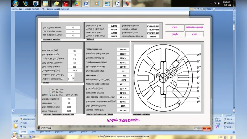
Results are presented as screenshots of the GUI for each machine type, together with corresponding flowcharts. For transformers, the user can select core type, number of phases, and winding configuration; the tool then outputs core dimensions, winding turns, and a CAD model. Induction motor results highlight the influence of slip on torque, showing a characteristic rise in torque with increasing slip up to a peak, after which torque declines. Synchronous motor GUI displays field winding depth, core loss versus flux density, Carter’s coefficient, and open‑circuit characteristics, illustrating magnetic saturation effects at high field currents. The DC machine module provides armature design, commutator/brush layout, and performance checks. The SRM module is the most elaborate: it outputs torque, rotor and stator heights, back‑iron thickness, pole width, turns per phase, and both aligned and unaligned inductance curves. If the average torque does not meet the required value, the user is prompted to modify design parameters such as stator and rotor pole arcs, after which the tool recomputes the performance.
The authors conclude that the universal toolbox successfully automates the preliminary design of a wide range of electrical machines and that the SRM design has been validated using analytical and cyclic integration methods. However, they acknowledge several limitations: the current version does not incorporate cost analysis, material availability, labor constraints, thermal management, or other practical design constraints; therefore, the designs produced are not guaranteed to be optimal for real‑world production. Validation is primarily based on manual calculations rather than experimental prototypes or finite‑element simulations, which reduces confidence for highly nonlinear machines like SRMs. The paper ends with acknowledgments and a list of references covering switched‑reluctance drives, general electrical apparatus design, and CAD of electrical machines.
Comments & Academic Discussion
Loading comments...
Leave a Comment