Mathematical Toolbox and its application in the Development of Laboratory Scale Vertical Axis Wind Turbine
A wind turbine works with the principle of extracting energy from the wind to generate electricity. The power generated is directly proportional to the wind speed available. There are two major types of wind turbine design namely the horizontal and v…
Authors: Aravind CV, Rajparthiban R, Rajprasad R
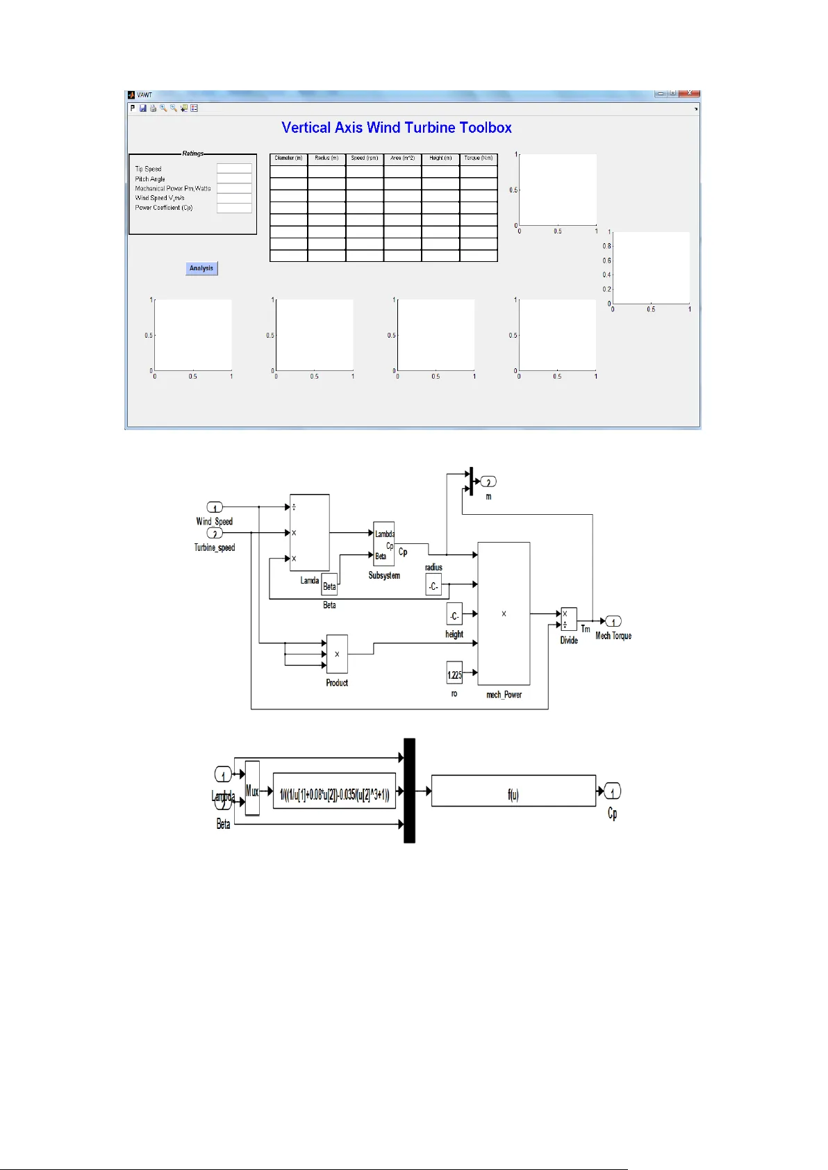
Mathematical Toolbox and its application in the De velopment of Laboratory Scale Vertical Axis Wind Turbine Aravind CV 1 , Rajparth iban R 2 , Rajprasad R 3 , 1 Taylors University, Selangor Malaysia 2 Manipal International Uni versity, Kelanaja ya, Mala ysia 3 University of Nottingham, Mala ysia 1 aravindcv@ieee.org Grace I 4 , Rozita Tey mourz adeh 4 , M.Norhisam 5 4 UCSI University, C heras, Malaysia 5 University Putra Malaysia, S elangor, Malaysia Abstract — Wind turbine w orks with the principle of extracting energy from the wind to generate electricity. The power generated is directly proportio nal t o the wind speed available. There are tw o m ajor types of w ind turbine design namely the horizontal and vertical axis wind turbine depending on the orientation o f th e t urbine rotor and its generator. Th is pape r deals with the design of vertical turbine due to its a dvantage of operating at a low wind speed over that of horizontal turbine. The ana lysis of chan ge in th e pa rameters of a vertical axis w ind turbine is investigated to get the optimized way in w hich the rotor of the turbine is to be designed. This is done through modelling and simulation of the turbine using various parameters in the MATLAB/SIMULINK environment. A graphical user interface is crea ted f or a generic model of vertical axis wind turbine that is used to determine its paramete rs. Keywords-Vertical Axis , SIMULINK, m echanical power, wind turbine I. I NTRODUCTI ON Wind turbine po wer generation are d epends on the w ind speed available and the desi gn of the turbine. T he amount of power derived from the available wind resource using Horizontal Axis Wind Turbine (H AWT) are greatly o n t he radius o f the turbine and the wind speed. The height of the rotor turbine seldom brings effect on its p ower generati on capability . In other words, to have a H AWT turbine, the rotor of the t urbine has to b e placed in a manner in which t he rotor blades are not o bstructed from the wind. This function ma kes th e Vertical Axis Wind Turbine (VAWT) to have a reasonab le edge to that of the H AWT since it does not have to be mounted very h igh. It can be mounted even o n top o f a buildi ng. T he VAWT also has the advanta ge of the height o f the turbine rotor playing a signific ant contribution to t he amount of wind po w er generated. Another major ad vantage o f VAWT over the HAWT is the fact t hat VAWT is suitable at both very low wind spee d and extreme wind speeds whereas HAW T cannot be used in such situations. T he analysis o f VAW T in the paper is for low wind speed of less than 5 m/s . II . D ESIGN OF VAWT To generate power, the tu rbine depends on its physical parameters, wind speed, m echanical speed of the generat or and the tip speed ratio of the turbine. T he average of the wind speed is given b y Eq. (1) (1) where V 1 and V 2 are the inlet and outlet wind speeds in m/s. The derived kinetic energy is given b y Eq. (2) (2) where m is the mass of t he airflow Therefore, the po w er extracte d is given b y Eq. (3) (3) Substituting t he mass i n Eq .( 3) , the power that the rotor can extract from the wind is given in Eq.(4 ) (4) The available p ower from the wind is given b y Eq. (5) (5) And substitutin g the mass, then the availab le po wer is given Eq. (6) (6) Introducing the po wer coefficient as in Eq. (7) (7) Therefore, the mechanical power generated b y the turbine is then seen as i n Eq. (8) (8) where i s air d ensity (kg/m 3) , A is turbine blade area [m 2 ] is the po wer coefficient, V is the wind speed [m/s] [1 ] [4] . The equations required for the design of a vertical wind turbine is similar to that o f horizontal wind turbine. T he difference lies in the area of the different surface o f the type used . The vertical axis wind turbine has its area as Eq. (9) A= 2RH (9) For the horizontal t urbine the ar ea is given as in Eq. (1 0) A = R 2 ( 10 ) where R is the radius of the turbine and H is the height o f the turbine. T his goes to pr ove why t he heig ht o f the rotor is significant for VAWT . T he ratio of the b lade tip speed to the wind stream, the tip spee d ratio is given as i n Eq.(11) (1 1) where V is the wind speed. Based on the tip speed ratio, the power co efficient , the amount of energy that ca n be taken from t he wind is calc ulated as in Eq. (12) (12) The coefficients C 1 to C 6 are: C 1 = 0 .5176, C 2 = 116, C 3 = 0.4, C 4 = 5, C 5 = 2 1 and C 6 = 0.0068 [3] , β is the p itch angle and is angled at which the wind hits the blades. T he equations stated above have bee n implemented in SIMULINK and a grap hical user interface to aid a user in d esigning their own V AWT. Fig. 1 shows the skeleton o f the designed graphical user inter face ( GUI ) whilst the correspo nding modeling blocks is shown in Fig. 2. III . M ODEL A NALY SIS The proposed model is designed w ith para meters as R=0. 2 , H=0.3 .3rad /s, Wind speed =5and N=8 .The model is based partly on the Zephr VAWT and works o n the principle of M AGLEV. Fig. 3 shows the structural characteristics of the VAWT d esigned whilst Fig.4 shows t he fabricated laborator y scaled MAGLEV concept based wind turbine using CAD models developed in principles [6 - 8] . Using the equatio ns stated, =2. 93, C p =0.0455, T m =0.0057 and P m = 0.4177 where T m is the m otor torq ue. This pr oves that the mod el prese nt cannot ge nerate a high-q uality tor que as required . This certainly will affect the p ower co efficient of the wind turbine. The graph of P m versus C p is der ived at various turbine speeds between 1rad/s and 75 rad /s as illustrated in Fig.3. A co mparison of the exper imental result versus t he analytica l result for the curr ent model is shown in the Fi g. 6. I t is found that the a nalytical res ults yields more power as compared t he experimental results because of the d ifference in the improper assumptions made on the analytical. Hence a better analysis on the p arameter has to b e analysed. I n order to improve the design o f the wind turbine the factors influencing are t he power co -efficient Cp , the area of the contact surface and the wind speed. T he wind speed o f the analysis is kept at a constant value and hence the ap proach for im provement of the design is b y var ying C p and by the area of the turbine. To observe the performance of VAWT , the turbine characteristics are simulated for various p arameters such as the different radius, the height, t he t urbine speed, the tip speed ratio while keeping the wind speed at a constant value of 2m/s. Figure 1: Turbine SIMULINK model Figure 2 : Modeling blocks PM Generator Rotor Blade Rotor Plate Base Stand Figure 3: Model design Figure 4 : Fabricated MAGLEV-VAWT 0.005 0.01 0.015 0.02 0.025 0.03 0.035 0.04 0.045 0.05 0 0 0.05 0.1 0.15 0.2 0.25 0.3 0.35 0.4 0.45 0.5 Power co-efficeint (C p ) Mechanical Power 10 20 30 40 50 60 70 80 0 0 0.05 0.1 0.15 0.2 0.25 0.3 0.35 0.4 0.45 0.5 Power co-efficeint (C p ) Mechanical Power Experimental Analytical Figure 5: Graph of P m Vs C p for current model Figure 6: Analytical V s Experimental A. Area o f the turbine From achieving the tip speed r atio, the rad ius of the turb ine rotor is fixed. W ith the given value of t he radi us, and in achieving t he po wer required, the height of t he t urbine can is fixed using Eq. ( 14) (1 4) As see n for a given speci fic req uired mechanical po wer, an increase in the height o f the turbine co mes with a d ecrease in the radius of t he turbine to achieve t he same po w er a nd vice versa. B. Number o f blades In general, it is i mperative that an increase in the number of blades should be better than fewer blades. An i ncrease in t he number o f blades subseq uently reduces the tip speed ratio of the turbine [3]. This therefore r educes the p ower coef ficient leading the turbine to be less efficient than propo sed. T he increase i n t he number of bl ades subseq uently increases the amount o f drag faster than the a mount of power generated . The number of blad es required on the turbine for b est efficiency is between 3 and 4 blad es. C. Turbine Speed The po w er generated fro m t he turbine is further co mputed by using a variab le speed directly dri ven ge nerator like t he PMSG. For the simulatio n therefore, the effect of var ying the turbine spee d is simulated and is see n to increase the power output of the turbine. IV . R ESULTS AND DISCUS SION The anal ysis is performed based on a r equired po wer output o f 35 00W at 250 RPM (26 .18rad/s). The system be havior analysis is obtained by te sting the design with different parameter characteristic. Para meters varied are the height, the radius, the turbine spee d and the tip speed ratio. T he designed toolbox help the designers to derive the closer d imensions for any rating o f capacit y b ut due considerations need to be given to the environment al and mechanical constraints. Howev er, Figure 7 shows the graphical output result from the design e d toolbox and a comprehe nsive analysis is p resented in TABLE 1 . From the GUI result, to get the required speed, based on the calculations as in t he pr evious section the radius of the turbine should be at ab out 0.5 m while the minimum height is kept at about 5.8 m . Wit h t he co nstant value of the radius a nd r otor speed constant, t he power of the wind turbine is seen to increase proportionall y with respect to the increase in the height of the turbine r otor. Keeping t he speed and the height constant, in ord er to achieve t he rated po wer, the radius has to be aro und 0.62 m. Any furth er increase i n the r adius of t he turbine lead s to a subsequent decrease in the power of t he turbine. The above be evidence for the relationship between the radius and height of t he t urbine. To ac hieve t he req uired power, as the radius is incr eased, the height is s een to be decreased until t he rad ius value is close to 0.7 m. At this p oint a subsequent i ncrease in the r adius leads to an increase in t he height. This is b ecause at 0 .7m, the po wer co efficient is at its maximum a nd after this point; it begins to red uce again, leading to t he need for more rad ius and height. Fig ure 7 also shows the relationship bet ween the power required and varying radius and height. F rom the figure graph, the best point for the req uired power i s at the point when the height is about 1200m and the radius is about 0.6 m.The power developed is increased as expec ted with the increa se in t he rotor speed and the relationship bet ween the mechanical power and the tip sp eed r atio at a v arying pitch angle. To achieve the req uired po wer, fro m the graph it s hows that t he tip speed ratio should be app eared less than 8. The relationship between the to rque and the turb ine speed is also shown graphically with the rad ius a nd hei ght o f the rotor is kept at a co nstant val ue. This p roves that the to rque produced b y the wind turbine increase s with increase in mechanical spee d until t he maxi mum torque is achieved. A further increase in the speed then decreases the torque produced. T his is because t he mechanical speed affects t he tip speed ratio and in t urn affects the po wer coefficie nt. After the maximum speed is achieved, a subsequent increase in t he speed increases t he tip speed ratio to more than nine, t hereby reducing the power co efficient. V. C ON CLUSION Th e analytical GUI s ystem is designed and implemented using MATLAB so ftware. Ho wever, I t is found that system pose s different behavior when the mechanical para meters are changed. In order to improve the turbine efficie ncy, t he spe ed, the r adius and t he height of the turbine is to be adjusted accordingly. T his modification can be explained as the following: m m Thi s is to ensure that the tip speed ratio do es not exceed o r is not below the op timum tip spee d ratio. With a variable speed generator the op timum way o f designing the turbine rotor is to design the radius for the maximum speed o f the generator and then design the height for the t orque requi red. REFERENCES [1] maximization of small wind system using permanent magne t Vol.12 Nº2 ( 2009) 307- 319 [2] Paul D., Sandra E., Andreas driven permanent magnet synchronous generator [3] [4] Raju. A .B., Fernandes B.G., Ki simulation of a grid connected variable speed wind energy energy & power Quality Journal , No.1, ( 2003) [5] Siegfried Heier, " Gr id Integration of Wind Energy Conversion Syste ms," John Wiley & Sons Ltd, 1998, I SBN 0-471-97143-X [6] magnetic lev itation assisted vertical axis wind turbine- design and Applications , Melacca, Malaysia CSPA 20 12 [7] Aravind CV, Rozita T, Grace ``Universal Computer Aided Design for Electrical M achine Design'' 8th International Colloquium on Signal Processing and applicat ions, Kualal umpur, Marc h 2012 [8] Grace I, Aravind CV, Rozita T, Samuel B right ``CAD for rotary reluctance motors'' Proceedings of IEEE STUDENT2011 Conference, M alaysia, 20-21 Oct 2011 Figure 7. Results from the GUI developed in MATLAB/SI MULINK 1000 500 1500 2000 2500 3000 3500 4000 Output Power (W) 0 0 500 1000 1500 Height (m) 1000 500 1500 2000 2500 3000 3500 4000 Output Power (W) 0.1 0.2 0.3 0.4 0.5 0.6 0.7 0.8 0.9 1.0 1.1 Radius (m) 0 (a) Output po w er variations to height (b) Output po w er variations to rad ius 0.5 0.55 0.6 0.65 0.7 0.75 0.8 0.85 0.9 500 1000 1500 Height (m) Radius (m) 0 0.1 0.2 0.3 0.4 0.5 0.6 0.7 0.8 0.9 1.0 1000 2000 3000 4000 5000 Output Power Pm (W) Radius (m) (c) Variab le in height to radius used d) Output po w er variations to radius for variou s heights 5 10 15 20 25 30 0 1000 500 1500 2000 2500 3000 3500 4000 Rotational Speed (rad/s) Output Power (W) 0 5 10 15 Tip Speed Ratio 1000 500 1500 2000 2500 3000 3500 4000 Output Power (W) (e) Output po w er variations to speed (f) Output po w er variations to tip speed ratio TABLE 1. Pa rameters for various design values Diameter (m) 0.5 286.4789 6.9107 12.2173 1 0.55 260.4354 6.2825 13.439 1.1 0.6 238.7324 5.7589 14.6608 1.2 0.65 220.3684 5.3159 15.8825 1.3 0.7 204.6278 4.9362 17.1042 1.4 0.75 190.9859 4.6071 18.326 1.5 0.8 179.0493 4.3192 19.5477 1.6 0.85 168.517 4.0651 20.7694 1.7 Radius (m) Speed (rpm) Height (m) Torque (N-m)
Original Paper
Loading high-quality paper...
Comments & Academic Discussion
Loading comments...
Leave a Comment