Practical Implementation of Link Adaptation with Dual Polarized Modulation
The use of dual polarization in mobile satellite systems is very promising for increasing the channel capacity. Polarized Modulation is proposed in this paper for use in practical systems, by providing simple equations for computing its capacity and …
Authors: Anxo Tato, Carlos Mosquera, Pol Henarejos
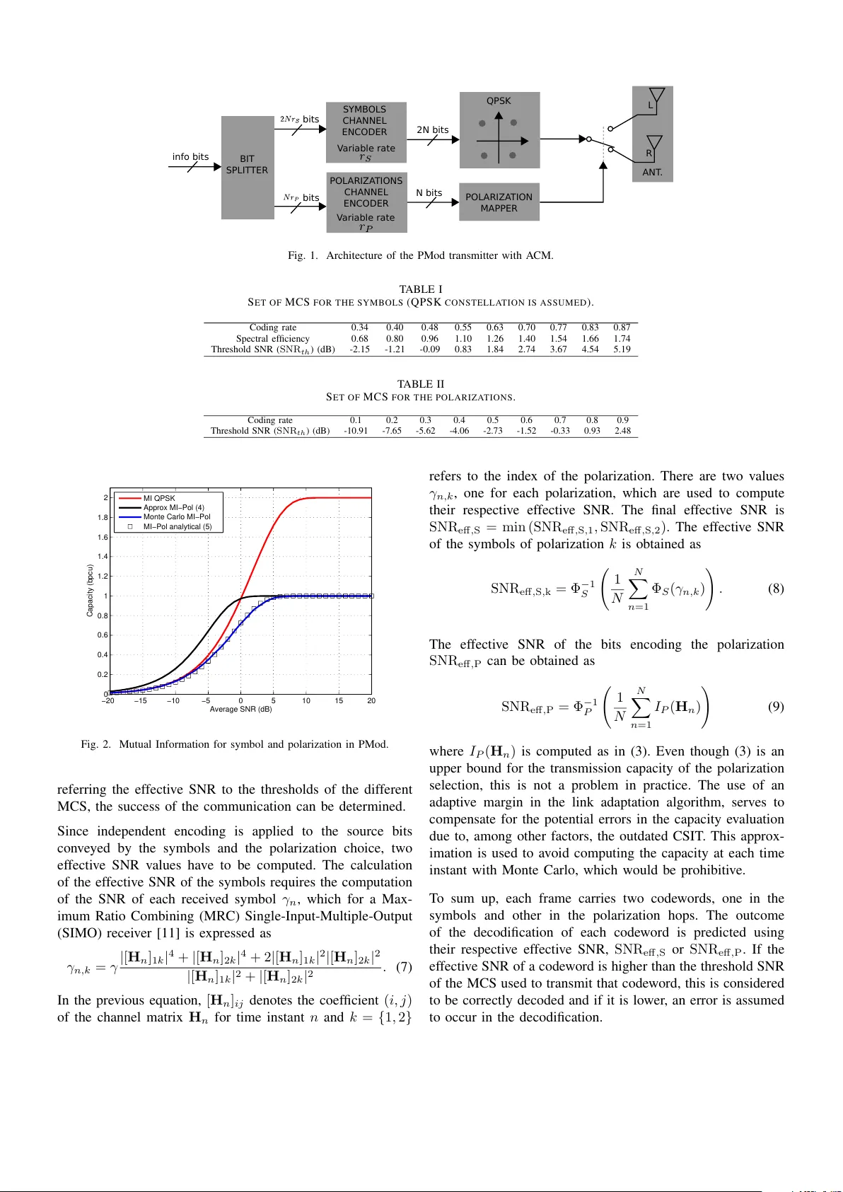
Practical Implementation of Link Adaptation with Dual Polarized Modulation Anxo T ato, Carlos Mosquera atlanTT ic Resear ch Center , Univer sity of V igo V igo, Spain anxotato@gts.uvigo.es, mosquera@gts.uvigo.es Pol Henarejos, Ana P ´ erez-Neira Centr e T ecnol ` ogic de T elecomunicacions de Catalunya (CTTC) Castelldefels, Spain pol.henarejos@cttc.es, ana.perez@cttc.es Abstract —The use of dual polarization in mobile satellite systems is very pr omising for increasing the channel capacity . Polarized Modulation is proposed in this paper f or use in practical systems, by providing simple equations f or computing its capacity and featuring a link adaptation algorithm. This scheme shows remarkable gains in the spectral efficiency when compared with single polarization and other multi-antenna techniques such as V -BLAST . Polarized Modulation is a particular instance of more general Index Modulations, which are being considered for 5G networks. Thus, the proposed link adaptation algorithm could find synergies with current activities for future terrestrial networks. Index T erms —Link Adaptation, Index Modulations, Polarized Modulation, Mobile Satellite, Dual Polarization I . I N T RO D U C T I O N The simultaneous use of tw o polarizations is a means to increase the spectral efficiency that is being explored for mo- bile satellite communications [1]. At low frequencies, like L- and S-band, only one polarization has been traditionally used due to fear to small Cross-Polar-Discriminations (XPD) [2]. Although Right Hand Circular Polarization (RHCP) was the typical option, it is possible to use simultaneously two orthog- onal polarizations, RHCP and Left Hand Circular Polarization (LHCP), to communicate with users. This is analogous to a 2x2 Multiple-Input-Multiple-Output (MIMO) system, simply replacing the spatial by the polarization component. Therefore, the application of MIMO signal processing techniques makes it possible to achieve throughput gains while maintaining the same transmit power , ev en in the presence of interference between polarizations. There are dif ferent MIMO modes which can be employed in the scenario of a mobile satellite system with Dual Polarization (DP) b ut, in practice, only those not requiring Channel State Information at the Transmitter (CSIT) are of interest because of the long propagation delay . T wo candidates are Orthogo- nal Polarization-T ime Block Code (OPTBC), based on 2x2 Alamouti Space-T ime Coding, and V ertical-Bell Laboratory Layered Space-T ime (V -BLAST), a spatial multiplexing tech- nique which transmits two independent streams of symbols, one per each polarization. This work is funded by projects MYRAD A (TEC2016-75103-C2-2-R) and ELISA (TEC2014-59255-C3-1-R). The DP mobile satellite system proposed in [1] and [3] allows the transmitter to switch among different MIMO modes across frames to maximize the spectral efficienc y . Similar adaptation mechanisms take place in other systems such as Long T erm Evolution (L TE) [4]. In addition to OPTBC and V -BLAST , in [3] an additional MIMO mode named Polarized Modulation (PMod) is proposed since it provides many advantages. PMod is a particular type of an Index Modulation which allows a remarkable gain in spectral efficienc y at intermediate SNRs (Signal to Noise Ratios) which cannot be achiev ed by just employing OPTBC and V -BLAST . In PMod two streams of bits are con veyed, one that encodes which symbols of the constellation are transmitted and another stream that indicates which one of the two polarizations is employed to radiate each symbol. Previous works that deal with link adaptation for Index Modulations, like [5] does with Spatial Modulation, only consider adapti ve modulation, i.e., the selection of the modulation order . The novelty of this paper is that we propose the use of two independent variable rate channel encoders, one for each bit stream. In this way the cod- ing rate of each encoder is adapted independently according to the instantaneous channel capacity of each component, the polarizations and the symbols. The aim of this paper is the description of a link adaptation procedure for selecting the Modulation and Coding Scheme (MCS) to be used in a practical implementation of DP system with PMod MIMO mode. Our idea makes use of two inde- pendent Lookup T ables (LUT) for selecting the coding rates of each bit stream. Some adaptiv e mar gins are added to the SNRs at the input of each LUT with the objecti ve to guarantee a predefined Frame Error Rate (FER). Moreover , simulation results are included to show the benefits of exploiting PMod among the MIMO modes of a DP system. Lastly , some results of the capacity for PMod based on recent findings [6] are introduced since they are required in the link adaptation process. The remainder of the paper is structured as follows. Section II provides a brief description of the DP satellite communication system. Section III deals with the capacity computation of the PMod scheme. Then, Section IV describes the Physical Layer Abstraction techniques used in the simulations. After that, Section V introduces the link adaptation algorithm for MCS selection and Section VI provides some simulation results. Lastly , the main conclusions are collected. I I . S Y S T E M M O D E L The forward link of a satellite communication system which serves mobile users in the L-band is considered here, with a transmitter (the gateway) communicating with a receiv er (the Mobile T erminal). Both are equipped with DP antennas and the transmitter always uses the PMod scheme, a particular case of Index Modulations [7] which exploits the polarization flexibility . PMod combines two sources for con veying information: the symbol s , taken from a giv en constellation S , and the polar- ization used to transmit that symbol, l . Hence, in each frame two streams of bits are transmitted: one encoding the radiated symbols and a second stream signalling the polarization of each symbol. Only link adaptation in the forward link is considered here, therefore, the transmitter has to decide the physical layer parameters for each transmitted frame. Fig. 1 shows the architecture of the PMod transmitter with Adapti ve Coding and Modulation (A CM), with two parallel channel encoders with variable and independent coding rates ( r S and r P ) applied to each stream of bits (frames of N symbols are assumed). The purpose of the link adaptation algorithm is to select the MCS, i.e. the coding rate, used in each channel encoder: m S i for the bits which encode the symbols and m P i for the bits which encode the polarizations. W e also assume that there exists a return channel used by the recei ver to feedback the information the link adaptation algorithm needs at the transmitter side: the two effecti ve SNRs and the outcome of the decodification of each codeword, one for each part, symbols and polarizations. The system model of a general DP system for a giv en discrete time instant is y = √ γ Hx + w , (1) where y ∈ C 2 is the received vector , γ is the av erage SNR, H = ( h 1 h 2 ) ∈ C 2 × 2 is the channel matrix, x ∈ C 2 is the transmitted signal and w ∼ C N ( 0 , I 2 ) is the Additive White Gaussian Noise (A WGN). With PMod, since x has always a zero component, (1) can be expressed as y = √ γ h l s + w , with h l the l -column of the channel matrix, where the index l selects the polarization that transmits the complex symbol s . I I I . P M O D C A PAC I T Y In PMod, since the symbol s and the hopping index which selects the polarizations l transmit information, the Mutual Information (MI) between the inputs and the output of the channel can be expressed as I ( y ; s, l ) = I ( y ; s | l ) + I ( y ; l ) = I S + I P , (2) where the MI is expressed as the sum of two components: the capacity of the symbols I S and the polarization bit capacity I P . The capacity of IM is studied in [6] and [8], among others. In [6] a first order approximation of (2) for a general Index Modulation is obtained. From the equation obtained there, which is actually an upper bound, we deriv e the following approximation of the term I P for the particular case of PMod: I P ' log 2 2 1 + e − γ | s | 2 k h 1 − h 2 k 2 . (3) The capacity I P depends on the average SNR γ , the energy of the symbols and the distance between the two columns of the channel matrix H . Equation (3) will be used later to calculate the instantaneous polarization bit capacity in (9). For an A WGN channel, with a normalized diagonal channel matrix H = √ 2 I 2 , and for symbols s with unit energy , (3) is transformed into this equation, I P ' log 2 2 1 + e − 4 γ , (4) which giv es an upper bound of the polarization bit capacity for a diagonal channel. This capacity is represented with a black line in Fig. 2. Howe ver , since the polarization bit capacity I P with that diagonal channel matrix is used alw ays in the last step of the effecti ve SNR calculation, a more accurate equation than (4) will be derived. The real I P , which can be obtained using Monte Carlo to approximate the expectation of Equation (6) of [6], is plotted with a blue line in Fig. 2. Following [9] we ha ve also found that an e xponential function of the form I P ' 1 − e − αγ can perform even better than (4). The value of α estimated using curve fitting with the nonlinear least squares method turns out to be 1 . 30 . Fig. 2 shows ho w this approximation matches tightly the Monte Carlo v alues. Hereafter this capacity will be referred as Φ P ( γ ) : Φ P ( γ ) = 1 − e − 1 . 30 γ . (5) For the sake of completeness, we also include in Fig. 2 the constrained capacity of a Quadrature Phase Shift K eying (QPSK) constellation in an A WGN channel, Φ S ( γ ) , since we will refer to this function in the next section. This capacity can be also approximated by sums of exponential functions as proposed in [9]. Again, we employ the same curve fitting procedure to obtain an analytical expression which matches the QPSK capacity calculated with Monte Carlo. Finally , the expression obtained for the QPSK capacity is Φ S ( γ ) = 2 · 1 − 0 . 8551 · e − 0 . 5718 γ − (1 − 0 . 8551) · e − 1 . 55 γ . (6) I V . P H Y S I C A L L AYE R A B S T R AC T I O N I N P M O D In order to avoid long simulations, resorting to Physical Layer Abstraction techniques [10] is a common practice. A metric named effecti ve SNR condenses in a single value, SNR eff , all the channel variations during a frame spanning N symbols. By SYMB OLS CHANNEL ENCODER bits 2N bits BIT SPLIT TER QPSK POL ARIZA TION MAPPER R L POL ARIZA TIONS CHANNEL ENCODER N bits info bits V ariable r ate V ariable r ate bits ANT . Fig. 1. Architecture of the PMod transmitter with A CM. T ABLE I S E T O F M C S F O R T H E S Y M B O L S ( Q P S K C O N S T E L L A T I O N I S A S S U M E D ) . Coding rate 0.34 0.40 0.48 0.55 0.63 0.70 0.77 0.83 0.87 Spectral ef ficienc y 0.68 0.80 0.96 1.10 1.26 1.40 1.54 1.66 1.74 Threshold SNR ( SNR th ) (dB) -2.15 -1.21 -0.09 0.83 1.84 2.74 3.67 4.54 5.19 T ABLE II S E T O F M C S F O R T H E P O L A R I Z A T I O N S . Coding rate 0.1 0.2 0.3 0.4 0.5 0.6 0.7 0.8 0.9 Threshold SNR ( SNR th ) (dB) -10.91 -7.65 -5.62 -4.06 -2.73 -1.52 -0.33 0.93 2.48 −20 −15 −10 −5 0 5 10 15 20 0 0.2 0.4 0.6 0.8 1 1.2 1.4 1.6 1.8 2 Average SNR (dB) Capacity (bpcu) MI QPSK Approx MI−Pol (4) Monte Carlo MI−Pol MI−Pol analytical (5) Fig. 2. Mutual Information for symbol and polarization in PMod. referring the ef fecti v e SNR to the thresholds of the dif ferent MCS, the success of the communication can be determined. Since independent encoding is applied to the source bits con v e yed by the symbols and the polarization choice, tw o ef fecti v e SNR v alues ha v e to be computed. The calculation of the ef fecti v e SNR of the symbols requires the computation of the SNR of each recei v ed symbol γ n , which for a Max- imum Ratio Combining (MRC) Single-Input-Multiple-Output (SIMO) recei v er [11] is e xpressed as γ n,k = γ | [ H n ] 1 k | 4 + | [ H n ] 2 k | 4 + 2 | [ H n ] 1 k | 2 | [ H n ] 2 k | 2 | [ H n ] 1 k | 2 + | [ H n ] 2 k | 2 . (7) In the pre vious equation, [ H n ] ij denotes the coef ficient ( i, j ) of the channel matrix H n for time instant n and k = { 1 , 2 } refers to the inde x of the polarization. There are tw o v alues γ n,k , one for each po l arization, which are used to compute their respecti v e ef fecti v e SNR. The final ef fecti v e SNR is SNR eff , S = min (SNR eff , S , 1 , SNR eff , S , 2 ) . The ef fecti v e SNR of the symbols of polarization k is obtained as SNR eff , S , k = Φ − 1 S 1 N N X n =1 Φ S ( γ n,k ) ! . (8) The ef fecti v e SNR of the bits encoding the polarization SNR eff , P can be obtained as SNR eff , P = Φ − 1 P 1 N N X n =1 I P ( H n ) ! (9) where I P ( H n ) is computed as in (3). Ev en though (3) is an upper bound for the transmission c apacity of the polarization selection, this is not a problem in practice. The use of an adapti v e mar gin in the link adaptation algorithm, serv es to compensate for the potential errors in the capacity e v aluation due to, among other f actors, the outdated CSIT . This approx- imation is used to a v oid computing the capacity at each time instant with Monte Carlo, which w ould be prohibiti v e. T o sum up, each frame carries tw o code w ords , one in the symbols and other in the polarization hops. The outcome of the decodification of each code w ord is predicted using their respecti v e ef fecti v e SNR, SNR eff , S or SNR eff , P . If the ef fecti v e SNR of a code w ord is higher than the threshold SNR of the MCS used to transmit that code w ord, this is considered to be correctly decoded and if it is lo wer , an error is assumed to occur in the decodification. -5 0 5 10 15 20 25 0 0.5 1 1.5 2 2.5 3 3.5 Fig. 3. Spectral efficienc y of the simulations. -5 0 5 10 15 20 25 0 0.005 0.01 0.015 0.02 0.025 0.03 0.035 0.04 0.045 0.05 Fig. 4. Frame Error Rate of the simulations ( p 0 = 0 . 01 ). V . A L G O R I T H M F O R M C S S E L E C T I O N The selection of both MCS is done by means of two Lookup T ables (LUTs), represented by two step functions, Π S ( · ) and Π P ( · ) , which map SNR interv als to MCS follo wing T ables I-II. On the one hand, the threshold SNRs of T able I are obtained using the function Φ S ( γ ) which giv es the capacity of a QPSK modulation in an A WGN channel. On the other hand, the threshold SNRs for polarization MCS shown in T able II are taken for a diagonal channel matrix and A WGN noise and their values are calculated using the function Φ P ( γ ) . The equations to select the MCS are m S i = Π S (SNR S i − d + c S i ) , m P i = Π P (SNR P i − d + c P i ) , (10) where SNR S i − d and SNR P i − d are the effecti ve SNR for the symbols and the polarizations respectively , calculated by the receiver and sent back to the transmitter through a feedback channel − a Round Trip Time (R TT) of d frames is assumed. c S i and c P i are two adaptive margins updated by the transmitter by using the corresponding received feedback from the other end. The receiv er also informs the transmitter if the codew ords of the symbols and the polarizations were decoded correctly or not by sending two binary v ariables, S i − d and P i − d , which take the value 1 if an error (N AK) has occurred and 0 otherwise (A CK). As in [3], mar gins are updated by a recursi ve equation obtained from the optimization problem min c | E [ ] − p 0 / 2 | 2 , which is based on finding a margin that adjusts the average number of errors in each stream to a predefined v alue p 0 / 2 . Hereafter , only those frames with both codewords (for symbols and polarizations) decoded successfully count as correct for the Frame Error Rate (FER) estimation. Therefore, the margins obtained here are aimed to guarantee a global FER of p 0 . The two equations for updating the margins are c S,i +1 = c S,i − µ ( S,i − d − p 0 / 2) (11) and c P,i +1 = c P,i − µ ( P,i − d − p 0 / 2) , (12) where µ is an adaptation step which in our simulations take the value 0 . 05 . Note that there are two independent margins, c S i and c P i , each one being updated by using their respective acknowledgement ( S,i − d and P,i − d ). When an A CK has been receiv ed the margin is increased by a small quantity , µ · p 0 / 2 , and when an error is reported ( i − d = 1 ) the margin is reduced more drastically by a quantity µ · (1 − p 0 / 2) , which for small values of the objectiv e FER is approximately µ . V I . S I M U L A T I O N R E S U LT S All the simulation results presented here are obtained for a maritime scenario with a vessel moving at a constant speed of 50 km/h. The parameters of the channel generator of the DP mobile satellite system are taken from [12]. The carrier frequency in the simulations is 1 . 6 GHz. Frames of 80 ms and 2560 symbols are used in the physical layer , similarly to the bearer F80T1Q-1B of ETSI TS 102-744 [13]. Each simulation comprises the transmission and reception of M = 40 , 000 frames for a specific average SNR. A verage spectral efficienc y , defined as 1 / M P M i =1 (1 − ( S i + P i ))( r m S i + r m P i ) , and cu- mulativ e FER during the whole transmission is also computed for each simulation. In the previous expression r m S i and r m P i are the rates of the MCS selected for frame i and ( S i + P i ) is the logical OR operation between the two ackno wledgements. Lastly , the R TT is set to 7 frames ( 560 ms) to emulate the feedback delay for geostationary (GEO) satellites. Fig. 3 plots the average spectral ef ficiency for four sets of simulations over a range of average SNRs from -5 to 25 dB. A CM is used in all cases, with the link adaptation algorithm described in this paper for the simulations with PMod and with a similar algorithm for the other modes, as described in [3]. For those simulations with sev eral av ailable MIMO modes, the mode can be switched from frame to frame and its selection is performed according to [3], selecting the mode that maximizes -5 0 5 10 15 20 25 Average SNR (dB) 0.1 0.2 0.3 0.4 0.5 0.6 0.7 0.8 0.9 Coding rates Polarization coding rate Symbols coding rate Fig. 5. Most used coding rate for the symbols channel encoder and polarizations channel encoder . the spectral efficiency gi ven the current value of the effecti ve SNRs of all modes. Firstly , the comparison between mono polarization (SISO curve) and DP in Fig. 3 shows that an increment of up to +50 % in the spectral efficienc y can be achieved with PMod as e xpected when a QPSK constellation is used. For lo w SNRs, this realistic ev aluation of PMod shows that in this scenario there is always a minimum gain of +30 % . These gains can be employed to serve more users or to increase the data rate of the individual users. Note that the same constellation − QPSK − has been used for both SISO and MIMO configurations. In order to match the performance of DP-PMod, the SISO link would require higher order constellations. W ith 8-PSK, the SISO link would perform as DP-PMod with QPSK, only for SNR high enough. More in general, the channel capacity is higher for DP-PMod than for SISO, as easily inferred from Equation (2). Secondly , SISO and PMod are compared with other two DP systems where sev eral MIMO modes are av ailable. In some simulations the modes are only OPTBC and V -BLAST , whereas in other cases these two modes are complemented with PMod. From Fig. 3 it is clear that the inclusion of PMod among the MIMO modes of the DP system is worthwhile. For a range of SNRs from − 2 to 7 dB, PMod provides a spectral efficienc y gain with respect to a configuration where only OPTBC and V -BLAST are used. Thirdly , for systems where high SNRs are achie v able, the V -BLAST mode allows to double the spectral ef ficiency of the Single Polarization sys- tem. Finally , Fig. 4 confirms that the use of the adapti ve margin guarantees a FER around the objectiv e value ( p 0 = 0 . 01 in this case) for a wide range of SNRs and for all the MIMO modes considered here. Lastly , in Fig. 5 we show the most used coding rate for the symbols channel encoder and for the polarizations channel encoder as function of the av erage SNR of the channel γ . As expected, for lower SNRs more protected MCS are selected, i.e., with lower coding rates, and for higher SNRs more efficient MCS are chosen. If we compare this figure with T ables I-II we observe that the ef fective SNR for the polarization SNR eff , P is lower than the average SNR of the channel γ since the channel matrices of the simulated scenario are no longer diagonal as T able II assumes. This leads to the selection of lower rates than one could expect from looking at γ . And, on the other hand, since MRC is used at the receiv er , the po wer received at each polarization contributes to the final SNR of the symbols, leading to the selection of higher coding rates for the symbols that one could expect from looking the γ . All this sho ws the adequacy of using two independent variable rate channel encoders, one for the string of bits which selects the constellation symbols and another for the string of bits which selects the polarizations hops. V I I . C O N C L U S I O N S In this paper we hav e introduced a novel architecture for a Polarized Modulation transmitter based on two independent channel encoders, one for bits encoding the symbols and another for bits encoding the polarizations. Analytical expres- sions to estimate the capacity of each PMOd component are provided, enabling the use of an optimized coding rate in each channel encoder to match their respectiv e channel capacities. A link adaptation algorithm based on a Lookup T able per each component with two independent adaptiv e margins is dev eloped. Simulation results show how PMod outperforms other MIMO modes for an important range of operating SNRs and also how the use of an adaptiv e margin guarantees a fixed Frame Error Rate. Lastly , the dependence of the selected coding rates with the SNR shows the suitability of using two independent channel encoders. R E F E R E N C E S [1] P . Henarejos, A. Perez-Neira, N. Mazzali, and C. Mosquera, “ Advanced signal processing techniques for fixed and mobile satellite communica- tions, ” in 2016 8th Advanced Satellite Multimedia Systems Conference and the 14th Signal Pr ocessing for Space Communications W orkshop (ASMS/SPSC) , Spain, Mallorca, Sept 2016, pp. 1–8. [2] M. Richharia, Mobile Satellite Communications: Principles and T rends , 2nd ed. W iley , 2014. [3] A. T ato, P . Henarejos, C. Mosquera, and A. P ´ erez-Neira, “Link Adap- tation Algorithms for Dual Polarization Mobile Satellite Systems, ” in W ireless and Satellite Systems , P . Pillai, K. Sithamparanathan, G. Gi- ambene, M. ´ A. V ´ azquez, and P . D. Mitchell, Eds. Cham: Springer International Publishing, 2018, pp. 52–61. [4] Q. Li, G. Li, W . Lee, M. i. Lee, D. Mazzarese, B. Clerckx, and Z. Li, “MIMO techniques in W iMAX and L TE: a feature overvie w, ” IEEE Communications Magazine , vol. 48, no. 5, pp. 86–92, May 2010. [5] P . Y ang, M. D. Renzo, Y . Xiao, S. Li, and L. Hanzo, “Design guide- lines for spatial modulation, ” IEEE Communications Surveys T utorials , vol. 17, no. 1, pp. 6–26, Firstquarter 2015. [6] P . Henarejos, A. Perez-Neira, A. T ato, and C. Mosquera, “Channel dependent Mutal Information in Index Modulations, ” in Proceedings. (ICASSP ’18). IEEE International Conference on Acoustics, Speech, and Signal Pr ocessing, 2018. A vailable at http://gpsc.uvigo.es/sites/default/files/publications/ICASSP-CTTC-Pol- vf.pdf, 2018, pp. 1–15. [7] E. Basar, “Index modulation techniques for 5G wireless networks, ” IEEE Communications Magazine , vol. 54, no. 7, pp. 168–175, July 2016. [8] P . Henarejos and A. I. Perez-Neira, “Capacity Analysis of Index Mod- ulations Over Spatial, Polarization, and Frequency Dimensions, ” IEEE T ransactions on Communications , vol. 65, no. 12, pp. 5280–5292, Dec 2017. [9] J. Arnau, A. Rico-Alvarino, and C. Mosquera, “ Adaptive transmission techniques for mobile satellite links, ” in Pr oc. AIAA ICSSC , Ottawa, Canada, Sep. 2012. [10] F . Kaltenberger , I. Latif, and R. Knopp, “On scalability , robustness and accuracy of physical layer abstraction for large-scale system-level ev aluations of L TE networks, ” in 2013 Asilomar Conference on Signals, Systems and Computers , Pacific Grove, California, Nov 2013, pp. 1644– 1648. [11] P . Henarejos, “Polarization and Index Modulations: a Theoretical and Practical Perspecti ve, ” Ph.D. dissertation, Universitat Polit ´ ecnica de Catalunya, Departament de T eoria del Senyal i Comunicacions, 2017. [12] M. Sellathurai, P . Guinand, and J. Lodge, “Space-time coding in mobile satellite communications using dual-polarized channels, ” IEEE T ransactions on V ehicular T echnology , vol. 55, no. 1, pp. 188–199, Jan 2006. [13] “Satellite component of UMTS (S-UMTS); family SL satellite radio interface, ” ETSI TS 102 744 , Oct. 2015.
Original Paper
Loading high-quality paper...
Comments & Academic Discussion
Loading comments...
Leave a Comment