Online Label Recovery for Deep Learning-based Communication through Error Correcting Codes
We demonstrate that error correcting codes (ECCs) can be used to construct a labeled data set for finetuning of "trainable" communication systems without sacrificing resources for the transmission of known symbols. This enables adaptive systems, whic…
Authors: Stefan Schibisch, Sebastian Cammerer, Sebastian D"orner
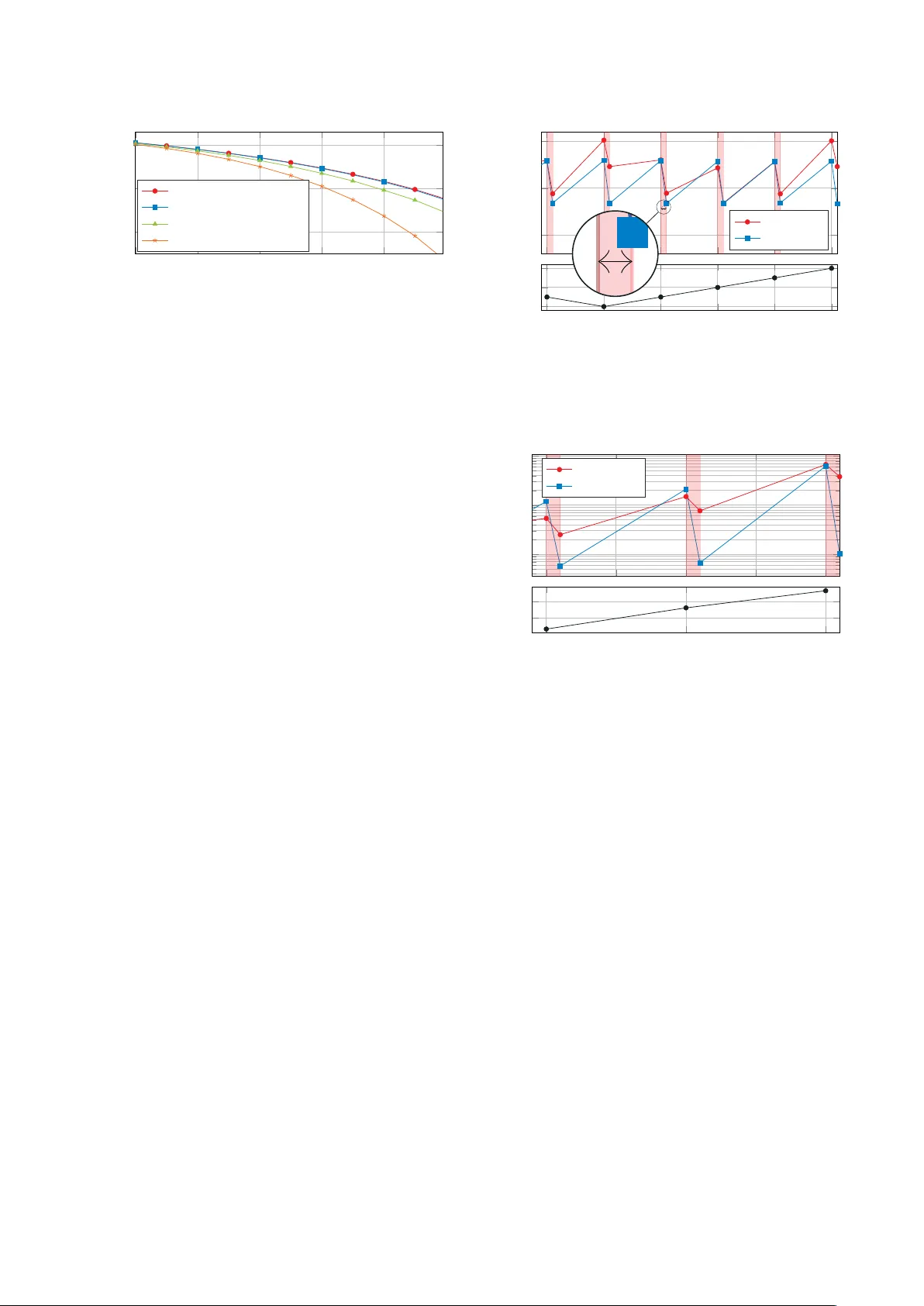
Online Label Reco v ery for Deep Learning-based Communication through Error Correcting Codes Stefan Schibisch ∗ , Sebastian Cammerer ∗ , Sebastian D ¨ orner ∗ , Jakob Hoydis † and Stephan ten Brink ∗ ∗ Institute of T elecommunications, Pfaffenwaldring 47, Uni versity of Stuttgart, 70659 Stuttgart, Germany † Nokia Bell Labs, Route de V illejust, 91620 Nozay , France Abstract —W e demonstrate that error correcting codes (ECCs) can be used to construct a labeled data set for finetuning of “trainable” communication systems without sacrificing resources for the transmission of known symbols. This enables adaptive systems, which can be trained on-the-fly to compensate for slow fluctuations in channel conditions or varying hardware impairments. W e examine the influence of corrupted training data and show that it is crucial to train based on correct labels. The proposed method can be applied to fully end-to-end trained communication systems (autoencoders) as well as systems with only some trainable components. This is exemplified by extending a con ventional OFDM system with a trainable pre-equalizer neural network (NN) that can be optimized at run time. I . I N T R O D U C T I O N Attracted by the conceptual simplicity of deep learning (DL) and the huge success in many fields of application, many papers hav e recently proposed and analyzed ways to benefit from neural networks (NNs) in communications. Therefore, almost any con ventional signal processing block has been replaced individually by NN-blocks such as equalization [1], [2], channel coding [3], [4], detection [5], or multiple-input multiple-output (MIMO)-detection [6] up to DL enhanced iterativ e decoding algorithms [7]. Howev er , with the introduc- tion of end-to-end learning autoencoder systems [8], [9], the system design paradigms change from optimizing indi vidual sub-components with specific task tow ards systems that learn to communicate without the need of any con ventional signal processing block. In classical communication system design, it is assumed that most of the physical effects a transmitted signal suffers from are well kno wn and can be conv entionally corrected one by one due to an approximated channel/system model. Howe ver , minor effects such as temperature changes, non- linearities and tolerance ranges in hardware components, mostly caused by hardware insufficiencies, or other unusual channel parameters (e.g., extreme weather conditions) of- ten cannot be fully considered in those models and, thus, are not optimally compensated. As an alternative approach, NN-enhanced communication promises that the real physical channel with all its known and unknown parameters can be formulated as a hard-to-describe black-box. A neural network- based recei ver (autoencoder systems [8], where transmitter and receiv er are learned together) can be trained such that it This work has been supported by DFG, Germany , under grant BR 3205/6-1. compensates all effects of this black-box without requiring a detailed description or model. This is one promising advantage of deep neural networks in communications. A NN-based system may tolerate a certain mismatch of the channel parameters, but the system itself (without re- training) is static as the weights of the NN do not change once deployed. Howe ver , adaptivity towards fluctuations of the channel condition of NN-based systems can be achiev ed by two dif ferent approaches: 1) Include fluctuations in the training , i.e., the NN is trained to handle these fluctuations and, thus, the system is designed to be adaptive with respect to certain effects. Assuming the effects occur within a certain maximum range (as design parameter of the system). 2) Finetune on-the-fly whenever the channel changes and, thus, only consider the effects when they really occur . Unfortunately , the first approach requires to consider all pos- sible effects during the training (i.e., during the design of the system) and, thus, is often not practical. In this work, we focus on the second approach, i.e., we in vestigate the possibility of finetuning the system on-the-fly . As already mentioned before, the principal benefits of this approach are adaptivity with respect to ef fects not considered during the design, and initial training simplicity as not all possible effects of the future system need to be considered during the design. Howe ver , to ensure that the receiv er neural network can handle channel alterations over time it requires to perform a finetuning step periodically , i.e., the receiver has to update its weights during run time. This can be simply done by the stochastic gradient descent (SGD) algorithm (see [10]), b ut also leads to a fundamental practical problem of NN- based communication systems: How can the r eceiver update its weights without knowing what was originally transmitted , i.e., without having a labeled data set? This may be solved by a periodically transmitted pilot sequence (or explicitly triggered by the receiver if a feedback- channel is av ailable). But this causes overhead and, at least for the case where no feedback-channel is av ailable and the system changes are very sporadic, this approach is infeasible. As SGD based training typically requires a large amount of training samples, pilot based data acquisition causes a high transmission overhead and needs a suitable protocol to trigger the training data acquisition phase between transmitter and receiv er . Both of these problems disappear as soon as the labels y + ˜ y C 2 R FC relu . . . FC linear × α R 2 C f nn ( y , θ ) ˜ y = f eq = y + α · f nn ( y , θ ) Fig. 1: Pre-equalizer residual NN structure. are recov ered from the error correcting code (ECC) assuming a suitable code. Thus, the main contribution of this work is to embed an ECC into NN-enhanced communication systems such that a labeled training set can be generated on-the-fly without any piloting overhead. W e want to clarify that in the context of this work, finetun- ing always relates to the receiver and, thus, not all transmitter impairments can be compensated as the information may already be lost during the transmission (e.g., strong clipping at transmitter side cannot be recovered at the recei ver side). Further , we want to emphasize that the effects we consider in this work are assumed to be slowly changing compared to the run time of the weight update (typically , finetuning requires just a few SGD iterations). I I . D E E P L E A R N I N G - B A S E D C O M M U N I C A T I O N A. Neural Networks In this section, we want to introduce relev ant notations and provide a brief introduction to deep learning fundamentals. The interested reader is referred to [10] for a general intro- duction to the field of DL. Most of the tools and NN structures used throughout this work are very basic and well established within the field of deep learning. In its basic form, a feed- forward NN is a directed computation graph consisting of multiple layers of neurons with connections only to neurons of the subsequent layer . Fully connected (FC) layers, in which ev ery neuron of a layer is connected to all neurons of the previous layer , are called dense layers, because of their densely populated weight matrix, and are the structure of our choice for the later discussed NN. Each neuron within such a dense layer sums up all weighted inputs and optionally applies a non- linear activ ation function, e.g., the rectified linear unit (ReLU) function g ReLU ( x ) = max { 0 , x } before forwarding the output to all connected neurons of the next layer . Let a dense layer i have n i inputs and m i outputs, then it performs the mapping f ( i ) : R n i → R m i defined by the weights and biases as parameters θ i . Consecutiv ely applying this mapping from input v of the first layer to the output w of the last layer, leads to the function w = f ( v ; θ ) = f ( L − 1) f ( L − 2) . . . f (0) ( v ) (1) where θ is the set of parameters and L defines the depth of the net, i.e., the total number of layers. T ABLE I: Parameters used for the pre-EQ Parameter V alue Optimizer SGD with Adam Learning rate L r 0.001 T raining SNR E b / N 0 10 dB and 14 dB Size of Dense Layers 256 neurons Number of Dense Layers: 3 T raining of the NN describes the task of finding suitable weights θ for a given data set and its corresponding labels (desired output of the NN, supervised training) such that a giv en loss function is minimized. This can be efficiently done with the SGD algorithm [10] in combination with weight- backpropagation as implemented in many state-of-the-art soft- ware libraries. W e use the T ensorflow library 1 . While all of the calculations within the neural layers are real-v alued operations, we implemented all operations within the transmission channel as complex operations, since we are dealing with complex signals. Therefore, all complex-valued signals at the NN input are reshaped to real-valued signals with their real and imaginary part consecutiv ely , as well as all real-valued signals at the NN output are transformed back to complex-v alued signals. B. T rainable Communication In principle, recei ver finetuning can be applied as soon as the receiver contains trainable components either as separate entity or embedded in the underlying algorithm. A simple but rather uni versal approach is a pre-equalizer 2 NN (see Fig. 1) directly located at the receiv er input as shown in Fig. 2. The only necessary condition is the a v ailability of the gradient of all operations in the receiver . Therefore, we use a residual [11] structure as shown in Fig. 1 ˜ y = f eq ( y ) = y + α · f nn ( y , θ ) where the scalar α can be optionally an additional trainable parameter . This structure is typically used to overcome the vanishing gradient problem, howe ver , in our context the main motiv ation is that an initialization of α = 0 deacti vates the NN path, i.e., without any training the recei ver behaves exactly as originally designed. T o not restrict us to autoencoder-based communication systems [12] and to demonstrate the conceptual simplicity , we embed a trainable pre-equalizer NN into the receiver of a con ventional orthogonal frequenc y division multiplexing (OFDM) baseline. Thus, we extend a con ventional OFDM system by the proposed equalizer (Fig. 2), where the pre- equalization takes place in the time domain. The OFDM system uses w FFT = 64 subcarriers with cyclic prefix (CP) of length ` CP = 8 , quadrature phase-shift keying (QPSK) modulation per subcarrier and minimum mean squared error (MMSE) equalization per subcarrier , for details we refer to the baseline in [13]. Further , details on the pre-EQ NN are provided in T able. I. 1 www .tensorflow .org 2 Strictly speaking this is not just an equalizer as the NN can learn any non-linear function. u Con v . Enc OFDM- TX Channel f ch ( x , t ) Alteration Pre-EQ OFDM- RX V it. Dec ˆ u Con v . Re-Enc y , ˆ x , ˜ x SGD [ arg min θ ` ( ˆ x , ˜ x ) ] x y ˜ y ˜ x θ ˆ x ˆ u ˜ x = f rx ( y , θ ) TX CH RX ← back-propagation IQ TX ( β I Q ) non-lin ( γ N L ) . . . + N (0 , σ 2 ) IQ RX ( β I Q ) non-lin ( γ N L ) Fig. 2: Communications system including ECC for label recov ery . W e want to emphasize that the proposed training method can be applied to autoencoder-based systems (as used in [9], [13]) straightforwardly , but for the sake of comparison and having a broad field of readers in mind, we provide results only for a conv entional OFDM system with QPSK modulation. 1) Demapping and missing gr adients: Especially the demapping (i.e., the assignment from symbols to a binary decision) can be tricky to implement such that a gradient can be calculated for all layers as the labeling is generally defined by a look-up table (LUT) which does inherently not provide any gradient. Ho wev er , this issue can be solved by changing the classification task into a regression problem. Instead of the cross-entropy loss between the estimated bit sequence and the original sequence, the training can also optimize the mean squared error (MSE) loss between the transmitted symbol (requires OFDM transmitter block at recei ver side) and the estimated symbol at the receiv er before demapping. This makes the training procedure independent of the underlying labeling. For further details on the loss functions we refer to [12], [4], [10]. 2) Initial training of the pre-equalizer NN: In case of a fully NN-based receiver , like the autoencoder system [12], the NN is already optimally trained for all considered fluctuations per design, as described in Section 1. Such a system directly improv es on labeled finetuning training of the receiver part, because the weights only need slight updates. Howe ver , the considered system (Fig. 2) only has a trainable pre-equalizer . Thus, it takes some training time for the pre-equalizer NN to actually improve the recei ver’ s decisions, which we refer to as initial training phase . During this initial training phase, the scalar α is slowly increased by the training process and the pre-equalizer NN gains more influence with more training confidence. T o skip this transient training part for our simulations, we initially trained the pre-equalizer NN for a specific range of shortcoming factors with perfect label knowledge and only the finetuning training updates are based on recovered labels. I I I . O N L I N E L A B E L R E C OV E RY T H R O U G H E C C The proposed system, as depicted in Fig. 2, consists of a con ventional OFDM transmitter and an OFDM recei ver extended by a trainable pre-equalizer (see Sec. II-B). W e use a terminated non-systematic con volutional (NSC) code with encoding memory µ = 2 , polynomials 05 and 07 and, thus, of rate r = 0 . 5 . 3 The encoder maps k information bits u into a codeword x of length N . After passing through the channel f ch ( x , t ) , the (noisy) sequence y can be observed at the receiv er (consisting of the pre-equalizer and the con ventional OFDM receiver), which then provides an estimate ˜ x on the transmitted codeword. The decoder uses the V iterbi algorithm with traceback length 5( µ + 1) and outputs the corrected information bit sequence ˆ u . A final re-encoding step provides the (estimated) codew ord ˆ x . During data transmission, the receiver collects a training set consisting of observations of the received sequence y , the estimated code word ˜ x and corrected codew ord ˆ x as label for the training. 4 For a giv en loss function ` ( x , y ) the task of the SGD is then defined as θ new = arg min θ ` ( ˆ x , ˜ x ) = arg min θ ` ( ˆ x , f rx ( y , θ old )) . The finetuning can be either triggered periodically or when- ev er a certain bit error rate (BER) threshold is e xceeded, this threshold has to be chosen such that the ECC can recov er (almost) all errors in the codew ord. For simplicity , we use a periodic weight update in the following part of this work. T o allow a meaningful examination of the influence of time- varying hardware impairments, we model such effects by a single parameter per effect. The v ariations are thus simulated by a simple random walk model for this sole parameter . The effects we consider are: 1) IQ-imbalance: we use a simple model only depending on a single parameter β IQ ∈ R as y = β IQ · R ( x ) + (1 − β IQ ) · j · I ( x ) (2) 2) Non-linearity and clipping: we model this effect by a single parameter γ NL ∈ R describing AM-AM distortion by a third-order non-linear function with normalized input as giv en in [14] g ( x ) = x − γ NL | x | 2 x (3) 3 Besides con volutional codes, any other channel coding scheme such as low-density parity-check (LDPC) codes and Polar codes could be applied straightforwardly . W e opted for conv olutional codes as it provides a flexible codew ord length. T o avoid high simulation complexity in combination with the Python/T ensorflow setup, we limit µ = 2 , howev er , further gains are expected with increasing µ . 4 Remark: ˜ x and ˆ x do not need to be stored necessarily , as they can be calculated during the forward-propagation of the SGD anyway . 4 6 8 10 12 10 − 5 10 − 3 10 − 1 SNR [dB] pre-ECC SER Baseline: no Finetuning Scenario 1: corrupted data Scenario 2: correct data Scenario 3: corrected data Fig. 3: Impact of corrupted training data during finetuning of a trainable OFDM communications system suf fering from TX IQ-imbalance. All setups use the same amount of 20,000 OFDM symbols as training data, collected at SNR of 5 dB, which equals a pre-ECC SER of 9.6%. with x ∈ C and | x | in [0 , 1] , i.e., we clip x such that | x | ≤ 1 and keep the phase of x unchanged. Furthermore, the channel adds additi ve white Gaussian noise (A WGN). A. T raining with corrupted labels W e first analyze the impact of corrupt labels during training for IQ-imbalance. Thus, we analyze three different scenarios: 1) Training set contains corrupted data, i.e., transmission errors are not detected/corrected 2) Training set contains only the correctly receiv ed sym- bols, i.e., transmission errors are detected but not cor- rected (e.g., due to a cyclic redundanc y check (CRC)) 3) All symbols in the training set are correct, i.e., trans- mission errors are corrected (ECC) T o av oid side ef fects, all training data sets have the same size of 20 batches with 1,000 OFDM symbols per batch. Fig. 3 depicts the same finetuning step (from β IQ = 0 . 45 to β IQ = 0 . 65 ) for the listed scenarios and shows that finetuning based on corrupted labels does not significantly improv e the pr e-ECC performance of the trainable OFDM system. It also shows that finetuning based only on correctly received symbols helps improving the performance slightly , but as somehow expected and shown in Fig. 3, the performance increases significantly if corrected (via ECC) symbols are used as labels during the finetuning process. In other words fr om err ors one learns . I V . A DA P T I V I T Y In the following, we show that the proposed finetuning can be used to compensate impairments on-the-fly and without the need of explicit labels. The underlying channel parameters β IQ and γ NL are provided in Fig. 4 and Fig. 5, respectively . The horizontal red lines indicate that a finetuning step was triggered and the weights are updated. As the considered effects are typically slowly changing, it seems to be reason- able to assume that an unlimited amount of training data is av ailable. During each time step ∆ t , N ∆ t OFDM symbols are transmitted and used for the finetuning procedure. The system performs 7 finetuning SGD iterations per time step using all N ∆ t OFDM symbols. 10 − 3 . 5 10 − 3 10 − 2 . 5 θ update pre-ECC SER TX IQ-Imb RX IQ-Imb n n + ∆ t n + 2∆ t n + 3∆ t n + 4∆ t 0 . 4 0 . 5 0 . 6 time β I Q 10 − 3 . 5 10 − 3 10 − 2 . 5 θ update pre-ECC SER TX IQ-Imb RX IQ-Imb n n + ∆ t n + 2∆ t n + 3∆ t n + 4∆ t 0 . 4 0 . 5 0 . 6 time β I Q Fig. 4: SER performance at SNR of 10 dB for varying IQ- imbalance β IQ . The horizontal red areas indicate receiver finetuning solely based on labels recovered at the receiver . N ∆ t = 5 , 000 OFDM symbols are transmitted and used for training per time step. 10 − 5 10 − 4 10 − 3 pre-ECC SER TX Non-Lin RX Non-Lin n n + ∆ t n + 2∆ t − 14 − 12 time EVM [dB] Fig. 5: SER performance at SNR of 14 dB for varying non-linearity γ . The horizontal red areas indicate recei ver finetuning solely based on labels recovered at the receiver . N ∆ t = 20 , 000 OFDM symbols are transmitted and used for training per time step. A. IQ-Imbalance In this experiment, we study the impact of IQ-imbalance as giv en in (2) for transmitter and receiv er side, respectiv ely . The system is originally trained for β IQ = 0 . 5 , howe ver , we assume that β IQ now changes during time as sho wn in Fig. 4. In Fig. 4, it can be seen that both effects, transmitter and receiv er IQ-imbalance, can be compensated with the residual network by only using the received data. As expected, the transmitter is slightly harder to compensate, but generally tolerates IQ- imbalance. K eep in mind that only the receiv er weights are updated during the finetuning. B. Non-linearity In the next experiment, we examine the impact of a non- linearity and clipping as giv en in (3) (no IQ-imbalance as- sumed), again at transmitter and receiver side. As the transmit- ter does not change during finetuning, we can provide the error vector magnitude (EVM) caused by the non-linearity (see [13]) as shown in Fig. 5. The non-linearity turns out to be much harder to compensate when compared to IQ-imbalance, which 10 − 3 10 − 2 10 − 1 pre-ECC SER no finetuning N θ = 4 N ∆ t N θ = 2 N ∆ t N θ = N ∆ t θ update n n + ∆ t n + 2∆ t n + 3∆ t 0 . 45 0 . 5 0 . 55 0 . 6 time β I Q Fig. 6: SER performance at SNR of 10 dB for posterior finetuning for varying IQ-imbalance. could be explained by the fact that the non-linearity and the clipping effect destroy the transmitted information irreversibly rather than just cause a distortion. Howe ver , finetuning can still improv e the recei ver performance significantly as shown in Fig. 5. Again, we observe that the transmitter non-linearity is more difficult to compensate than the receiv er side non- linearity . C. P osterior Finetuning W e now analyze the impact of outdated weights during the decoding. This could be practically motiv ated whenev er the coherence time of the channel is belo w the training time required for finetuning. Therefore, we assume that during a time step ∆ t an amount of N ∆ t OFDM symbols is transmitted with constant channel conditions. A practical motiv ation of this scenario may be the downlink in deep space communica- tion where the signal is fully recorded at the receiver and the ground station may have (almost) infinite resources to recov er the signal without further latency constraints. Due to outdated weights, or in other words when the mismatch between trained and actual channel conditions is too lar ge, the recei ver operates at high BER which cannot be compensated by the ECC (see red curve Fig. 6). Thus, the finetuning gains are degraded due to spoiled labels (see Fig. 3). T o ov ercome this problem, we propose posterior finetuning 5 in such a way that intermediate weight updates are only based on a subset of N θ ≤ N ∆ t OFDM symbols. The detailed algorithm is giv en in Algorithm 1, where N θ denotes the number of OFDM symbols used for the SGD update ( window- size ). As can be seen in Fig. 6 for the effect of IQ-imbalance, a proper choice of N θ (in relation to N ∆ t ) can improv e the decoding performance significantly . V . C O N C L U S I O N S A N D O U T L O O K W e have examined the possibilities of mitigating the in- fluence of corrupted labels for finetuning of the trainable components by using an ECC and, thus, to recov er a labeled training set on the receiver side without knowing the trans- mitted sequence, i.e., without the need for pilots. This is due to the fact that we deal with man-made signals and, thus, can influence the structure of the transmitted data by adding 5 In case the required time for finetuning t f t > ∆ t , posterior decoding may be based on a recorded sequence and, thus, the name posterior . Algorithm 1: Posterior Finetuning Input : Number of OFDM-symb . per SGD update N θ Recorded sequence of m · N θ OFDM-symbols Y = [ y 0 , . . . , y m · N θ − 1 ] Pre-trained pre-equalizer weights θ Output: Estimated information bit sequence ˆ U = [ ˆ u 0 , . . . , ˆ u m · N θ − 1 ] / * Sliding window decoding * / for τ ← 0 to m − 1 do / * Receive with given weights θ * / [ ˆ u τ · N θ , . . . , ˆ u ( τ +1) · N θ − 1 ] ← decode ( θ ; [ y τ · N θ , . . . , y ( τ +1) · N θ − 1 ]) / * Re-encode * / [ ˆ x τ · N θ , . . . , ˆ x ( τ +1) · N θ − 1 ] ← re-encode ([ ˆ u τ · N θ , . . . , ˆ u ( τ +1) · N θ − 1 ]) / * Update weights θ * / θ ← sgd ([ y τ · N θ , ..., y ( τ +1) · N θ − 1 ]; [ ˆ x τ · N θ , ..., ˆ x ( τ +1) · N θ − 1 ]) end redundancy . W e have shown that the proposed method can compensate unforeseen impairments without being explicitly considered in the original design of the system. This has been ex emplified by inducing IQ-imbalance and non-linearity in both transmitter and receiver . As expected, effects occurring at the transmitter side are much harder to compensate than receiv er side ef fects. R E F E R E N C E S [1] A. Caciularu and D. Burshtein, “Blind channel equalization using variational autoencoders, ” arXiv pr eprint arXiv:1803.01526 , 2018. [2] D. Neumann, T . W iese, and W . Utschick, “Learning the MMSE channel estimator , ” IEEE T ransactions on Signal Pr ocessing , 2018. [3] E. Nachmani, E. Marciano, D. Burshtein, and Y . Be’ery , “RNN decoding of linear block codes, ” arXiv preprint , 2017. [4] T . Gruber, S. Cammerer , J. Hoydis, and S. ten Brink, “On deep learning- based channel decoding, ” in Pr oc. of CISS , 2017. [5] N. Farsad and A. Goldsmith, “Detection algorithms for communication systems using deep learning, ” arXiv preprint , 2017. [6] N. Samuel, T . Diskin, and A. W iesel, “Deep MIMO detection, ” SP A WC , pp. 690–694, 2017. [7] E. Nachmani, Y . Be’ery , and D. Burshtein, “Learning to decode lin- ear codes using deep learning, ” 54th Annu. Allerton Conf. Commun., Contr ol, Comput. (Allerton) , pp. 341–346, 2016. [8] T . J. O’Shea, K. Karra, and T . C. Clancy , “Learning to communicate: Channel auto-encoders, domain specific regularizers, and attention, ” IEEE Int. Symp. Signal Pr ocess. Inform. T ech. (ISSPIT) , pp. 223–228, 2016. [9] S. D ¨ orner , S. Cammerer, J. Hoydis, and S. ten Brink, “Deep learning- based communication over the air , ” IEEE Journal of Selected T opics in Signal Processing , 2018. [10] I. Goodfellow , Y . Bengio, and A. Courville, Deep Learning . MIT Press, 2016. [11] K. He, X. Zhang, S. Ren, and J. Sun, “Deep residual learning for image recognition, ” in Pr oceedings of the IEEE conference on computer vision and pattern recognition , 2016, pp. 770–778. [12] T . J. O’Shea and J. Hoydis, “ An introduction to machine learning com- munications systems, ” IEEE T ransactions on Cognitive Communications and Networking , vol. 3, no. 4, pp. 563–575, Dec 2017. [13] A. Felix, S. Cammerer, S. D ¨ orner, J. Hoydis, and S. ten Brink, “OFDM- Autoencoder for End-to-End Learning of Communications Systems, ” ArXiv e-prints . [14] T . Schenk, RF imperfections in high-rate wireless systems: impact and digital compensation . Springer Science & Business Media, 2008.
Original Paper
Loading high-quality paper...
Comments & Academic Discussion
Loading comments...
Leave a Comment