Versatile Mobile Communications Simulation: The Vienna 5G Link Level Simulator
Research and development of mobile communications systems require a detailed analysis and evaluation of novel technologies to further enhance spectral efficiency, connectivity and reliability. Due to the exponentially increasing demand of mobile broa…
Authors: Stefan Pratschner, Bashar Tahir, Ljiljana Marijanovic
Pratschner et al. RESEARCH V ersatile Mobile Communications Simulation: The Vienna 5G Link Level Simulato r Stefan Pratschner 1 , 2 * , Basha r T ahir 1 , 2 , Ljiljana Ma rijanovic 1 , 2 , Ma riam Mussbah 2 , Kiril Kirev 2 , Ronald Nissel 1 , 2 , Stefan Schw a rz 1 , 2 and Ma rkus Rupp 2 Abstract Resea rch and development of mobile communications systems require a detailed analysis and evaluation of novel technologies to further enhance sp ectral efficiency , connectivity and reliability . Due to the exp onentially increasing demand of mobile broadband data rates and challenging requirements for latency and reliability , mobile communications sp ecifications b ecome increasingly complex to supp o rt ever more sophisticated techniques. Fo r this reason, analytic analysis as well as measurement based investigations of link level metho ds so on encounter feasibility limitations. Therefore, computer aided numeric simulation is an imp o rtant to ol for investigation of wireless communications standards and is indisp ensable for analysis and developing future technologies. In this contribution, we intro duce the Vienna 5G Link Level Simulator, a Ma tlab -based link level simulation to ol to facilitate research and development of 5G and b ey ond mobile communications. Our simulato r enables standard compliant setups according to 4G Long T erm Evolution, 5G new radio and even b ey ond, making it a very flexible simulation to ol. Offered under an academic use license to fellow researchers it considerably enhances reproducibility in wireless communications research. W e give a brief overview of our simulation platform and intro duce unique features of our link le vel simulato r in more detail to outline its versatile functionality . Keyw o rds: mobile communications; 5G; new radio; link level simulation 1 Intro duction Link level measurements, analysis and simulation are fundamen tal tools in the dev elopment of no vel wireless comm unication systems, each offering its own unique b enefits. Measurements provide the basis for c hannel mo deling and are th us a prerequisite of analysis and sim ulations. F urthermore, measurement-based exp er- imen ts presen t the ultimate p erformance b enc hmark of any transceiver architecture and are therefore in- disp ensable in the system developmen t cycle. How- ev er, p erforming measuremen ts is very costly , time consuming and hard to adapt to sp ecific communica- tion scenarios; hence, their application is commonly k ept at a necessary minimum. Compared to that, link lev el simulations facilitate rapid protot yping and com- parison of comp eting tec hnologies, enabling to gauge the p oten tial of such tec hnologies early on in the re- searc h and developmen t pro cess. A big adv antage of analytic inv estigations is their p oten tial to reveal piv- otal relationships amongst k ey parameters of a sys- * Correspondence: spratsch@nt.tu wien.ac.at 1 Christian Doppler Laborato ry for Dependable Wireless Connectivit y for the Society in Motion Full list of author information is available at the end of the article tem; yet, analytic tractability often requires applica- tion of restrictiv e assumptions and simplifications, lim- iting the v alue of analytic results under realistic con- ditions. T o inv estigate highly complex systems, such as wireless transceivers, and to efficiently ev aluate the p erformance of no vel technologies, link level simula- tions are thus often the preferred method of choice, en- abling the incorp oration of realistic and practical con- strain ts/restrictions, which in many cases significantly alter the picture drawn by purely analytic inv estiga- tions. Nevertheless, only by complemen ting measure- men ts, analysis and simulations it is p ossible to reap the b enefits of all three approaches. In this pap er, we present the newest member of our suite of Vienna Cellular Communications Simulators (V CCS): the Vienna 5G link level (LL) Sim ulator. Our mobile comm unications researc h group at the Institute of T elecommunications at TU Wien has a long and successful history of developing and sharing standard- complian t cellular communications simulators under an academic use license, with the goal of enhancing repro ducibilit y in wireless communications academic researc h [ 1 , 2 ]. The implementation of our work-horse Pratschner et al. Page 2 of 15 of the past nine years, that is, the Vienna L TE Sim- ulators [ 3 ], started back in 2009, leading to three re- liable standard complian t L TE simulators: a downlink system lev el simulator [ 4 , 5 ] and tw o link level sim- ulators, one for uplink [ 6 ] and one for do wnlink [ 7 ]. T o da y the Vienna L TE Simulators count more than 50 000 do wnloads in total. Ev en though the path of 3rd Generation P artnership Pro ject (3GPP) tow ards 5G is largely based on Long T erm Evolution (L TE), w e so on recognized that evolving our L TE sim ulators tow ards 5G is not straightforw ard due to a lack of flexibility of the simulation platform in terms of implementation and functionalit y . Mobile communications within 5G is exp ected to supp ort muc h more heterogeneous and v ersatile use cases, suc h as enhanced mobile broad- band (eMBB), massiv e mac hine-type communication (mMTC) or ultra-reliable and low-latency communi- cation (uRLLC), as compared to 4G. F urthermore, a m ultitude of nov el concepts and contender technolo- gies within 5G, e.g., full-dimension/massiv e MIMO b eamforming [ 8 , 9 , 10 ], mixed numerology m ulticar- rier transmission [ 11 , 12 ], non-orthogonal multiple ac- cess [ 13 , 14 ], and transmission in the millimeter wa v e (mmW av e) band [ 15 , 16 ], requires careful identifica- tion, abstraction and mo deling of k ey parameters that impact the p erformance of the system. W e therefore decided to rather inv est the required implementation effort into new simulators to extend our VCCS sim- ulator suite and to ev olve to the next generation of mobile communications with dedicated 5G link and system level simulators. The Vienna 5G LL Sim ulator fo cuses on the physi- cal lay er (PHY) of the communication system. Cor- resp ondingly , the scop e is on p oin t-to-p oin t simula- tions of the transmitter-receiver c hain (channel co ding, m ultiple-input m ultiple-output (MIMO) pro cessing, m ulticarrier mo dulation, c hannel estimation, equaliza- tion,...) supp orting a broad range of simulation param- eters. Nevertheless, multi-point communications with a small num ber of transmitters and receiv ers are p os- sible (limited only by computational complexity) to sim ulate, e.g., m ulti-p oin t preco ding techniques [ 17 ], rate splitting approaches [ 18 ], in terference alignment concepts [ 19 ]. The transmission of signals ov er wireless c hannels thereby is implemented up to the individual signal samples and thus provides a v ery high level of detail and accuracy . The Vienna 5G LL Simulator mo dels the shared data c hannels of b oth, uplink and downlink trans- missions, that is, the physical downlink shared chan- nel (PDSCH) and the physical uplink shared channel (PUSCH). The simulator is implemented in Ma tlab utilizing ob ject orien ted programming metho ds and its source co de is av ailable for download under an aca- demic use license [ 2 ]; hence, w e attempt to contin ue our successful approach of facilitating repro ducible re- searc h with this unifying simulation platform. The sim ulator allows for (and includes) parameter settings that lead to standard complian t systems, including L TE as w ell as 5G. Y et, the versatile functionalit y of the sim ulator pro vides the opp ortunit y to go far b e- y ond standard compliant simulations, enabling, e.g., the ev aluation of a cornucopia of different combina- tions of PHY settings as well as the co-existence in- v estigation of candidate 5 G technologies. The Vienna 5G LL Sim ulator acts in close orchestration with its sibling the Vienna 5G system level (SL) Simulator: the LL simulator is employ ed to determine the PHY abstraction mo dels utilized on SL to facilitate com- putationally efficient simulation of large-scale mobile net w orks. 2 Scientific Contribution Computer aided numerical sim ulations are a well es- tablished to ol for analysis and ev aluation of wireless comm unications systems. Hence, a num b er of commer- cial and academic link level sim ulators is offered online. Amongst these tools, our new Vienna 5G LL Simulator supp orts a v ariet y of unique features as w ell as a highly flexible implementation structure that allows for easy in tegration of additional comp onen ts. In this section, w e provide an ov erview of existing similar simulation platforms and compare them to our new sim ulator. W e thereb y restrict to academic to ols that are, as our sim- ulator, av ailable for free, and lea ve as id e commercial sim ulators. F urther, we p oin t out the distinct features offered b y the Vienna 5G LL Simulator and thereby state our scientific contribution. 2.1 Related Wo rk - Existing Simulation T o ols With each new wireless communications standard, the need for simulation emerges. This is necessary for the ev aluation, comparison and further research as well as the developmen t of communication schemes, sp ecified within a certain standard. The existence of v arious sim ulation to ols for the PHY of L TE, such as [ 20 , 21 ] or the Vienna L TE-A LL Sim ulator [ 7 , 6 , 3 ], dev elop ed by our research group, supp orts this claim. These to ols, ho w ever, are mainly based on 3GPP Release 8 to Re- lease 10 and do not offer features and functionalit y sp ecified and exp ected for 5G. There exist some com- mercial pro ducts, that is, link level simulators, that claim to supp ort simulation of 5G scenarios. Ho w ever, as we aim to supp ort academic research also b ey ond the currently standardized features, we compare our Vienna 5G LL Simulator to other freely av ailable aca- demic sim ulators only . An ov erview of existing LL sim- ulation to ols is provided in T ab. 1 . The GTEC 5G LL Simulator is an op en source link level simulator developed at the Universit y of A Pratschner et al. Page 3 of 15 T able 1 Overview of existing LL simulators. simulator property language/platform multi-link waveforms channel co des flexible numerology GTEC 5G LL Simulator Ma tlab no OFDM,FBMC - no ns-3 C++, Python yes - (PHY model) - (PHY model) no OpenAirInterface C yes OFDM turbo no Vienna 5G LL Simulator Ma tlab yes CP-OFDM,f-OFDM, FBMC,UFMC,WOLA LDPC, turbo, polar, convolutional yes Coru ˜ na [ 22 ]. It is based on Ma tlab and offers highly flexible implementation based on mo dules. By imple- men tation of new mo dules, it is even p ossible to simu- late different wireless communications standards, such as WiMAX or 5G. The current 5G mo dule offers tw o PHY transmission w av eforms, namely orthogonal fre- quency division multiplexing (OFDM) and filter-bank m ulticarrier (FBMC). F orward error correction chan- nel coding is not supp orted. F urther, this sim ulator fo- cuses on single-link p erformance and does neither sup- p ort multi-user nor m ulti-transmitter (multi base sta- tion (BS)) scenarios. Simulating inter-user interference (IUI) of non-orthogonal users, e.g., non-orthogonal m ultiple access (NOMA) or mixed numerology use- cases, is not p ossible with this to ol. A well known to ol for sim ulation of communications net w orks is the ns-3 simulator [ 23 ], which is the suc- cessor of the ns-2 simulator . Although this to ol has to b e understo od as a set of op en source mo dules forming a generic net w ork sim ulator, there exists an L TE mod- ule [ 24 ] that allows to simulate 4G netw orks. F urther, there exists a mo dule [ 25 , 26 ] that cov ers mmW av e propagation asp ects of 5G. Still, the main fo cus of the ns-3 simulator lies on netw ork simulations. The men tioned L TE mo dule mo dels radio resources with a gran ularit y of resource blo c ks and do es not consider time signals on a sample basis, as our sim ulator do es. Therefore, the ns-3 simulator does not provide the de- tailed lev el of PHY accuracy that distinguishes pure link level simulation to ols from system and netw ork lev el simulators, where a certain degree of physical la y er abstraction is unav oidable to manage computa- tional complexity . The Op enAirInterfac e is an op en source platform offered by the Mobile Communications Department of EURECOM [ 27 ]. Currently the implementation is based on 3GPP Rel. 8 and supp orts only parts of later releases. The platform offers flexibility that allows for sim ulation of aspects of future mobile communications standards, such as cloud radio access netw ork (RAN) or softw are defined netw orking. The simulation plat- form supp orts the simulation of the core netw ork as w ell as the RAN and considers the complete proto- col stack from the PHY to the netw ork lay er. It off ers t w o mo des for PHY em ulation, where the more de- tailed mo de ev en considers actual transmission of sig- nals ov er emulated channels. Still, this simulator fo- cuses on simulation of netw orks in terms of a com- plete proto col stac k implementation. Ho wev er, details of PHY transmissions, such as w a v eform, channel cod- ing, numerology or reference signals for channel esti- mation and synchronization, are not considered. Accurate LL simulations require sophisticated chan- nel models that realistically represent practically relev ant propagation environmen ts. Since 5G intro- duces nov el PHY technologies, such as, full-dimension MIMO and transmission in the mmW av e band, also c hannel mo dels need to b e up dated and revised. The mo dular implemen tation structure of our simulator supp orts easy integration of dedicated wireless c han- nel mo dels and emulators, such as [ 28 ] or [ 29 , 30 ]. 2.2 Scientific Contribution and Novelty of our Simulator The currently ongoing evolution from L TE tow ards 5G sho ws that LL simulations are still a v ery active researc h topic, since many different candidate RAN and PHY schemes need to b e gauged and compared against eac h other. The Vienna 5G LL Simulator sup- p orts these needs and allows for a future-pro of ev alu- ation of PHY technologies due to its versatilit y . The sim ulator allo ws almost all PHY parameters to b e cho- sen freely , such that any multi-carrier system can b e sim ulated; sp ecifically , by setting parameters accord- ing to standard sp ecifications, it is p ossible to con- duct standard-compliant simulation of L TE or 5G (we pro vide corresp onding parameter files in the simulator pac k age). Due to the mo dular structure and applica- tion of ob ject oriented programming, further function- alit y , such as additional channel mo dels, can easily b e included. Our LL simulator fo cuses on simulating PHY effects in a high level of detail. It considers the actual trans- mission of time signals ov er emulated wireless chan- nels in a granularit y of individual samples. This allows the detailed analysis of PHY schemes of current and future mobile communications systems, e.g., inv esti- gating the impact of the channel delay and Doppler spread on v arious PHY wa veforms and n umerologies (see Section 4.6 ). Pratschner et al. Page 4 of 15 The follo wing specific aspects distinguish our Vienna 5G LL Sim ulator from the to ols summarized in Sec- tion 2.1 . • PHY metho ds even b eyond 5G: As mentioned ab o ve, the sim ulator supports standard-complian t sim ulation of the PDSCH/PUSCH of L TE and 5G b y implementing the signal pro cessing chains de- scrib ed in [ 31 , 32 ]. Y et, simulation parameters of adaptiv e mo dulation and co ding (AMC), MIMO pro cessing and baseband multicarrier wa veforms are not restricted to standard-complian t v alues. In addition, the modular simulator structure allows for easy integration of nov el functionality , such as additional w a veforms or mo dulation and co ding sc hemes (MCSs), to inv estigate candidate tech- nologies of future mobile communication systems. As an example, w e ha v e implemen ted FBMC transmission to supp ort comparison with the fil- tered/windo w ed OFDM-based wa veforms consid- ered within 5G standardizations (weigh ted ov er- lap and add (WOLA), univ ersal filtered multicar- rier (UFMC), filtered OFDM (f-OFDM)). • Flexible numer olo gy: As introduced b y 3GPP for 5G, the concept of flexible numerology describ es the p ossibilit y to adapt the time and frequency span of a resource elemen t. This means, that the sub carrier spacing and the sym b ol duration of the m ulticarrier w a veform are adaptable to supp ort a v ariety of service requiremen ts (latency , cov erage, throughout), channel conditions (dela y or Doppler spread) and carrier frequencies. As these parame- ters are freely adjustable in our sim ulator, effects of different n umerologies are inv estigatable, ev en b ey ond the standardized range [ 32 ]. T o summa- rize, the simulator enables comparison and opti- mization of numerologies of several multicarrier w av eforms (see Section 4.2 ) in combination with v arious c hannel codes (see Section 4.1 ) under ar- bitrary c hannel conditions in terms of delay and Doppler spread. • Multi-link simulations: The Vienna 5G LL Simu- lator is capable of simulating multiple users and BSs (only restricted by computational complex- it y). Although analysis of large netw orks with a high num b er of users and BSs is not the goal of a link lev el simulation, this feature allo ws inv estiga- tion of IUI. While this feature w as not required for L TE’s LL, since user signals within a cell w ere au- tomatically orthogonal due to the application of OFDM with a fixed numerology , it is interesting in the con text of 5G as users with different nu- merologies are not orthogonal anymore. The Vi- enna 5G LL Simulator enables the inv estigation of IUI in such mixed numerology use-cases. 3 Simulato r Structure In this section we pro vide a short general description of the Vienna 5G LL Simulator and a brief introduc- tion of the simulator’s structure. In addition to this o v erview, supplementary do cumen ts, such as a user man ual as w ell as a detailed list of features, are pro- vided on our dedicated simulator web page [ 2 ]. Link level simulations in most cases assume a fixed signal-to-noise ratio (SNR) for the transmission link b et ween transmitter and receiver. W e slightly deviate from this common approac h in our sim ulator, since we supp ort multiple different wa v eforms that achiev e dif- feren t SNRs for a given total transmit p o wer. Hence, rather than fixing the SNR, we fix the transmit and noise p o wer and determine the SNR as a function of the applied wa v eform. Additionally , since we supp ort m ulti-link transmissions, we in troduce individual path loss parameters for these links, to enable controlling the SIR of the individual connections. How ever, in con- trast to a SL simulator, we do not introduce a spa- tial netw ork geometry to determine the path loss, but rather set the path loss as an input parameter of the sim ulator. The goal of LL simulations is to obtain re- sults in terms of PHY p erformance metrics, suc h as throughput, bit error ratio (BER) or frame error ratio (FER), which are represen tative for the a verage system p erformance within the specified scenario. T o this end, Mon te Carlo simulations are carried out and results are a v eraged ov er a certain num b er of channel, noise and data realizations. T o gauge the statistical significance of the obtained results, the simulator calculates the corresp onding 95 p ercen tile confidence interv als. Fig. 1 illustrates the basic pro cessing and simulation steps applied by the simulator. The initial step is to sp ecify and supply a scenario file to the sim ulator. The file contains all the information necessary for the sim- ulation. Setting up a scenario b egins with the sp ecifi- cation of the netw ork top ology , that is, defining all the no des and their asso ciated connections in the netw ork. The no des take the role of either a BS or a user. Ar- bitrarily meshed connections b et w een these no des are supp orted. The connections can serve as downlink, up- link, or sidelink (device-to-device link). F urthermore, in ter- and intra-cell interference is easily captured, as it only requires to establish the corresp onding connec- tions b et ween the supp osedly interfering no des. Ev ery connection is represented in the simulator by a so-called link ob ject. It is the most fundamental build- ing blo c k of the simulator and contains all the PHY functionalit y ob jects, such as, c hannel co ding, mo du- lation, MIMO pro cessing, c hannel generation and esti- mation, channel state information (CSI) feedback cal- culation, etc. Moreov er, the link ob ject also contains the generated signals throughout the whole transceiver c hain of the sp ecific connection. Pratschner et al. Page 5 of 15 ye s p ost process results more frames no generate top ology (no des and links) load scenario parameters link adaptation UL/DL transmission Figure 1 Basic structure of the simulator. After the netw ork topology is specified, the next step in the scenario setup is to enter the transmission pa- rameters. This co v ers the whole transmission c hain, in- cluding the sp ecification of the applied channel co ding sc heme, the m ulticarrier wa veform, the applied c han- nel mo del, as well as the equalizers and deco ders em- plo y ed by the receiv er. Parameters can either b e set lo cally for eac h link and no de, or conv eniently glob- ally , in case all links and no des use the same set- tings. Setting differen t parameters for differen t links enables co existence in vestigations of multiple tec hnolo- gies; for example, one cell could b e set up to op erate with OFDM and turb o co ding while the other cell uses FBMC with lo w-densit y parity-c hec k (LDPC) co ding. This allows to in vestigate the sensitivity w.r.t. out-of- cell interference of such systems. Notice, since signals are pro cessed on a sample basis, the mo deling of such in terference is highly accurate. Once the scenario file is ready , it gets loaded by the main script of the simulator, where the simulation is set up according to the input topology and parameters. The simu lation is carried out on a frame-by-frame ba- sis ov er a sp ecified sw eep parameter, such as the path loss, transmit p o w er, or velocity [1] . Within the simula- [1] Please note, that the velocity determines the maxi- m um Doppler shift of the user’s c hannel. As there is no geometry in an LL simulator, the user has no physical p osition that changes ov er time. tion, the simulator performs full down- and uplink op- eration of all sp ecified transmission links, including the p ossibilit y to activ ate L TE compliant CSI feedback as w ell as link adaptation in terms of AMC and standard- complian t MIMO pro cessing (see Section 4.4 ). The re- sults for all no des in the form of throughput, FER, and BER versus the sweep parameter (e.g., SNR) are pro vided as simulator output. In addition to these ag- gregated results, the simulator also stores simulation results of individual frames, to supp ort further p ost- pro cessing by the researc her. The o v erall pro cedure is optimized in such a wa y that the o verhead of the ex- c hanged information during the sim ulation is minimal, and the op erations are executed efficiently . Moreov er, parallelism can b e enabled ov er the lo op of the sweep parameter, whic h offers a substantial reduction in sim- ulation time when run on multi-processor machines. 4 F eatures In this section, we provide a more detailed descrip- tion of the Vienna 5G LL Simulator. The main com- p onen ts and features are describ ed, giving insights in the av ailable versatile functionalit y . T o highlight fea- tures, that make our LL sim ulator unique, we further pro vide and discuss results of exemplary simulations. All of these example scenarios are included with the sim ulator do wnload pac k age and are straigh tforw ard to repro duce. 4.1 Channel Co ding The first pro cessing blo c k in the transmission chain is c hannel co ding, where error correction and detection capabilit y is provided to the transmitted signal. The sim ulator supp orts the four co ding schemes of conv olu- tional, turb o, LDPC, and p olar co des. Thes e schemes w ere selected by 3GPP as the candidates for 5G, due to their excellent p erformance and low complexit y state- of-the-art implemen tation. T ab. 2 summarizes the sup- p orted channel co ding sc hemes and their corresp ond- ing deco ding algorithms. The turb o and con volutional co des are based on the L TE [ 33 ] standard, the LDPC code follows the 5G new radio (NR) [ 34 ] sp ecifications, and for p olar co des we curren tly use the custom construction in [ 35 ] concate- nated with an outer cyclic redundancy c hec k (CRC) co de. This includes b oth the construction of the co des and also the whole segmentation and rate matching pro cess as defined in the standards. The deco ding of conv olutional and turb o co des is based on the log-domain BCJR algorithm [ 36 ], that is, the Log-MAP algorithm, and its lo w complexity v ari- an ts of MAX-Log-MAP [ 37 ] and Linear-Log-MAP [ 38 ]. F or the LDPC co de, the deco der employs the Sum- Pro duct algorithm [ 39 ], and its approximations of the Pratschner et al. Page 6 of 15 T able 2 Supp o rted channel co ding schemes. scheme construction/ encoding decoding algorithms turbo L TE Log-MAP Linear-Log-MAP MAX-Log-MAP LDPC 5G NR Sum-Product PWL-Min-Sum Min-Sum polar currently custom SC List-SC CRC-List-SC convolutional L TE Log-MAP MAX-Log-MAP Min-Sum [ 40 ] as well as the double piecewise linear PWL-Min-Sum [ 41 ]. The LDPC decoder utilizes a lay- ered architecture where the column message passing sc hedule in [ 42 ] is applied. This allows for faster con- v ergence in terms of the deco ding iterations. As for p olar co des, the deco der is based on the log-domain successiv e cancellation (SC) [ 43 ], and its extensions of List-SC and CRC-aided List-SC [ 44 ]. In the remainder of this section, we consider an ex- ample simulation on channel coding p erformance with short blo c k length. The study of channel co des for short blo c k lengths in com bination with low co de rates, is of interest in many applications. Typical examples are the control channels of cellular systems, and the 5G mMTC and uRLLC scenarios. Here, w e in vestigate the asp ects of such combination using conv olutional, turb o, LDPC, and p olar co des. In order to do that, w e need to hav e a complete freedom in setting the pa- rameters of the blo c k length and co de rate. Thanks to the mo dular structure of the sim ulator, we can use the c hannel coding ob ject in a standalone fashion, thus eliminating the restrictions imp osed by the other parts of the transmission chain, such as the num b er of sc hed- uled resources or the target co de rate for given channel conditions. T ab. 3 lists the simulation parameters of our setup. F or the deco ding iterations and list size, we emplo y relatively large v alues to maximize the p erfor- mance of the deco ding algorithm. F or the LDPC co de, filler bits were added to the input blo c k. This is necessary to comp ensate the mis- matc h b et ween the c hosen block length and the dimen- sions of the 5G NR parity c heck matrix. Ho wev er, the addition of filler bits reduces the effective co de rate, since it results in a longer output co dew ord. F or this reason, we further puncture the output in such a w a y that the target length and co de rate are met. This migh t hav e a negative impact on the p erformance of the LDPC co de, as some parts of the co dew ord b e- long to the extra filler bits which are discarded after − 7 − 6 − 5 − 4 − 3 − 2 − 1 0 10 − 4 10 − 3 10 − 2 10 − 1 10 0 SN R in dB fra m e e rro r ra tio con v ol u t i on al turb o L DPC p ol ar mean v alue 95% confidence in terv al Figure 2 Simulation results for the channel co ding example simulation. The FER performance for small blo ck lengths is given. We compare convolutional, turb o, LDPC, and p ola r codes for a block length of 64 bits and a co de rate of 1 / 6 , operating over the A WGN channel with 4 QAM signaling. deco ding. Nonetheless, by following this pro cedure w e guaran tee that all the sc hemes are running with the same co de rate. Fig. 2 sho ws the FER p erformance of the aforemen- tioned co ding schemes. It can b e seen that the p olar co de has the b est p erformance in such setup. Namely , at the FER of 10 − 2 , the p olar co de is leading by 1 dB against the LDPC co de, and by 1 . 5 dB against the turb o and conv olutional co des. At the low er regime of the FER, the gap app ears to get narrow er. Still, the p olar co de remains the clear winner. This makes it an attractiv e choice for the scenarios of short block length. Ho w ever, other factors which are not considered here, suc h as deco ding latency or hardware implementation asp ects, influence the choice of a co ding scheme. 4.2 Mo dulation According to the curren t 3GPP sp ecifications related to the NR PHY design, equipment manufacturers are unconstrained in the choice of OFDM-based multicar- rier wa veforms [ 45 ]. Cyclic prefix OFDM (CP-OFDM) will b e the baseline multicarrier transmission scheme applied in 5G. How ev er, to reduce out of band (OOB) emissions and improv e sp ectral confinement, manu- facturers are free to add windowing or filtering on top of CP-OFDM. Our sim ulator offers the versatil- it y to supp ort v arious multicarrier wa veforms. Besides OFDM-based wa veforms, suc h as, CP-OFDM, WOLA, UFMC, f-OFDM, w e additionally supp ort FBMC as a promising candidate for the next generations b ey ond 5G [ 46 ]. In the following we provide a brief descrip- tion of eac h w a v eform supp orted by our sim ulator. The Pratschner et al. Page 7 of 15 T able 3 The simulation parameters of the channel co ding for sho rt blo ck lengths example. Three different channel co des are compared for the same short blo ck length. parameter value channel code convolutional turbo LDPC polar decoder MAX-Log-MAP Linear-Log-MAP PWL-Min-Sum CRC-List-SC iterations/list size - 16 32 32 block length 64 bits (48 info + 16 CRC) code rate 1/6 modulation 4 QAM channel A W GN basic signal flow charts applied for signal generation and reception at the transmitter and receiv er, resp ec- tiv ely , for all of these wa veforms are shown in Figs. 3 and 4 . In general, the filtering and windo wing op era- tions are applied in time domain, after the inv erse fast F ourier transform (IFFT). Dep ending on the mo dula- tion scheme, these op erations are p erformed p er sub- band (UFMC), p er subcarrier (WOLA,FBMC) or on the whole band (f-OFDM). Some of the sc hemes em- plo y cyclic prefix (CP), such as CP-OFDM, WOLA and f-OFDM, or zero prefix (ZP), such as UFMC, in order to preven t distortion caused by the multipath c hannel and by filtering or windowing. T o mitigate p oten tial IUI (or inter-subband in terference), window- ing/filtering is also applied at the receiver side [ 47 ]. 4.2.1 Cyclic Pr efix OFDM Prop osed in the downlink of the curren t L TE sys- tem, CP-OFDM is currently the most prominen t mul- ticarrier wa v eform, since it is the standardized w a ve- form not only of L TE do wnlink, but also for WiFi 802.11 [ 48 ]. It assumes a rectangular pulse of duration T = T OFDM + T CP at the transmitter, where T OFDM is the useful symbol duration and T CP is the length of CP. This pulse shap e enables very efficient implemen- tation by means of an IFFT at the transmitter side and an FFT at the receiv er side. Unfortunately , the rectan- gular pulse also causes high OOB emissions. By apply- ing a CP the sc heme a v oids in tersym b ol interference (ISI) and preserves orthogonality b et w een sub carriers in the case of highly frequency selective c hannels. This simplifies equalization in frequency-selective channels, enabling the use of simple one-tap equalizers, but re- duces the sp ectral efficiency at the same time due to the CP ov erhead. 4.2.2 Weighte d Overlap and A dd W OLA extends OFDM by applying signal windowing in the time domain [ 49 ]. Unlike conv entional OFDM, whic h employs a rectangular prototype pulse, WOLA applies a window that smooths the edges of the rectan- gular pulse, improving sp ectrum utilization. The win- do w shape is based on the (root) raised cosine function determined b y a roll-off factor that controls the win- do wing function. Due to this windowing function, con- secutiv e WOLA symbols ov erlap in time. This effect is comp ensated for by extending the length of the CP. In that w a y the scheme preserves the orthogonality of sym b ols and sub carriers, but it increases the ov erhead of the CP and therefore reduces the sp ectral efficiency compared to OFDM. At the receiver side, windowing in com bination with an o v erlap and add op eration fur- ther reduces IUI [ 46 ]. 4.2.3 Universal Filter e d Multic arrier As an alternative to windowing, filtering can b e ap- plied to OFDM wa v eforms to reduce out-of-band emissions. UFMC employs subband-wise filtering of OFDM and is therefore an applicable w av eform for 5G NR [ 50 ]. Compared to OFDM, UFMC pro vides b etter suppression of side lob es and supp orts more efficient utilization of fragmented sp ectrum. In our simulator, w e follow the transceiv er structure prop osed in [ 51 , 50 ]. A t the transmitter side we apply a subband-wise IFFT, generating the transmit signal in time domain. In order to reduce OOB emissions we apply filtering on a set of con tiguous sub carriers, so called subbands. There are sev eral criteria for the filer design. In our simulator, w e employ the Dolph-Cheb yshev filter since it max- imizes the side lob e atten uation [ 52 ]; how ever, other filters can easily b e implemented. UFMC employs a ZP in order to av oid ISI on time disp ersiv e c hannels, although there are only minor differences compared to the utilization of a CP [ 53 ]. T o restore the cyclic con v olution prop ert y similar to CP-OFDM, which en- ables low-complexit y FFT-based equalization, the tail of the receveid signal is added to its b eginning at the receiv er side. 4.2.4 Filter e d OFDM V ery similar to UFMC is f-OFDM; ho wev er, unlike UFMC, which applies filtering on a ch unk of con- secutiv e sub carriers, f-OFDM includes a muc h larger n um b er of sub carriers which are generally asso ciated to differen t use cases [ 54 ]. f-OFDM emplo ys filtering at b oth, transmitter and receiver side. If the total Pratschner et al. Page 8 of 15 IFFT data sym b ols ye s insert CP/ZP filtering / windo wing transmit signal if CP/ZP no Figure 3 Generation of the transmit signal. This general principle is applicable for all supp o rted multica rrier schemes. CP length is longer than the combined filter lengths, the scheme restores orthogonality in an additive white Gaussian noise (A W GN) channel. Hence, compared to CP-OFDM, the CP length is generally longer and th us the o v erhead is increased. Ho wev er, in order to keep the o verhead at a minimum, the method usually allows a small amoun t of self-interference. The in tro duced in- terference is controlled by the filter length and the CP length. Curren tly our simulator supports a filter based on a sinc pulse which is multiplied by a Hanning win- do w, y et an y other filter can easily b e incorp orated. 4.2.5 Filter-Bank Multic arrier Although 3GPP decided that FBMC will not b e em- plo y ed in 5G, it still has many adv an tages compared to OFDM and is thus a viable candidate for the next generations b ey ond 5G. One of the most significant adv antage is the low OOB emission. Ho wev er, narrow sub carrier filters in the frequency domain imply ov er- lapping of symbols in the time domain. FBMC do es not achiev e complex-v alued orthogonality , but only orthogonalit y of real-v alued signals. Nevertheless, in com bination with offset-QAM, the same sp ectral ef- ficiency as in OFDM can b e achiev ed. Additionally , in the case of doubly-selectiv e channels, the metho d is able to significantly suppress ISI and intercarrier in terference (ICI) using conv entional equalizers, such as a minimum mean squared error (MMSE) equal- izer [ 55 , 56 ]. How ev er, for channel estimation or in the case of MIMO transmissions, imaginary interference has a more significant impact and requires a sp ecial treatmen t [ 57 ]. receiv ed signal LLR v alues ye s remo v e CP/ZP FFT filtering / windo wing if CP/ZP no detecting Figure 4 Pro cessing of the received signal. This general principle is applicable for all supp o rted multica rrier schemes. 4.3 MIMO T ransmissions The Vienna 5G LL Simulator supp orts arbitrary an- tenna configurations and v arious MIMO transmission mo des. Not only may the num b er of transmit and re- ceiv e antennas be set to any v alue, also this parameter is individually adjustable for each no de. The b eha vior of the MIMO transmitter and receiv er is selected via the transmission mode. Currently the a v ailable options are transmit diversit y , op en lo op spatial multiplex- ing (OLSM), closed lo op spatial multiplexing (CLSM) and a custom transmission mo de that is freely config- urable. The transmit diversit y mo de leads to a stan- dardized version of Alamouti’s space-time co des [ 31 ]. OLSM and CLSM b oth are L TE standard complian t MIMO transmission mo des, where link adaptation is p erformed according to Section 4.4 . The additional custom transmission mo de allows a flexible setting of parameters. F or this configuration, the num b er of ac- tiv e spatial streams, the preco ding matrix as well as the MIMO receiver are freely selectable. Currently zero forcing, MMSE, sphere deco ding and maximum likeli- ho od (ML) MIMO detectors are implemented. 4.4 F eedback T o adapt the transmission parameters to the current c hannel conditions, CSI at the transmitter is required. Since up- and do wnlink are implemented for frequency- division duplexing mode, the recipro cit y of the channel Pratschner et al. Page 9 of 15 generate c hannel new transmission frame ye s use new c hannel realization use estimated c hannel calculate feedbac k FIF O buffer transmission receiv er pro cessing (c hannel estimation) if dela y=0 no Figure 5 Feedback calculation flowcha rt. The delay of the feedback channel is implemented by means of a FIFO buffer. cannot b e exploited. F or non-recipro cal channels, the receiv er has to estimate the channel and then feed bac k the CSI to the transmitter. T o reduce the ov erhead, the fed back CSI is quantized. The feedback calculation is an intelligen t wa y of quantizing the CSI, it comprises the preco ding matrix indicator (PMI), rank indicator (RI) and channel qualit y indicator (CQI). By the CQI feedbac k the transmitter selects one of 15 MCSs. By the PMI the transmitter selects a preco ding matrix from a co debo ok and the RI informs the transmitter ab out the num b er of active transmission lay ers. The algorithm for calculation of the feedback param- eters is based on [ 58 , 59 ]. T o reduce the complexit y , the feedbac k calculation is decomp osed into tw o sep- arate steps. In the first step the optimum PMI and RI are join tly ev aluated, maximizing the sum mutual information ov er all scheduled sub carriers. In the sec- ond step we choose the CQI with the largest rate that ac hiev es a blo c k error ratio b elo w a certain threshold. The CQI v alue is found by mapping the p ost equaliza- tion signal to in terference and noise ratio (SINR) of all sc heduled sub carriers to an equiv alent A W GN channel SNR. Fig. 5 sho ws a flow chart describing the feedbac k pro- cess. The feedback channel is modeled as simple delay , whic h is implemented b y means of a FIFO buffer of corresp onding size; hence, we do not consider trans- mission errors in the feedback path, only the pro cess- ing delay . F or a feedback dela y of n > 0, the estimated c hannel is used at the receiver for the feedbac k cal- culation. The calculated feedback is then fed in to the FIF O buffer. F or the first n transmissions, all three feedbac k parameters are set to the default v alue 1. The dela y has to b e sufficiently sm al ler than the coherence time to ensure similar channel conditions. The feed- bac k calculation is placed after the generation of the c hannel and b efore the transmission. This enables sim- ulations with instantaneous (zero delay) feedback as the newly generated c hannel is immediately a v ailable for the feedback calculation. F or the CLSM and OLSM transmission mo des, the feedbac k is configured automatically , whereas for the custom transmission mo de the feedback is configured man ually in the scenario file. F or all three transmission mo des, the feedback delay and the type of av eraging within the SINR mapping ha v e to b e set in the scenario file. 4.5 Channel Mo dels As the aim of LL simulation is acquisition of the av- erage link p erformance, many random channel real- izations are necessary p er scenario. There exists no net w ork geometry and therefore no path-loss mo del. A link’s path-loss is an input parameter, determining the user’s a v erage SINR. Therefore, the c hannel mo del only includes small scale fading effects while its av er- age p o wer is dictated by the given path-loss. The use of a universal spatial channel mo del, suc h as the QUADRIGA mo del [ 28 ] or the 3GPP 3D chan- nel mo del [ 60 , 61 ], is of limited b enefit due to the lack of geometry . W e offer frequency selective and time se- lectiv e fading channel mo dels. The frequency selectiv- it y is implemented as tapp ed delay line (TDL) mo del. Curren tly we offer implementations for to Pedestrian A, Pedestrian B, V ehicular A [ 62 ], TDL-A to TDL- C [ 63 ], Extended Pedestrian A and Extended V ehicu- lar A [ 64 ]. T o mo del the channel’s time selectivity , the fading taps c hange ov er time to fit a certain Doppler sp ectrum. A Jake’s as well as an uniform Doppler sp ec- trum are curren tly implemented. Jake’s mo del also supp orts time-correlated fading across frames accord- ing to a mo del from [ 65 ] with a mo dification from the app endix of [ 66 ]. F or time-inv arian t channels, the t w o- w a ve with diffuse p o wer (TWDP) fading mo del [ 67 ] is emplo y ed, which is a generalization of the Rayleigh and Rician fading mo dels. In contrast to the Rayleigh fad- ing mo del, where only diffuse comp onen ts are consid- Pratschner et al. Page 10 of 15 ered, and the Rician fading model, where a single sp ec- ular component is added, tw o specular comp onen ts to- gether with multiple diffuse comp onen ts are considered in the TWDP fading mo del. The tw o key parameters for this mo del are K and ∆. Similar to the Rician fad- ing model, the parameter K represents the pow er ratio b et ween the sp ecular and diffuse comp onen ts. The pa- rameter ∆ is related to the ratio b et ween p eak and a v erage sp ecular p o wer and thus describ es the p o w er relationship betw een the t wo specular comp onen ts. By prop er c hoice of K and ∆, the TWDP fading mo del is able to c haracterize small scale fading for a wide range of propagation conditions, from no fading to hyper- Ra yleigh fading. T ab. 4 shows typical parameter com- binations and their corresp onding fading statistic. In con trast to classical mo dels, the TWDP fading mo del allo ws for destructive interference b et ween tw o domi- nan t sp ecular comp onen ts. This enables for a p ossible w orse than Rayleigh fading b eha vior, dep ending on the fading mo del parameters. Spatial correlation of MIMO c hannels is imple- men ted via a Kroneck er correlation mo del with cor- relation matrices as describ ed in [ 68 ]. T able 4 Pa rameters of the TWDP fading mo del. F or the case of a time-invariant channel, the TWDP fading is parametrized by K and ∆ . fading statistic K ∆ no fading ∞ 0 Rician > 0 0 Rayleigh 0 - Hyper-Rayleigh ∞ ≈ 1 4.6 Flexible Numerology In this section, an example simulation scenario, demon- strating the concept of flexible numerology , is pre- sen ted. As previously emphasized, one of the key ad- v antages of our simulator compared to other sim ula- tors is the supp ort of flexible numerology . According to 3GPP, there are three 5G use case families: uRLLC, mMTC and eMBB. In order to meet different require- men ts of a sp ecific use case, 3GPP prop oses a flexible PHY design in terms of n umerology . Flexible n umerol- ogy refers to the parametrization of the m ulticarrier sc heme. It means that we are flexible to choose differ- en t sub carrier spacing and thus symbol and CP du- ration according to the desired latency , cov erage or carrier frequency . On the other hand, the right choice of sub carrier spacing has to dep end also on the chan- nel conditions. W e inv estigate the impact of different c hannel conditions for different numerologies in [ 69 ]. Additionally , in [ 69 ] we apply the optimal pilot pat- tern obtained accoun ting not only for the c hannel con- ditions, but also for the c hannel estimation error as a 0 50 100 150 200 250 300 10 − 6 10 − 5 10 − 4 10 − 3 10 − 2 10 − 1 10 0 u ser v el o ci t y i n k m/h bit e rro r ra tio 15 k Hz, τ = 45 ns 60 k Hz, τ = 45 ns 120 k Hz, τ = 45 ns 15 k Hz, τ = 250 ns 60 k Hz, τ = 250 ns 120 k Hz, τ = 250 ns mean v alue 95% confidence in terv al Figure 6 Simulation results of the flexible numerology example. The uncoded BER is considered for a sweep over user velocity for three different numerologies and tw o different channel rms delay spreads. consequence of imp erfect channel knowledge. In this section we assume p erfect channel knowledge and in- v estigate the sensitivit y of different numerologies w.r.t. the delay and Doppler spread of the c hannel. T able 5 Pa rameters for the flexible numerology simulation example. Three different numerologies are employ ed. parameter value subcarrier spacing 15 kHz 60 kHz 120 kHz number of symb ols per frame 14 56 112 CP duration 4.76 µ s 1.18 µ s 0.59 µ s bandwidth 5.76 MHz carrier frequency 5.9 GHz modulation alphab et 64 QAM channel model TDL-A The parameters used for the simulations shown in Fig. 6 are given in T ab. 5 . According to 3GPP, sub carrier spacings for 5G are scaled versions of the basic 15 kHz sub carrier spacing by a factor 2 k , where k is an integer, in the range from 0 up to 5 [ 32 ]. In this sim ulation example we tak e three v alues for sub carrier spacings - 15 kHz, 60 kHz and 120 kHz. W e k eep the same bandwidth of 5.76 MHz using different sub carrier spacings, and v ary the n umber of sub carriers and sym- b ols prop ortionally . W e employ the TDL-A channel mo del with tw o different ro ot mean squared (rms) de- la y spreads of τ = 45 ns and τ = 250 ns [ 63 ]. The c han- nel’s time selectivity is determined according to Jake’s Doppler sp ectrum where the maximum Doppler fre- quency is giv en b y the user’s velocity . In Fig. 6 w e sho w the behavior of the BER versus user velocity , using the Pratschner et al. Page 11 of 15 frequency 34 × 15 �� kHz 60kHz guard 17 × 30 �� kHz time one frame user 1 user 2 Figure 7 Schedule of the multi-link simulation scenario. The tw o scheduled users are not o rthogonal as they employ different numerologies. 5 . 9 GHz carrier frequency , which is typical for the ve- hicular comm unication scenarios. W e w ant to sho w the impact of the Doppler shift and different channel delay spread on the different sub carrier spacings. In general, w e observe that the BER increases with user veloc- it y due to growing ICI. In case of the short rms delay spread, the transmission achiev es a lo wer BER com- pared to larger sub carrier spacings, since the large sub- carrier spacing is more robust to ICI and also the CP length is sufficient compared to the maxim um channel dela y spread. On the other hand, with the long rms de- la y spread channels, ISI is present with large sub carrier spacings due to insufficient CP length. In Fig. 6 ISI is already pronounced with 60 kHz. F or 120 kHz, ISI dominates ov er ICI for the entire range of considered user velocities; hence, the BER curve is flat. 4.7 Multi-link Simulations T o demonstrate the capabilit y of simulations employ- ing multiple communication links of our simulator, w e show a further example simulation in this section. Differen t users were inherently orthogonal due to the deplo ymen t of OFDM in L TE. Due to the concept of mixed n umerologies in 5G or the employmen t of non-orthogonal w a veforms in future mobile comm uni- cations systems, users are not necessarily orthogonal an ymore. As our simulator allows multiple communi- cation links, it enables in v estigation of scenarios where users interfere with each other. T o demonstrate this feature, we consider an up- link transmission of tw o users with mixed numerol- ogy . User 1 employs a sub carrier spacing of 15 kHz while User 2 employs 30 kHz which makes them non- orthogonal. The users are scheduled next to each other in frequency as shown in Fig. 7 . The guard band of 60 kHz is intended to reduce the IUI at the price of sp ectral efficiency . W e consider User 1 as the primary user that suffers from in terference generated b y User 2. The BS’s receiver is not interference aw are. W e sim ulate User 1’s throughput for differen t w a ve- forms, namely OFDM, f-OFDM and FBMC with sim- ulation parameters summarized in T ab. 6 . User 1’s transmit p o wer is 30 dBm and its path loss is cho- sen suc h that it has a high SNR of approximately 40 dB. Results for a sweep ov er the interfering User 2’s transmit p o w er are shown in Fig. 8 . W e observe that OFDM leads to the highest impact of interference as it has the highest OOB emissions of the three compared w a veforms. When OFDM is employ ed, the through- put of User 1 is already decreasing significantly for a transmit p o wer of 30 dBm of the interfering User 2. F or f-OFDM, the impact of in terference is also severe, ho w ever, due to the filtering and the reduced OOB emissions the drop in throughput occurs only at higher transmit pow ers of User 2 compared to OFDM. If b oth users utilize FBMC, then OOB emissions decrease rapidly such that the 60 kHz guard band is sufficient to mitigate IUI. F urther, we observ e that FBMC leads to a higher sp ectral efficiency compared to OFDM and f-OFDM as it deplo ys no CP. The transmit p o wer v al- ues of User 2 are swept up to very high v alues in this sim ulation. Please note, that this mo dels a situation where the interfering user is close to the BS. T able 6 Simulation parameters for the multi-link simulation scenario. The effects of IUI are investigated for three different wavefo rms. parameter value wavefo rm OFDM f-OFDM FBMC filter type/length - 7.14 µ s PHYD Y AS-OQAM CP length 4.76 µ s 4.76 µ s - subcarrier spacing User 1: 15 kHz, User 2: 30 kHz guard band 2 × 15 kHz + 1 × 30 kHz = 60 kHz bandwidth per user 34 × 15 kHz = 17 × 30 kHz = 0.51 MHz modulation/co ding 64 QAM/LDPC, r = 0.65 (CQI 12) channel model blo ck fading Pedestrian A 4.8 Non-Orthogonal Multiple Access Massiv e connectivity and low latency op eration are one of the main drivers for future communications systems. One promising solution addressing these re- quiremen ts is NOMA [ 14 ]. It allows multiple users to share the same orthogonal resources in a non- orthogonal manner. This increases the num b er of con- curren t users and allows them to transmit more often. Curren tly , the sim ulator supp orts a downlink version based on the 3GPP multi-user superp osition transmis- sion (MUST) item [ 70 ], with more sc hemes planned for future releases of the sim ulator. MUST allows the BS to transmit to tw o users using the same frequency , time, and space by sup erimposing them in the p o wer- domain. One of those users has go od channel condi- tions (Nearuser), while the other one has bad chan- nel conditions (F aruser), such as a cell-edge user. The Pratschner et al. Page 12 of 15 10 20 30 40 50 60 0 0 . 5 1 1 . 5 2 2 . 5 User 2 t r an smi t p o w er i n d Bm U s e r 1 thro ug hput in MB it/ s OFDM f- OFDM FB MC mean v alue 95% confidence in terv al Figure 8 Simulation results of the multi-link scenario. Throughput of User 1 is given for a sweep of transmit pow er of User 2. The transmit p o wer of User 1 is 30 dBm. standard defines three p o w er-ratios that control how m uc h p o w er is allo cated to each user. In either case, the F aruser gets most of the p o w er in order to help it ov ercome its harsh conditions. At the receiver side, the interference from the high p o wer user is mitigated b y means of successiv e interfernce cancellation, or by directly applying ML detection on the sup erimp osed comp osite constellation. The remainder of this section is dedicated to an example scenario, introducing the concept of NOMA supp ort within our simulator. In order to demonstrate the gain provided by the 3GPP MUST scheme, we set up the following scenario: tw o cells, one op erat- ing with orthogonal multiple access (OMA), and the other one with NOMA based on MUST. In each cell, the BS splits the bandwidth equally across tw o strong users; how ever, since the second BS supp orts MUST, it can sup erimpose those tw o strong users with ad- ditional tw o weak (cell-edge) users, thus pro viding a cell o verloading of 200%. Fig. 9 illustrates the sc hedul- ing of the users in the tw o cells. Notice how the tw o additional users in the NOMA case o ccup y the same resources as the main ones, but hav e a muc h higher allo cated p o wer. The notion of strong and weak users is ac hiev ed by choosing an appropriate path-loss for eac h user’s link. T ab. 7 summarizes the simulation pa- rameters for this scenario. In Fig. 10 , the downlink sum-throughput for b oth the OMA and NOMA cells versus the transmit p o w er of the BSs is plotted. When the transmit p o wer of the BS is low, we observe that MUST is not b eneficial, as the interference b et ween the sup erimposed users has a substan tial impact on the p erformance. How ever, once frequency p owe r frequency 36 × 15 �� kHz 36 × 15 �� kHz 36 × 15 �� kHz 36 × 15 �� kHz p owe r user 1 user 2 user 3 user 1 user 4 user 2 User sc hedule for the OMA case. User sc hedule for the NOMA case. Figure 9 User assignment for the NOMA simulation scenario. T able 7 The simulation parameters for the NOMA example scenario. parameter value cells OMA NOMA number of users 2 4 (2 strong, 2 cell-edge) path-loss 80, 90 dB strong: 80, 90 dB cell-edge: 110, 115 dB NOMA receiver - ML MUST power-ratio - fixed (second ratio) bandwidth 1.4 MHz (72 sub ca rriers) wavefo rm/co ding OFDM, LDPC MIMO mode 2 × 2 CLSM modulation/co de rate adaptive (CQI based) feedback delay no delay (ideal) channel model P edestrian A the transmit p o w er is sufficiently high, the receiver can carry out the in terference suppression more effectively , leading to a considerable gain in the throughput. An impro v ement of approximately 20% is observed at the transmit p o w er of 15 dBm. This corresp onds to the SNRs of 51 . 6 dB and 41 . 6 dB for the strong users, and 21 . 6 dB and 16 . 6 dB for the weak ones. The SNR here is with resp ect to the total sup erimposed received sig- nal. W e conclude that, in general, MUST allows the BS to supp ort more users in the downlink, and this, com- bined with a sufficiently high transmit p o wer, leads to an improv ed sp ectral efficiency . Pratschner et al. Page 13 of 15 − 40 − 30 − 20 − 10 0 10 20 30 0 5 10 15 BS t r an smi t p o w er i n d Bm do w nlink s um thro ug hput in MB it/ s N OMA (MU S T ) OMA mean v alue 95% confidence in terv al Figure 10 Simulation results of the NOMA simulation example. We show the downlink sum-throughput of the OMA and NOMA cells versus the transmit power of the BSs. 5 Conclusion F or the evolution of mobile comm unications from L TE to 5G and b ey ond, an LL simulation is an imp ortan t to ol, enabling research and developmen t of adv anced PHY metho ds. In this contribution, we introduce the Vienna 5G LL Simulator, which is freely av ailable for researc hers to supp ort research and enhance repro- ducibilit y . W e giv e a general ov erview of the Vienna 5G LL Simulator, while further supp orting documents and details are av ailable at [ 2 ]. F urther, to outline the o v erall functionalit y , examples for sp ecific features are pro vided, which are included in the simulators down- load pac k age for increased reproducibility . Our simula- tor supp orts standard compliant simulation scenarios and parameter settings, according to current commu- nication sp ecifications such as L TE or 5G NR. F urther, v ersatile functionalit y in terms of PHY procedures and metho ds also allows simulation and inv estigation of p o- ten tial candidate PHY schemes b ey ond 5G. The flex- ible and mo dular implemen tation additionally allows for easy augmentation of the simulator, e.g., imple- men tation of additional features, making it a v aluable to ol for mobile communications research. Acknowledgements This work has been funded by the Christian Doppler Lab o rato ry for Dependable Wireless Connectivity for the So ciet y in Motion. The financial support by the Austrian Federal Ministry of Science, Research and Economy and the National Foundation for Research, T echnology and Development is gratefully acknowledged. Author details 1 Christian Doppler Lab o ratory for Dep endable Wireless Connectivity for the Society in Motion. 2 Institute of T elecommunications, TU Wien, Gußhausstraße 25/389, 1040 Vienna, Austria. References 1. Mehlf¨ uhrer, C., Ikuno, J.C., Simko, M., Schwa rz, S., Rupp, M.: The Vienna L TE simulators — Enabling Reproducibility in Wireless Communications Research. EURASIP Journal on Advances in Signal Processing (JASP) sp ecial issue on Reproducible Research 2011 (1), 1–14 (2011) 2. Institute of T elecommunications, TU Wien: Vienna Cellular Communications Simulators. www.tc.tuwien.ac.at/vccs/ Accessed 12 April 2018 3. Rupp, M., Schwarz, S., T aranetz, M.: The Vienna L TE-Advanced Simulators: Up and Downlink, Link and System Level Simulation, 1st edn. Signals and Communication T echnology . Springer, Singap o re (2016). doi: 10.1007/978-981-10-0617-3 4. Ikuno, J.C., Wrulich, M., Rupp, M.: System level simulation of L TE netw orks. In: IEEE Vehicular T echnology Conference (VTC Spring), T aipei, T aiwan (2010). IEEE 5. T aranetz, M., Blazek, T., Kropfreiter, T., M¨ uller, M.K., Schwa rz, S., Rupp, M.: Runtime precoding: Enabling multip oint transmission in L TE-advanced system level simulations. IEEE Access 3 , 725–736 (2015) 6. Z¨ ochmann, E., Schwarz, S., Pratschner, S., Nagel, L., Lerch, M., Rupp, M.: Exploring the physical layer frontiers of cellular uplink. EURASIP Journal on Wireless Communications and Netw orking 2016 (1), 1–18 (2016). doi: 10.1186/s13638-016-0609-1 7. Schwa rz, S., Ikuno, J.C., Simko, M., T aranetz, M., Wang, Q., Rupp, M.: Pushing the limits of L TE: A survey on research enhancing the standard. IEEE Access 1 , 51–62 (2013). doi: 10.1109/ACCESS.2013.2260371 8. Lu, L., Li, G.Y., Swindlehurst, A.L., Ashikhmin, A., Zhang, R.: An overview of massive MIMO: Benefits and challenges. IEEE Journal of Selected T opics in Signal Pro cessing 8 (5), 742–758 (2014) 9. Larsson, E., Edfors, O., T ufvesson, F., Marzetta, T.: Massive MIMO for next generation wireless systems. IEEE Communications Magazine 52 (2), 186–195 (2014) 10. Ji, H., Kim, Y., Lee, J., Onggosanusi, E., Nam, Y., Zhang, J., Lee, B., Shim, B.: Overview of full-dimension MIMO in L TE-Advanced pro. IEEE Communications Magazine 55 (2), 176–184 (2017) 11. Zaidi, A.A., Baldemair, R., T ullb erg, H., Bjork egren, H., Sundstrom, L., Medb o, J., Kilinc, C., Silva, I.D.: Wavefo rm and numerology to support 5G services and requirements. IEEE Communications Magazine 54 (11), 90–98 (2016) 12. Guan, P ., Wu, D., Tian, T., Zhou, J., Zhang, X., Gu, L., Benjebb our, A., Iwabuchi, M., Kishiyama, Y.: 5G field trials: OFDM-based wavefo rms and mixed numerologies. IEEE Journal on Selected Areas in Communications 35 (6), 1234–1243 (2017) 13. Ali, K.S., Elsawy , H., Chaaban, A., Alouini, M.S.: Non-orthogonal multiple access for large-scale 5G netwo rks: Interference aw are design. IEEE Access 5 , 21204–21216 (2017) 14. Ding, Z., Lei, X., Karagiannidis, G.K., Schob er, R., Y uan, J., Bhargava, V.K.: A survey on non-orthogonal multiple access for 5G netw orks: Research challenges and future trends. IEEE Journal on Selected Areas in Communications 35 (10), 2181–2195 (2017) 15. Heath, R.W., Gonz´ alez-Prelcic, N., Rangan, S., Roh, W., Say eed, A.M.: An overview of signal processing techniques for millimeter wave MIMO systems. IEEE Journal of Selected T opics in Signal Processing 10 (3), 436–453 (2016) 16. Roh, W., Seol, J.Y., Pa rk, J., Lee, B., Lee, J., Kim, Y., Cho, J., Cheun, K., Aryanfar, F.: Millimeter-wave beamforming as an enabling technology for 5G cellular communications: theoretical feasibility and protot yp e results. IEEE Communications Magazine 52 (2), 106–113 (2014) 17. Schwa rz, S., Rupp, M.: Exploring co o rdinated multip oint b eamfo rming strategies for 5G cellular. IEEE Access 2 , 930–946 (2014). doi: 10.1109/ACCESS.2014.2353137 18. Clerckx, B., Joudeh, H., Hao, C., Dai, M., Rassouli, B.: Rate splitting for MIMO wireless netwo rks: A promising PHY-lay er strategy for L TE evolution. IEEE Communications Magazine 54 (5), 98–105 (2016) 19. Zhao, N., Y u, F.R., Jin, M., Y an, Q., Leung, V.C.M.: Interference alignment and its applications: A survey , research issues, and challenges. IEEE Communications Surveys T utorials 18 (3), 1779–1803 (2016) Pratschner et al. Page 14 of 15 20. Piro, G., Grieco, L.A., Boggia, G., Cap ozzi, F., Camarda, P .: Simulating L TE cellular systems: An op en-source framewo rk. IEEE T ransactions on Vehicular T echnology 60 (2), 498–513 (2011) 21. B¨ ultmann, D., M ¨ uhleisen, M., Klagges, K., Schinnenburg, M.: openWNS - op en wireless netw o rk simulator. In: European Wireless Conference, pp. 205–210 (2009). IEEE 22. Dom ´ ınguez-Bola˜ no, T., Ro dr ´ ıguez-Pi˜ neiro, J., Garc ´ ıa-Nay a, J.A., Castedo, L.: The GTEC 5G link-level simulator. In: International Wo rkshop on Link-and System Level Simulations (IWSLS), pp. 1–6 (2016). IEEE 23. Henderson, T.R., Lacage, M., Riley , G.F., Dow ell, C., Kop ena, J.: Netw ork simulations with the ns-3 simulator. SIGCOMM demonstration 14 (14), 527 (2008) 24. Piro, G., Baldo, N., Miozzo, M.: An L TE module for the ns-3 netwo rk simulator. In: Pro ceedings of the 4th International ICST Conference on Simulation T ools and T echniques, pp. 415–422 (2011). ICST (Institute for Computer Sciences, So cial-Info rmatics and T elecommunications Engineering) 25. Mezzavilla, M., Dutta, S., Zhang, M., Akdeniz, M.R., Rangan, S.: 5G mmwave mo dule for the ns-3 netwo rk simulator. In: Proceedings of the 18th ACM International Conference on Mo deling, Analysis and Simulation of Wireless and Mobile Systems, pp. 283–290 (2015). ACM 26. Mezzavilla, M., Zhang, M., Polese, M., Fo rd, R., Dutta, S., Rangan, S., Zorzi, M.: End-to-end simulation of 5G mmWave netw orks. arXiv prep rint arXiv:1705.02882 (2017) 27. Nikaein, N., Marina, M.K., Manickam, S., Dawson, A., Knopp, R., Bonnet, C.: Op enAirInterface: A flexible platform for 5G research. ACM SIGCOMM Computer Communication Review 44 (5), 33–38 (2014) 28. Jaeckel, S., Raschko wski, L., B¨ orner, K., Thiele, L.: QuaDRiGa: A 3-D multi-cell channel mo del with time evolution for enabling virtual field trials. IEEE T ransactions on Antennas and Propagation 62 (6), 3242–3256 (2014) 29. Samimi, M.K., Rappap o rt, T.S.: 3-D millimeter-wave statistical channel mo del for 5G wireless system design. IEEE T ransactions on Microw ave Theory and T echniques 64 (7), 2207–2225 (2016) 30. Sun, S., MacCartney , G.R., Rappap o rt, T.S.: A novel millimeter-wave channel simulator and applications for 5G wireless communications. In: International Conference on Communications (ICC), pp. 1–7 (2017). IEEE 31. 3rd Generation Partnership Project (3GPP): Evolved Universal T errestrial Radio Access (E-UTRA) physical channels and mo dulation. TS 36.211, 3GPP (January 2015) 32. 3rd Generation Partnership Project (3GPP): T echnical Sp ecification Group Radio Access Netwo rk; NR; Physical channels and modulation. TS 38.211, 3GPP (Decemb er 2017) 33. 3rd Generation Partnership Project (3GPP): Evolved Universal T errestrial Radio Access (E-UTRA); Multiplexing and channel co ding. TS 36.212, 3GPP (Decemb er 2017) 34. 3rd Generation Partnership Project (3GPP): T echnical Sp ecification Group Radio Access Netwo rk; NR; Multiplexing and channel coding. TS 38.212, 3GPP (Decemb er 2017) 35. T ahir, B., Rupp, M.: New construction and p erfo rmance analysis of polar co des over A WGN channels. In: 24th International Conference on T elecommunications (ICT), pp. 1–4 (2017). doi: 10.1109/ICT.2017.7998250 36. Bahl, L., Co ck e, J., Jelinek, F., Raviv, J.: Optimal deco ding of linear codes for minimizing symb ol error rate (Corresp.). IEEE T ransactions on Information Theory 20 (2), 284–287 (1974). doi: 10.1109/TIT.1974.1055186 37. Koch, W., Baier, A.: Optimum and sub-optimum detection of co ded data disturb ed by time-varying intersymb ol interference [applicable to digital mobile radio receivers]. In: Global T elecommunications Conference (GLOBECOM), pp. 1679–16843 (1990). doi: 10.1109/GLOCOM.1990.116774 38. Cheng, J.-F., Ottosson, T.: Linearly approximated log-MAP algorithms for turbo deco ding. In: 51st Vehicula r T echnology Conference Proceedings, vol. 3, pp. 2252–22563 (2000). doi: 10.1109/VETECS.2000.851673 39. MacKay , D.J.C.: Goo d error-correcting codes based on very sparse matrices. IEEE T ransactions on Information Theory 45 (2), 399–431 (1999). doi: 10.1109/18.748992 40. Chen, J., Dholakia, A., Eleftheriou, E., Fosso rier, M.P .C., Hu, X.-Y.: Reduced-complexity decoding of LDPC co des. IEEE T ransactions on Communications 53 (8), 1288–1299 (2005). doi: 10.1109/TCOMM.2005.852852 41. Mansour, M.M., Shanbhag, N.R.: High-throughput LDPC deco ders. IEEE T ransactions on Very Large Scale Integration (VLSI) Systems 11 (6), 976–996 (2003). doi: 10.1109/TVLSI.2003.817545 42. Radosavljevic, P ., de Baynast, A., Cavallaro, J.R.: Optimized message passing schedules for LDPC deco ding. In: Conference Record of the Thirty-Ninth Asilomar Conference on Signals, Systems and Computers, pp. 591–595 (2005). doi: 10.1109/ACSSC.2005.1599818 43. Arikan, E.: Channel Polarization: A Method for Constructing Capacity-Achieving Codes for Symmetric Binary-Input Memoryless Channels. IEEE T ransactions on Information Theory 55 (7), 3051–3073 (2009). doi: 10.1109/TIT.2009.2021379 44. T al, I., Vardy , A.: List decoding of p ola r co des. In: IEEE International Symposium on Information Theory Pro ceedings, pp. 1–5 (2011). doi: 10.1109/ISIT.2011.6033904 45. 3rd Generation Partnership Project (3GPP): T echnical Sp ecification Group Radio Access Netwo rk; Study on New Radio (NR) access techology. TR 38.912, 3GPP (June 2017) 46. Nissel, R., Schwarz, S., Rupp, M.: Filter bank multicarrier mo dulation schemes for future mobile communications. IEEE Journal on Selected Areas in Communications 35 (8), 1768–1782 (2017) 47. Schaich, F., Wild, T.: Sub ca rrier spacing-a neglected degree of freedom? In: 16th International Wo rkshop on Signal Pro cessing Advances in Wireless Communications (SP A WC), pp. 56–60 (2015). IEEE 48. 3rd Generation Partnership Project (3GPP): Evolved Universal T errestrial Radio Access (E-UTRA); L TE physical lay er; General description. TS 36.201, 3GPP (March 2018) 49. Zay ani, R., Medjahdi, Y., Shaiek, H., Roviras, D.: WOLA-OFDM: a potential candidate for asynchronous 5G. In: IEEE Globecom Wo rkshops (GC Wkshps), pp. 1–5 (2016). IEEE 50. Schaich, F., Wild, T.: Wavefo rm contenders for 5G—OFDM vs. FBMC vs. UFMC. In: 6th International Symp osium on Communications, Control and Signal Pro cessing (ISCCSP), pp. 457–460 (2014). IEEE 51. Vakilian, V., Wild, T., Schaich, F., ten Brink, S., Frigon, J.-F.: Universal-filtered multi-carrier technique for wireless systems b ey ond L TE. In: IEEE Glob ecom Wo rkshops (GC Wkshps), pp. 223–228 (2013). IEEE 52. Geng, S., Xiong, X., Cheng, L., Zhao, X., Huang, B.: UFMC system performance analysis for discrete narrow-band private netw o rks. In: 6th International Symp osium on Microw ave, Antenna, P ropagation, and EMC T echnologies (MAPE), pp. 303–307 (2015). IEEE 53. Venk atesan, S., Valenzuela, R.A.: OFDM for 5G: Cyclic prefix versus zero p ostfix, and filtering versus windowing. In: International Conference on Communications (ICC), pp. 1–5 (2016). IEEE 54. Abdoli, J., Jia, M., Ma, J.: Filtered OFDM: A new wavefo rm for future wireless systems. In: 16th International Wo rkshop on Signal Pro cessing Advances in Wireless Communications (SP A WC), pp. 66–70 (2015). IEEE 55. Nissel, R., Rupp, M., Marsalek, R.: FBMC-OQAM in doubly-selective channels: A new p erspective on MMSE equalization. In: IEEE International Workshop on Signal Processing Advances in Wireless Communications (SP A WC), Sapporo, Japan (2017) 56. Marijanovi ´ c, L., Schwarz, S., Rupp, M.: MMSE equalization for FBMC transmission over doubly-selective channels. In: International Symposium on Wireless Communication Systems (ISWCS), pp. 170–174 (2016). IEEE 57. Nissel, R., Blumenstein, J., Rupp, M.: Blo ck frequency spreading: A method for low-complexity MIMO in FBMC-OQAM. In: IEEE International Workshop on Signal Processing Advances in Wireless Communications (SP A WC), Sapporo, Japan (2017) 58. Schwa rz, S., Mehlf¨ uhrer, C., Rupp, M.: Calculation of the spatial prep ro cessing and link adaption feedback for 3rd Generation Pa rtnership Project (3GPP) UMTS/L TE. In: 6th Conference on Wireless Advanced (WiAD), pp. 1–6 (2010). IEEE 59. Schwa rz, S., Wrulich, M., Rupp, M.: Mutual information based calculation of the precoding matrix indicator for 3rd Generation Pa rtnership Project (3GPP) UMTS/L TE. In: International ITG Pratschner et al. Page 15 of 15 Wo rkshop on Smart Antennas (WSA), pp. 52–58 (2010). IEEE 60. Ademaj, F., T aranetz, M., Rupp, M.: 3GPP 3D MIMO channel model: A holistic implementation guideline for op en source simulation to ols. EURASIP Journal on Wireless Communications and Netw orking 2016 (1), 55 (2016). doi: 10.1186/s13638-016-0549-9 61. 3rd Generation Partnership Project (3GPP): Study on 3D channel model for L TE. TR 36.873, 3GPP (June 2015) 62. 3rd Generation Partnership Project (3GPP): T echnical Sp ecification Group Radio Access Netwo rk; High Sp eed Downlink Pack et Access: UE Radio T ransmission and Reception. TR 25.890, 3GPP (May 2002) 63. 3rd Generation Partnership Project (3GPP): T echnical Sp ecification Group Radio Access Netwo rk; Study on channel mo del for frequencies from 0.5 to 100GHz. TR 38.901, 3GPP (December 2017) 64. 3rd Generation Partnership Project (3GPP): T echnical Sp ecification Group Radio Access Netwo rk; Evolved Universal T errestrial Radio Access: Base Station radio transmission and reception. TR 36.104, 3GPP (Decemb er 2017) 65. Zheng, Y.R., Xiao, C.: Simulation mo dels with correct statistical properties for rayleigh fading channels. IEEE T ransactions on communications 51 (6), 920–928 (2003) 66. Zemen, T., Mecklenbr¨ auker, C.F.: Time-variant channel estimation using discrete prolate spheroidal sequences. IEEE T ransactions on signal processing 53 (9), 3597–3607 (2005) 67. Durgin, G.D., Rappap o rt, T.S., Wolf, D.A.D.: New analytical mo dels and probabilit y density functions for fading in wireless communications. IEEE T ransactions on Communications 50 (6), 1005–1015 (2002) 68. 3rd Generation Partnership Project (3GPP): Evolved Universal T errestrial Radio Access (E-UTRA); User Equipment (UE) radio transmission and reception. TS 36.101, 3GPP (Decemb er 2017) 69. Marijanovi ´ c, L., Schwa rz, S., Rupp, M.: Optimal numerology in OFDM systems based on imp erfect channel knowledge. In: 87th Vehicula r T echnology Conference: VTC2018-Spring (2018). IEEE 70. 3rd Generation Partnership Project (3GPP): T echnical Sp ecification Group Radio Access Netwo rk; Study on Downlink Multiuser Superp osition T ransmission (MUST) for L TE. TR 36.859, 3GPP (December 2015)
Original Paper
Loading high-quality paper...
Comments & Academic Discussion
Loading comments...
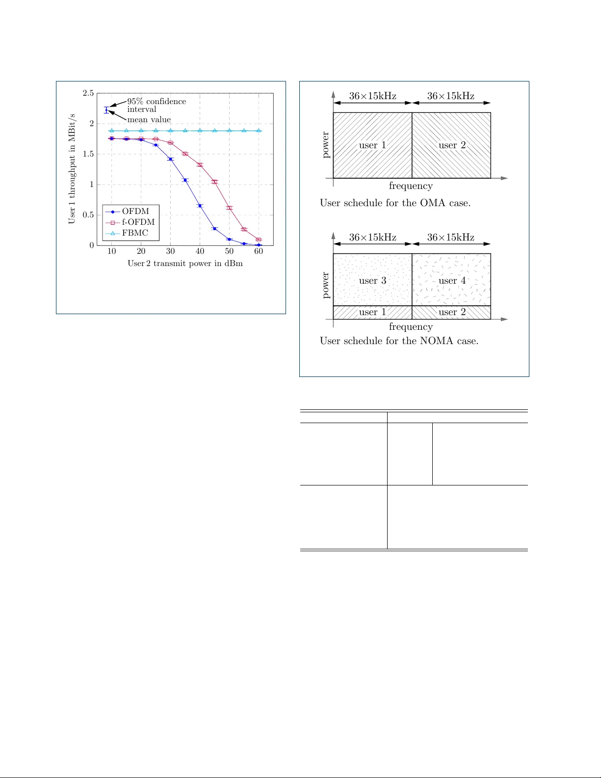
Leave a Comment