Gradient-based Filter Design for the Dual-tree Wavelet Transform
The wavelet transform has seen success when incorporated into neural network architectures, such as in wavelet scattering networks. More recently, it has been shown that the dual-tree complex wavelet transform can provide better representations than …
Authors: Daniel Recoskie, Richard Mann
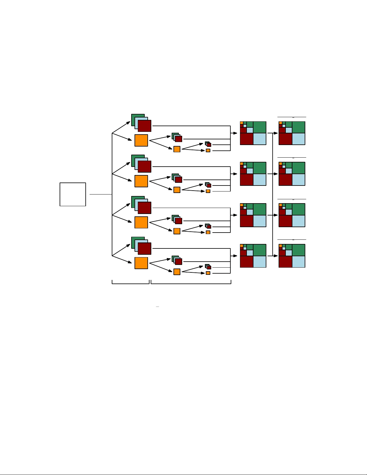
Gradien t-based Filter Design for the Dual-tree W a v elet T ransform Daniel Recoskie ∗ and Ric hard Mann Univ ersity of W aterlo o Cheriton Sc ho ol of Computer Science W aterlo o, Canada { dprecosk, mannr } @u waterloo.ca Abstract The w av elet transform has seen success when incorp orated in to neu- ral netw ork architectures, such as in w av elet scattering netw orks. More recen tly , it has b een shown that the dual-tree complex w av elet transform can provide b etter representations than the standard transform. With this in mind, we extend our previous method for learning filters for the 1D and 2D wa velet transforms in to the dual-tree domain. W e sho w that with few mo difications to our original model, we can learn directional filters that leverage the properties of the dual-tree w av elet transform. 1 In tro duction In this work we explore the task of learning filters for the dual-tree complex w av elet transform [9, 17]. This transform was introduced to address several shortcomings of the separable, real-v alued w av elet transform algorithm. How- ev er, the dual-tree transform requires greater care when designing filters. The added complexit y mak es the transform a go od candidate to replace the tradi- tional filter deriv ations with learning. W e demonstrate that it is p ossible to learn filters for the dual-tree c ompl ex wa v elet transform in a similar fashion to [16, 15]. W e sho w that very few changes to the original auto encoder framew ork are necessary to learn filters that o vercome the limitations of the separable 2D w av elet transform. W av elet represen tations ha ve been sho wn to perform w ell on a v ariet y of ma- c hine learning tasks. Specifically , wa velet scattering net w orks hav e shown state- of-the-art results despite the fact they use a fixed representation (in contrast to the learned representations of con volutional neural netw orks) [2, 11, 3, 12]. ∗ Thanks to NSER C for funding. 1 Similar work has b een done using oriented bandpass filters in the SOE-Net [6]. More recently , it has b een sho wn that extending this work using the dual-tree complex w av elet transform can lead to impro ved results [18, 19]. In all of these examples, the filters used in the net works are fixed. Building upon our work in [16, 15], the goal of this work is to demonstrate that it is possible to learn v alid filters for the dual-tree complex wa velet transform for use in neural netw ork arc hitectures. 2 Problems with the W a velet T ransform The discrete real wa velet transform has man y desirable prop erties, such as a linear time algorithm and basis functions (w av elets) that are not fixed. Ho w- ev er, the transform do es ha ve some dra wbacks. The four ma jor limitations that we will consider are: shift v ariance, oscillations, lac k of directionality , and aliasing. In order to ov ercome these problems, w e will need to make use of com- plex wa velets. W e will restrict ourselves to a single formulation of the complex w av elet transform kno wn as the dual-tree complex wa v elet transform (DTCWT) [9]. The DTCWT ov ercomes the limitations of the standard wa v elet trans- form (with some computational o verhead). Before going into the details of the DTCWT, we will discuss the issues with the standard wa velet transform. A more detailed discussion can b e found in [17]. 2.1 Shift V ariance A ma jor problem with the real-v alued wa velet transform is shift v ariance. A desirable prop ert y for any representation is that small p erturbations of the input should result only in small p erturbations in the feature representation. In the case of the wa velet transform, translating the input (ev en b y a single sample) can result in large c hanges to the w av elet co efficien ts. Figure 1 demonstrates the issue of shift v ariance. W e plot the third scale w a velet coefficients of a signal comp osed of a single step edge. The signal is shifted by a single sample, and the co efficien ts are recomputed. Note that the coefficient v alues c hange significan tly after the shift. 2.2 Oscillations Figure 1 also demonstrates that w av elet co efficien ts are not stable near signal singularities such as step edges or impulses. Note how the wa velet co efficien ts c hange in v alue and sign near the edge. W e can see this problem is more detail b y lo oking at the non-decimated w av elet co efficien ts of the step edge in Figure 2. The co efficien ts necessarily oscillate b ecause the wa velet filter is highpass. 2.3 Lac k of Directionality The standard multidimensional wa v elet transform algorithm makes use of sepa- rable filters. In other w ords, a single one-dimensional filter is applied along each 2 (a) (b) (c) Figure 1: (a) A signal containing a single step edge. (b) The third lev el Daub ec hies 6 wa velet coefficients of (a). (c) Same as (b) but with the signal in (a) shifted by a single sample. (a) (b) Figure 2: (a) A signal containing a single step edge. (b) The (undecimated) third level Daubechies 6 wa velet coeficients corresp onding to the edge. dimension of the input. Though this method lends itself to an efficien t imple- men tation of the algorithm, there are some problems in the impulse resp onses of the filters. Namely , we can only properly achiev e horizontal and v ertical directions of the filters, while the diagonal direction suffers from c heck erb oard artifacts. Figure 3 shows impulse responses of a t ypical wa v elet filter in the 2D transform. The impulse resp onses demonstrate these problems. The problem of not having directionalit y can b e seen b y reconstructing sim- ple images from w av elet co efficien ts at a single scale. Figure 4 sho ws tw o images reconstructed from their fourth scale wa v elet co efficien ts. Note that the hori- zon tal and vertical edges in the first image appear without an y artifacts. The diagonal edges, on the other hand, hav e significan t irregularities. The curved image illustrates this further, as almost all edges are off-axis. 2.4 Aliasing The final problem we w i ll discuss is aliasing. The standard decimating discrete w av elet transform algorithm downsamples the w av elet co efficien ts b y a factor of t wo after the wa velet filters are applied. Normally we must apply a lowpass 3 Figure 3: T ypical impulse resp onse of filters used in the 2D w av elet transform. (a) (b) Figure 4: (a) Left: An image with three edge orientations. Righ t: Reconstruc- tion of the image using only the fourth band Daub ec hies 2 w av elet co efficien ts. Note the irregularities on the edges that are not axis-aligned. (b) Same as (a), but using an image with a curved edge. (an tialiasing) filter prior to downsampling a signal to preven t aliasing. Aliasing o ccurs when downsampling is p erformed on a signal that contains frequencies ab o ve the Nyquist rate. The energy of these high frequencies is reflected onto the lo w frequency comp onen ts, causing artifacts. The wa v elet transform av oids aliasing by careful construction of the wa velet filter. Thus, the original signal can b e p erfectly reconstructed from the do wnsampled w av elet coefficients. Ho wev er, an y c hanges made to the wa velet co efficien ts prior to p erforming the in verse transform (suc h as quantization) can cause aliasing in the reconstructed signal. Figure 5 shows the effects of quantization of a simple 1D signal. In the first case, quan tization is p erformed in the sample domain, leading to step edges in the signal. In the second case, a one lev el wa velet transform is first applied to the signal. Quantization is then performed on the wa v elet coefficients prior to reconstruction. This second metho d of quantization introduces artifacts that did not o ccur when quantizing in the sample domain. 4 (a) (b) (c) Figure 5: (a) Original signal. (b) The signal from (a) quantized to nine levels. (c) A one level w av elet transform is first applied to (a), the wa v elet co efficien ts are quantized to nine levels, and an inv erse transform is applied. Note the artifacts near the step edges. 3 The W a v elet T ransform 3.1 1D W a velet T ransform The wa velet transform is a linear time-frequency transform that was introduced b y Haar [5]. It mak es use of a dictionary of functions that are lo calized in time and frequency . These functions, called wa velets, are dilated and shifted versions of a single mother w av elet function. Our work will b e restricted to discrete w av elets which are defined as ψ j [ n ] = 1 2 j ψ n 2 j (1) for n, j ∈ Z . W e restrict the wa velets to hav e unit norm and zero mean. Since the wa velet functions are bandpass, w e require the introduction of a scaling func- tion, φ , so that we can can cov er all frequencies down to zero. The magnitude of the F ourier transform of the scaling function is set so that [10] | ˆ φ ( ω ) | 2 = Z + ∞ 1 | ˆ ψ ( sω ) | 2 s ds. (2) Supp ose x is a discrete, uniformly sampled signal of length N . The w av elet co efficien ts are computed by con volving eac h of the w av elet functions with x . The discrete wa velet transform is defined as W x [ n, 2 j ] = N − 1 X m =0 x [ m ] ψ j [ m − n ] . (3) The discrete wa velet transform is computed by wa y of an efficient iterative algorithm. The algorithm mak es use of only tw o filters in order to compute all the wa v elet co efficien ts from Equation 3. The first filter, h [ n ] = 1 √ 2 φ t 2 , φ ( t − n ) (4) 5 is called the scaling (lowpass) filter. The second filter, g [ n ] = 1 √ 2 ψ t 2 , φ ( t − n ) (5) is called the wa velet (highpass) filter. Eac h iteration of the algorithm computes the following, a j +1 [ p ] = + ∞ X n = −∞ h [ n − 2 p ] a j [ n ] (6) d j +1 [ p ] = + ∞ X n = −∞ g [ n − 2 p ] a j [ n ] (7) with a 0 = x . The detail co efficien ts, d j , corresp ond exactly to the wa velet co efficien ts in Equation 3. The appro ximation co efficien ts, a j , are successiv ely blurred v ersions of the original signal. The co efficien ts are downsampled by a factor of tw o after each iteration. If the wa velet and scaling functions are orthogonal, we can reconstruct the signal according to a j [ p ] = + ∞ X n = −∞ h [ p − 2 n ] a j +1 [ n ] + + ∞ X n = −∞ g [ p − 2 n ] d j +1 [ n ] (8) The co efficien ts must b e upsampled at eac h iteration b y inserting zeros at even indices. The reconstruction is called the inv erse discrete w av elet transform. 3.2 2D W a velet T ransform In order to process 2D signals, such as images, we must use a mo dified version of the w av elet transform that can b e applied to multidimensional signals. The simplest modification is to apply the filters separately along eac h dimension [14]. Figure 6a sho ws the coefficients computed for a single iteration of the algorithm, where the input is an image. Let us define the following four co efficien t comp onen ts appro ximation: LR ( LC ( x )) (9) detail horizontal: LR ( H C ( x )) (10) detail vertical: H R ( LC ( x )) (11) detail diagonal: H R ( H C ( x )) (12) where LR and H R corresp ond to conv olving the scaling and wa v elet filters re- sp ectiv ely along the rows. W e can define LC and H C similarly for the columns. 6 lowpass rows lowpass columns highpass columns lowpass columns highpass rows highpass columns LR LC LR HC HR LC HR HC - approximation co e ffi cien ts - detail coe ffi cients (a) LR LC HR HC LR HC LR HC LR HC HR LC HR HC HR LC HR LC HR HC (b) Figure 6: (a) One iteration of the 2D discrete wa velet transform. (b) Typical arrangemen t of the wa velet coefficients after three iterations of the algorithm. A t eac h iteration of the algorithm, we compute the appro ximation co efficien ts from Equation 9 and the three detail coefficient comp onen ts from Equations 10 – 12. Like in the 1D case, the co efficien ts are subsampled after eac h conv o- lution. The co efficien ts are t ypically arranged as in Figure 6b. Performing the 2D wa v elet transform in this manner is used in the JPEG2000 standard [4]. 3.3 Dual-T ree Complex W av elet T ransform The problems with the standard w av elet transform discussed in the previous section can b e ov ercome with the DTCWT [17] (see Figures 7, 8, and 9). W e will restrict our discussion to the 2D version of the transform. As its name suggests, the dual-tree w av elet transform mak es use of multiple computational trees. The trees each use a different wa velet and scaling filter pair. W e will b egin our discussion with the real v ersion of the dual-tree transform. Let us denote the filters h i and g i , where i = 1 for the first tree and i = 2 for the second tree. The dual-tree algorithm pro ceeds similarly to the 2D version. Lik e in the 2D case, w e compute four comp onen ts of co efficien ts for eac h tree: LR i ( LC i ( x )), LR i ( H C i ( x )), H R i ( LC i ( x )), and H R i ( H C i ( x )). Each tree com- putes its own co efficien t matrix W i . The final co efficien t matrices are computed as follows: W 1 ← W 1 ( x ) + W 2 ( x ) √ 2 (13) W 2 ← W 1 ( x ) − W 2 ( x ) √ 2 (14) W e therefore ha ve six bands of detail co efficien ts at each level of the transform, as opp osed to three in the 2D case. Example impulse resp onses for real filters 7 is shown in Figure 13a. Note that they are oriented along six differen t direc- tions and there is no chec kerboard effect. The drawbac k of the real dual-tree transform is that it is not approximately shift inv ariant [17]. The complex transform is similarly computed. The main difference is that there are a total of four trees instead of t wo (for a total of tw elv e detail bands). The tw elv e bands are of the form LR i ( H C j ( x )) , H R i ( LC j ( x )) , H R i ( H C j ( x )) (15) for i, j ∈ { 1 , 2 } . Let W i,j represen t the three bands of detail coefficients using filter i for the rows and filter j for the columns. The final complex detail co efficien ts are computed as: W 1 , 1 ← W 1 , 1 ( x ) + W 2 , 2 ( x ) √ 2 (16) W 2 , 2 ← W 1 , 1 ( x ) − W 2 , 2 ( x ) √ 2 (17) W 1 , 2 ← W 1 , 2 ( x ) + W 2 , 1 ( x ) √ 2 (18) W 2 , 1 ← W 1 , 2 ( x ) − W 2 , 1 ( x ) √ 2 (19) In this work we will fo cus on q -shift filters [17]. That is, we restrict h 2 [ n ] = h 1 [ − n ] . (20) In other w ords, the filters used in the second tree are the reverse of the filters used in the first tree. F urthermore, the filters used in the first iteration of the algorithm m ust b e differen t than the filters used for the remaining iterations [17]. The initial filters must also ob ey the q -shift prop ert y , but b e offset by one sample. W e will denote these filters using a prime symbol (e.g., h 0 i is the initial filter in the i th tree). Finally , we restrict ourselves to quadrature mirror filters, i.e., g [ n ] = ( − 1) n h [ − n ] . (21) Th us, we can deriv e the w av elet filters directly from the scaling filter b y re- v ersing it and negating alternating indices. Equations 20 and 21 mean w e can completely define the transform with the filters h 1 and h 0 1 . 4 The W a v elet T ransform as a Neural Net w ork The dual-tree w av elet transform is computed using tw o main op erations: con- v olution and do wnsampling. These tw o op erations are the same as those used in traditional con volutional neural netw orks (CNNs). With this observ ation in mind, we prop ose framing the dual-tree wa v elet transform as a mo dified CNN 8 (a) (b) (c) Figure 7: (a) A signal containing a single step edge. (b) The magnitude of the third level DTCWT coefficients of (a). (c) Same as (b) but with the signal in (a) shifted by a single sample. (a) (b) Figure 8: (a) Left: An image with three edge orientations. Righ t: Reconstruc- tion of the image using only the fourth band DTCWT co efficien ts. (a) (b) (c) Figure 9: (a) Original signal. (b) The signal from (a) quantized to nine levels. (c) A one lev el DTCWT is first applied to (a), the wa v elet co efficien ts are quan tized to nine lev els, and an in v erse transform is applied. Note how the artifacts are muc h le ss pronounced. arc hitecture. See Figures 10 and 11 for illustrations of the real and complex v er- sions of the net work resp ectiv ely . This net work directly implements the wa velet transform algorithm, with eac h la yer represen ting a single iteration. The output of the netw ork are the wa velet co efficien ts of the input image. T o demonstrate how this mo del b eha v es, w e construct an autoenco der frame- w ork [7] consisting of a dual-tree wa velet netw ork follow ed by an inv erse net work. 9 W 1 ( x ) W 2 ( x ) W 1 ( x )+ W 2 ( x ) p 2 W 1 ( x ) W 2 ( x ) p 2 initial fi lter pair second fi lter pair Figure 10: The real dual-tree w av elet transform net work. Eac h W 1 and W 2 are computed as in Equations 13 and 14. W i;j ( x ) initial fi lter pair second fi lter pair fi lter i along rows fi lter j along columns W i;j ( x ) initial fi lter pair second fi lter pair fi lter i along rows fi lter j along columns W 1 ; 1 ( x ) W 1 ; 2 ( x ) W 2 ; 1 ( x ) W 2 ; 2 ( x ) ± Figure 11: The complex dual-tree wa velet transform net work. Each W i,j is computed as in Equations 16 – 19. The in termediate representation in the auto encoder are exactly the wa velet co- efficien ts of the input image. W e will imp ose a sparsit y constrain t on the wa velet co efficien ts so that the mo del will learn filters that can summarize the structure of the training set. In order for our learned filters to compute a v alid wa velet transform, we use the following constrain ts on the filters [16]: L w ( h ) = ( || h || 2 − 1) 2 + ( µ h − √ 2 /k ) 2 + µ 2 g (22) where µ h and µ g are the means of the scaling and w av elet filters resp ectiv ely . The first t wo terms are necessary so that the scaling function will hav e unit L 2 norm and finite L 1 norm [13, 10]. The third term requires that the w av elet filter has zero mean. In order to av oid degenerate filters, w e will require an additional loss term. W e desire filters that will giv e lo calized and cen tered impulse resp onses. There- fore, w e prop ose a loss that prefers impulse resp onses that are close to Gaussian. Let M k b e the matrix corresp onding to the magnitude of the impulse resp onse for the k th band (i.e. the sum of the squares of the real and imaginary impulse 10 resp onses). And let G b e a circular Gaussian matrix of the form: G i,j = αe − [( i − i o ) 2 +( j − j 0 ) 2 ] / (2 σ 2 ) (23) with i 0 and j 0 c hosen to cen ter the Gaussian in the matrix. The new loss term is of the form L g = 6 X k =1 || G − M k || 2 2 (24) W e will learn the netw ork parameters using gradient descent, and so must define a loss function ov er a dataset of images X = { x 1 , x 2 , . . . x M } : L ( X ; h 1 , h 0 1 ) = 1 M M X k =1 || x k − ˆ x k || 2 2 + λ 1 1 M M X k =1 X i,j || W i,j ( x k ) || 1 + λ 2 [ L w ( h 1 ) + L w ( h 0 1 )] + λ 3 L g (25) where ˆ x k is the reconstruction of the auto encoder. W e use mean squared error for our reconstruction loss and the L 1 norm for the sparsity p enalt y . The λ parameters control the trade-off b et ween the loss terms. F or the real v alued net work, the index j is remov ed from the sparsit y summation. 5 Exp erimen ts W e make use of synthetic images to demonstrate that our mo del is able to learn filters with localized directional structure. The generation pro cess is the same one used in [15], but with a restriction to sine wa ves. The pro cess extends the syn thetic generation pro cess for 1D data from [16]: x ( t ) = K − 1 X k =0 a k · sin (2 k t + φ k ) (26) where φ k ∈ [0 , 2 π ] and a k ∈ { 0 , 1 } are chosen uniformly at random. In Equation 26, φ k is a phase offset and a k is an indicator v ariable that determines whether a particular harmonic is presen t. W e fix the size of the images to b e 128 × 128. Figure 12 shows some example syn thetic images. W e set λ 1 = . 1, λ 2 = 1, λ 3 = 4e-5 (real netw ork), and λ 3 = 4e-4 (complex net work). F or the L g cost, we compute the impulse resp onse at the fourth scale and set α = . 02 and σ = 10 (found empirically). W e train using sto c hastic gradien t descent using the Adam algorithm [8]. Our implementation is done using T ensorflo w [1]. Figure 13 shows the impulse resp onses of the filters learned by our real and complex mo dels. In this case, all filters w ere of length ten. W e can see that 11 Figure 12: Examples of synthetic images. (a) Real transform (b) Complex transform Figure 13: Example impulse responses of filters learned using our (a) real and (b) complex mo d el. The top and b ottom ro ws of (b) corresp ond to the real and complex parts of the filter responses resp ectiv ely . the mo del is able to learn lo calized, directional filters from the data. Figure 14 sho ws a comparison of the learned h filter from Figure 13b to Kingsbury’s Q-shift filters. Note that h has a v ery similar structure. The shifted cosine distance measure used in [16] is sho wn ab o ve each plot. See the app endix for more filters and plots. The Gaussian loss term is important for learning directional filters. Figure 15 sho w a selection of filters learned without the impulse response loss term (i.e. λ 3 = 0 in Equation 25). W e can see that the filters are no longer directional, and share similar structure to the impulse resp onses from Figure 3. 6 Conclusion W e presen ted a model based on the dual-tree complex w av elet transform that is capable of learning directional filters that ov ercome the limitations of the standard 2D w a velet transform. W e made use of an autoenco der framework, and constrained our loss function to fav our orthogonal w av elet filters that produced sparse representations. This w ork builds upon our previous w ork on the 1D and 2D wa velet transform. W e prop ose this metho d as an alternative to the traditional filter design metho ds used in wa velet theory . 12 2 4 6 8 10 -0.2 0 0.2 0.4 0.6 0.8 Q-shift learned distance: 2.135335e-03 (a) 2 4 6 8 10 -0.2 0 0.2 0.4 0.6 0.8 Q-shift learned distance: 4.239467e-03 (b) Figure 14: Comparison of Kingsbury’s Q-shift (a) 6 tap, and (b) 10 tap filters with the learned h filter from Figure 13b. Note that h has b een reversed. (a) (b) (c) (d) Figure 15: Example impulse responses of filters learned using our (a,c) real and (b,d) complex mo del without the impulse resp onse loss term (i.e. λ 3 = 0). References [1] Mart ´ ın Abadi et al. T ensorFlow: Large-scale machine learning on hetero- geneous systems, 2015. Softw are a v ailable from tensorflo w.org. [2] Joan Bruna and St ´ ephane Mallat. Classification with scattering op era- tors. In Computer Vision and Pattern R e c o gnition (CVPR), 2011 IEEE Confer enc e on , pages 1561–1566. IEEE, 2011. 13 [3] Joan Bruna and St´ ephane Mallat. In v arian t scattering con volution net- w orks. IEEE tr ansactions on p attern analysis and machine intel ligenc e , 35(8):1872–1886, 2013. [4] Charilaos Christop oulos, A thanassios Sk o dras, and T ouradj Ebrahimi. The jp eg2000 still image coding system: an ov erview. IEEE tr ansactions on c onsumer ele ctr onics , 46(4):1103–1127, 2000. [5] Alfred Haar. Zur theorie der orthogonalen funktionensysteme. Mathema- tische Annalen , 69(3):331–371, 1910. [6] Isma Hadji and Richard P Wildes. A spatiotemp oral oriented energy net- w ork for dynamic texture recognition. In Pr o c e e dings of the IEEE Con- fer enc e on Computer Vision and Pattern R e c o gnition , pages 3066–3074, 2017. [7] Geoffrey E Hinton and Ruslan R Salakhutdino v. Reducing the dimension- alit y of data with neural netw orks. scienc e , 313(5786):504–507, 2006. [8] Diederik Kingma and Jimmy Ba. Adam: A metho d for sto c hastic opti- mization. arXiv pr eprint arXiv:1412.6980 , 2014. [9] Nick Kingsbury . The dual-tree complex wa velet transform: a new efficient to ol for image restoration and enhancement. In Signal Pr o c essing Confer- enc e (EUSIPCO 1998), 9th Eur op e an , pages 1–4. IEEE, 1998. [10] St´ ephane Mallat. A Wavelet T our of Signal Pr o c essing, Thir d Edition: The Sp arse Way . Academic Press, 3rd edition, 2008. [11] St´ ephane Mallat. Group inv ariant scattering. Communic ations on Pur e and Applie d Mathematics , 65(10):1331–1398, 2012. [12] St´ ephane Mallat. Understanding deep conv olutional netw orks. Phil. T r ans. R. So c. A , 374(2065):20150203, 2016. [13] Stephane G Mallat. Multiresolution appro ximations and wa velet orthonor- mal bases of L 2 ( R ). T r ansactions of the A meric an mathematic al so ciety , 315(1):69–87, 1989. [14] Stephane G Mallat. A theory for multiresolution signal decomp osition: the w av elet represen tation. IEEE tr ansactions on p attern analysis and machine intel ligenc e , 11(7):674–693, 1989. [15] Daniel Recoskie and Ric hard Mann. Learning filters for the 2D wa velet transform. In Computer and R ob ot Vision (CR V), 2018 15th Confer enc e on , pages 1–7. IEEE, 2018. [16] Daniel Recoskie and Ric hard Mann. Learning sparse w av elet representa- tions. arXiv pr eprint arXiv:1802.02961 , 2018. 14 [17] Iv an W Selesnick, Richard G Baraniuk, and Nic k C Kingsbury . The dual-tree complex w av elet transform. IEEE signal pr o c essing magazine , 22(6):123–151, 2005. [18] Amarjot Singh and Nic k Kingsbury . Dual-tree w av elet scattering net work with parametric log transformation for ob ject classification. In A c oustics, Sp e e ch and Signal Pr o c essing (ICASSP), 2017 IEEE International Confer- enc e on , pages 2622–2626. IEEE, 2017. [19] Amarjot Singh and Nic k Kingsbury . Efficient conv olutional netw ork learn- ing using parametric log based dual-tree wa velet scatternet. In Pr o c e e d- ings of the IEEE Confer enc e on Computer Vision and Pattern R e c o gnition , pages 1140–1147, 2017. 15 App endix A Learned Filter V alues W e include the learned filter v alues from Figures 15 and 13. A.1 Real dual-tree filters h 0 1 h 1 +7 . 538e-04 +3 . 207e-02 − 6 . 960e-02 − 4 . 052e-03 − 4 . 274e-02 − 5 . 705e-02 +4 . 233e-01 +2 . 732e-01 +7 . 917e-01 +7 . 357e-01 +4 . 234e-01 +5 . 615e-01 − 4 . 291e-02 +5 . 348e-03 − 6 . 972e-02 − 1 . 456e-01 +2 . 573e-04 − 5 . 864e-03 +4 . 025e-04 +2 . 406e-02 Filters from Figure 13a 2. h 0 1 h 1 − 1 . 010e-02 +1 . 970e-02 +3 . 534e-02 − 3 . 822e-02 +2 . 407e-02 − 1 . 078e-01 − 8 . 123e-02 +2 . 241e-01 +2 . 722e-01 +7 . 332e-01 +7 . 981e-01 +6 . 144e-01 +5 . 143e-01 +5 . 249e-02 − 4 . 624e-02 − 1 . 302e-01 − 9 . 701e-02 +9 . 322e-03 − 5 . 738e-04 +3 . 693e-02 Filters from Figure 15a. h 0 1 h 1 +1 . 956e-02 +1 . 970e-02 − 5 . 031e-02 − 3 . 822e-02 − 7 . 082e-02 − 1 . 078e-01 +4 . 035e-01 +2 . 241e-01 +8 . 096e-01 +7 . 332e-01 +4 . 028e-01 +6 . 144e-01 − 7 . 107e-02 +5 . 249e-02 − 4 . 922e-02 − 1 . 302e-01 +1 . 958e-02 +9 . 322e-03 − 1 . 094e-05 +3 . 693e-02 Filters from Figure 15c. 2 4 6 8 10 -0.2 0 0.2 0.4 0.6 0.8 Q-shift learned distance: 2.548161e-03 (a) 2 4 6 8 10 -0.2 0 0.2 0.4 0.6 0.8 Q-shift learned distance: 3.496355e-03 (b) Figure 16: Comparison of Kingsbury’s Q-shift (a) 6 tap, and (b) 10 tap filters with the learned h filter from Figure 13a. 16 A.2 Complex dual-tree filters h 0 1 h 1 +1 . 017e-02 +1 . 914e-02 +3 . 677e-02 − 1 . 947e-02 − 3 . 689e-02 − 1 . 469e-01 − 5 . 913e-02 +3 . 960e-02 +3 . 982e-01 +6 . 020e-01 +8 . 018e-01 +7 . 357e-01 +4 . 223e-01 +2 . 393e-01 − 7 . 171e-02 − 8 . 599e-02 − 8 . 616e-02 − 5 . 614e-03 +4 . 248e-05 +3 . 850e-02 Filters from Figure 13b. h 0 1 h 1 +1 . 523e-02 +2 . 826e-02 − 5 . 440e-02 − 1 . 266e-02 − 6 . 360e-02 − 1 . 225e-01 +4 . 075e-01 +1 . 364e-01 +8 . 054e-01 +6 . 800e-01 +4 . 075e-01 +6 . 807e-01 − 6 . 346e-02 +1 . 358e-01 − 5 . 442e-02 − 1 . 220e-01 +1 . 547e-02 − 1 . 340e-02 +1 . 666e-04 +2 . 921e-02 Filters from Figure 15b. h 0 1 h 1 +1 . 903e-02 − 8 . 475e-02 − 4 . 904e-02 − 8 . 946e-02 − 7 . 057e-02 +3 . 345e-01 +4 . 024e-01 +7 . 659e-01 +8 . 090e-01 +5 . 145e-01 +4 . 020e-01 − 1 . 701e-02 − 7 . 052e-02 − 9 . 557e-02 − 4 . 888e-02 +5 . 711e-02 +1 . 931e-02 +3 . 971e-02 +5 . 240e-04 − 9 . 468e-03 Filters from Figure 15d. 2 4 6 8 10 -0.2 0 0.2 0.4 0.6 0.8 Q-shift learned distance: 2.135335e-03 (a) 2 4 6 8 10 -0.2 0 0.2 0.4 0.6 0.8 Q-shift learned distance: 4.239467e-03 (b) Figure 17: Comparison of Kingsbury’s Q-shift (a) 6 tap, and (b) 10 tap filters with the learned h filter from Figure 13b. Note that h has b een reversed. 17 h 0 1 h 1 +1 . 640e-02 − 1 . 571e-03 − 5 . 179e-02 − 2 . 007e-03 − 6 . 775e-02 +2 . 725e-02 +4 . 049e-01 − 2 . 220e-03 +8 . 068e-01 − 1 . 437e-01 +4 . 050e-01 +2 . 654e-03 − 1 . 189e-01 +5 . 598e-01 +1 . 654e-02 +7 . 526e-01 +3 . 910e-04 +2 . 865e-01 − 7 . 620e-02 − 2 . 374e-02 +3 . 958e-02 +2 . 277e-03 − 7 . 738e-03 Learned length 10 h 0 and length 14 h filters. 2 4 6 8 10 12 14 -0.2 0 0.2 0.4 0.6 0.8 Q-shift learned distance: 2.285723e-03 Figure 18: Comparison of Kingsbury’s Q-shift 14 tap filter with the learned length 14 h . Note that h has b een rev ersed. h 0 1 h 1 +1 . 952e-02 +4 . 335e-04 − 4 . 506e-02 +3 . 752e-04 − 6 . 062e-02 − 6 . 027e-03 +4 . 069e-01 +3 . 851e-03 +8 . 066e-01 +3 . 955e-02 +4 . 043e-01 − 2 . 870e-02 − 7 . 323e-02 − 8 . 351e-02 − 6 . 027e-02 +2 . 887e-01 +1 . 452e-02 +7 . 560e-01 − 9 . 868e-05 +5 . 569e-01 +3 . 984e-03 − 1 . 344e-01 − 1 . 460e-03 +2 . 056e-02 − 2 . 688e-03 − 5 . 462e-04 − 1 . 798e-03 +5 . 302e-05 Learned length 10 h 0 and length 18 h filters ( λ 3 w as increased to 8e-4). 5 10 15 -0.2 0 0.2 0.4 0.6 0.8 Q-shift learned distance: 1.437532e-03 Figure 19: Comparison of Kingsbury’s Q-shift 18 tap filter with the learned length 18 h . 18 App endix B F ull Dual-tree Complex W a velet T rans- form Net w ork W 2 ; 1 ( x ) W 2 ; 2 ( x ) W 1 ; 2 ( x ) − W 2 ; 1 ( x ) p 2 W 1 ; 1 ( x ) − W 2 ; 2 ( x ) p 2 initial fi lter pair second fi lter pair W 1 ; 1 ( x ) W 1 ; 2 ( x ) W 1 ; 1 ( x )+ W 2 ; 2 ( x ) p 2 W 1 ; 2 ( x )+ W 2 ; 1 ( x ) p 2 (1 ; 1) (1 ; 2) (2 ; 1) (2 ; 2) ( i; j ) - fi lter i along rows, fi lter j along columns Figure 20: The full complex dual-tree wa v elet transform net work. Each W i,j is computed as in Equations 16 – 19. 19
Original Paper
Loading high-quality paper...
Comments & Academic Discussion
Loading comments...
Leave a Comment