Millimeter-Wave NOMA Transmission in Cellular M2M Communications for Internet of Things
Massive connectivity and low latency are two important challenges for the Internet of Things (IoT) to achieve the Quality of Service (QoS) provisions required by the numerous devices it is designed to service. Motivated by these challenges, in the pa…
Authors: Tiejun Lv, Yuyu Ma, Jie Zeng
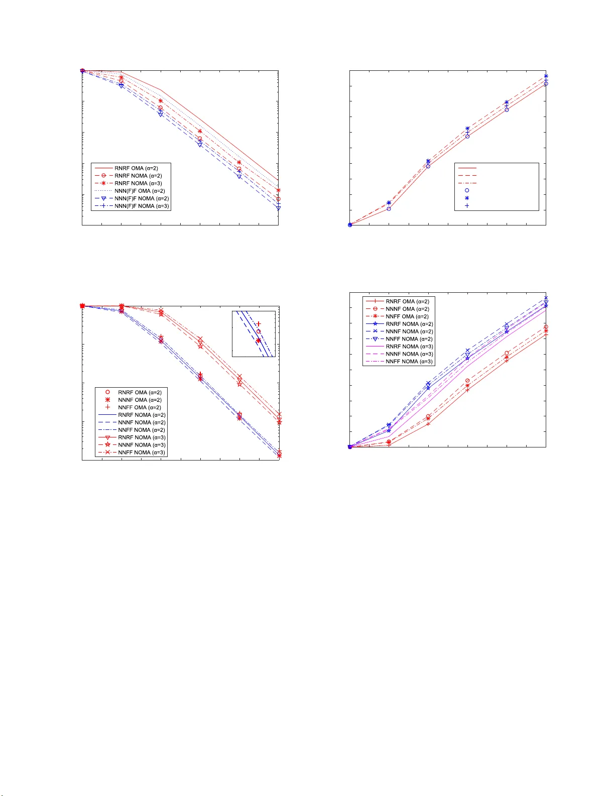
1 Millime ter -W a ve NOMA T ransmission in Cellular M2M Commun icati ons for Internet of Things T iejun Lv , Senior Me mber , IEEE , Y uyu Ma, Jie Zeng , Senior Member , IEEE , and P . T akis Mathiopoulos, S enior Member , IEEE Abstract —Massiv e connectivity and lo w latency ar e tw o impor - tant challenges fo r the Internet of Things (IoT) t o achiev e the Quality of Service (QoS) provisions re quired by t h e numerous devices it is designed to ser vice. Motivated by these challenges, in the paper we introduce a n ew millimeter-wa ve non-orthogonal multiple access (mmW a ve-NOMA) transmission scheme designed fo r cellular machine-to-machine (M2M) communication systems fo r IoT applications. It consists of one base station (BS) and numerous multip le machine type co mmunication (MTC) devices operating in a cellular communication en viro nment. W e consider its down-link perf ormance and a ssume that multiple MTC devices share the same communication resources offered by the proposed mmW a ve-NOMA transmission scheme, wh ich can support m assiv e connectivity . F or this system, a novel MTC pairing scheme is introduced the design of which is based upon the distance between the BS and the M T C devices aiming at reducing t h e system overa ll ov erhead for massiv e conn ectivity and latency . In p articular , we consider th ree differ ent MTC device pairing sch emes, namely i) the rand om near and the random far MTC d evices (RNR F ); ii) the nearest near and the nearest far MTC devices (NNNF); and iii) the n earest near and the f arthest far MT C device ( NN F F). For all three pairing schemes, th eir perf ormance is analyzed by deriving closed-fo rm expressions of th e outage probability an d th e sum rate. Furthermor e, performance comparison studies of the t hree MTC device pairin g schemes hav e been carried out. The va- lidity of the analytical approach has been verified by means of extensive computer simulations. T h e obtained performance ev aluation results hav e d emonstrated that the proposed cellular M2M communication system employing the mmW av e-NOMA transmission scheme impro ves outage probability as compared to equivalent systems using mmW av e wi th Orthogonal Mu ltiple Access (OMA) schemes. Index T erms —Internet of Things (IoT), millimeter - w ave non-orthogonal multip le access (mmW a ve-NOMA), machine-to- machine (M2M), MTC device pairing scheme s, outage probabil- ity . I . I N T RO D U C T I O N Throu g h the development of n umero u s application s, the Internet o f T h ings ( IoT) [ 1], [2] aims at pr oviding a host o f new services to citizens, pr i vate a nd pu blic com panies as well as to governmental administrations [3]–[5]. In gener al, it is en visioned that the IoT will pr ovide a p latform which will The financial support of the National Natural Science Foundati on of China (NSFC) (Grant No. 61671072 ) is gratefully ackno wledged . T . Lv , Y . Ma and J. Zeng are with the School of Information and Communicat ion Engineering , Beijing Univ ersity of P osts and T elecom- municati ons (BUPT), Beijing 100876, China (e-mail: {lvt iejun, mayy , zengji e}@bu pt.edu.cn). P . T . Mathi opoulos is with the Department of Informatic s and T elec ommu- nicat ions, Nationa l and Kapodistrian Uni versity of Athens, Athens 157 84, Greece (e-mail : mathio@di .uoa.gr). connect a huge numb e r of devices in ord er to gathe r , share and fo rward inform a tion b etween devices as well as th e ir users [6]– [8]. It is estimated that by the year 20 20 almo st 50 billion of d evices will connected to this platform [9]. T o accommo date th e dra stically in creasing nu mber of these devices, th e resulting hug e increase in d a ta traffic will h ave a great impact on th e design and implemen tation of 5th Genera- tion (5G) wir eless commu nication systems. In particular, there will b e challenging req uirements for their efficient opera tion, including m assi ve con n ectivity and low latency [10], [11]. On the o n e hand, machine-to -machine (M2 M) comm u nications have been regar d ed as o ne of the pro mising n ew techno logies to realize IoT employing the 5 G network [ 1 2]. M2M c o m- munication systems realize au tomated d ata commu nications among mach ine type commun ication (MTC) devices thus constituting the ba sic commun ication infr astructure f or the emerging IoT [13], [1 4]. In add ition, Long T erm Evolution (L TE) for MTC (L TE-M) and n arrow band IoT (NB-IoT) h av e been pr oposed on top of existing cellular standard s, which can provide reliab le solu tions f or M2M comm unications [15]. On th e oth e r hand, no n-orth ogonal mu ltiple access (N O M A), which h a s been prop osed as a multiple acc e ss sch eme to be employed with 5G wireless commu nication systems, has the ability to support massi ve co nnectivity by means of non- orthog onal reso u rce allocation wh ile simultaneou sly re d ucing latencies by its g rant-fr e e scheduling . For examp le, in [16], an interesting power -domain u ser mu ltiplexing scheme for f u ture radio acc e ss has b een pr o posed. Note th at the superp osition code (SC) at the transm itter side and successive interference cancellation (SIC) at the receiver side are widely co nsidered in the papers with NOMA transmission [1 6]–[20]. As op posed to orth o gonal multiple access (O M A) schemes, NOMA can support m any users via non-o r thogon al re so urce allocation, i.e., multiple users can be served at th e simul- taneously at the time, frequency and code d omains as well as being multiplexed at different power levels [2 1]–[23]. For example, un der po or chan nel co nditions, u sers are a llo cated more transmission power as compar e d to users operating under better chann el co nditions [ 24]–[26]. Such an appro ach clear ly improves the commun ication systems’ overall fairness. It is noted th at since users within one gro up share the av ailable in the g roup com m unication resource s, user gr o uping strategies can significantly influen c e the overall NOMA system per for- mance [2 7], an d thus it is n e cessary to carefully study user scheduling schem es [28]–[3 1]. Due to the h igh d emand of bandwidth required to sup- port sign ifica n tly increased data rates, the use of NOMA to 2 millimeter w a ve (mmW a ve) become s a natural choice for 5G system s [32]–[3 4]. In the past, sev eral studies h av e been carried o ut. For example, the authors of [ 32] pr oposed a cooper a tive m mW ave-NOMA mu lticast scheme to im prove the mmW a ve-NOMA m u lticasting. In [3 3], a p e rforman ce analysis of NOM A in mmW ave cells was provid e d. By con- sidering key features of mmW ave systems, su ch as the h igh directionality of mmW a ve tran smissions, the perfo rmance of the mmW ave-NOMA system was analyzed in [34]. From these and other referenc e s it has b e c ome clear that mmW ave-NOMA transmission ha s the hug e potential f or satisfying the specific requirem ents o f cellular M2 M commu nications b ased IoT . Device-to-Device (D2D) an d M2M comm unications based on m m W ave or NOM A tech nologies have also attracted considerab le attention in both in d ustrial a n d a c a demic com- munities [9], [ 12], [13], [35], [36]. For example in [9] the authors have propo sed a novel architecture of green r e la y assisted D2D co mmunicatio ns with dual batter y for IoT . The capab ility of m mW ave commun ications fo r IoT - c loud supported auton omous vehicles was explore d in [3 5]. A new multiple-inp ut multiple- output ( MIMO) NOMA sch e me for small packet transmissions in IoT , whic h was b ased on some devices that need to be served quickly , w as in vestigated in [36]. The authors in [13] presented an overview of 3GPP solution s for en abling massiv e cellular IoT an d investigated the r andom access stra tegies for M2M c o mmunica tions, wh ich showed that cellular n etworks should furth e r evolve to support massive connectivity an d low laten cy . In [1 5], NOMA was employed to suppo rt a la rge numb e r of d evices in cellular systems with limited radio reso urces. A mmW a ve-NOMA based relaying scheme was prop osed in [37] aiming at su pporting I oT app li- cations. In [12], [38], the author s have studied energy-efficient resource allocation for an M2M enabled cellu lar n etwork. Consequently , the c ombinatio n o f M2M communic a tions and cellular wireless co mmunicatio ns is essential for IoT . This combinatio n, in con ju nction with th e massiv e connec tivity requirem ents of the Io T , sh ould lead to the use of appropriately modified multiple access tech niques. Sinc e in NOMA, a pair of devices share th e same commu nication resour c e, device pairing can p lay a key role in imp roving the performa n ce of NOMA systems. Howe ver, to th e best of our kn owledge, MTC device p airing sch emes h av e not been studied yet in th e o pen technical literatu re. Motiv ated by the above, in this paper we consider a n ovel mmW ave NOMA transmission system for cellular M2 M com- munication s tailored f o r IoT applications. For the efficient operation of th e prop o sed system we effectiv ely pair MTC devices in three schemes accord ing to the ir distances from the base station (BS), as follows: i) Random n ear MTC device and rand o m far MTC d evice ( RNRF), i.e. on e near M T C device and one far MTC device are ran domly selected f rom two d ifferent gr oups; ii) the near est near MTC device and the n earest far MT C device (NNNF), in wh ich the nearest nearMTC d evice and the n e arest far M T C device a re selected from from two different grou ps; iii) the near est near MTC device and the farthest far MTC d evice (NNFF), in which th e nearest near MTC device a n d the farthest far MTC device are selected from two different g roups. The main advantages a n d novelties of the propo sed mmW ave NOMA sch eme can be summarized as follows: • Due to th e high d irectionality of m mW ave and the excellent collision av o idance of NOMA , the pro posed mmW ave-NOMA transmission system is cap able of achieving massi ve connectivity in cellular M2M commu- nications. Further m ore, it is shown that by em ploying random beamf o rming it is not re quired from all MTC devices to provide their chann el state inform ation (CSI) to the BS, which natu rally leads to reduced overhead and latency . • Focusing on a single b e am, we employ the above men- tioned thr ee MTC device pairing schemes which take MTC devices’ loc a tions into accoun t in the mm W av e- NOMA transmission scheme. These pairing schemes do not req u ire the BS to ha ve k nowledge o f th eir CSI, thereby reducing th e system overhead. Mo r eover , tran s- missions o f the MTC devices req uiring different chan nel condition s are easily imp lemented in NOMA so that quality of service ( Q o S) require ments of MTC devices can be ea sily achieved. • Closed-for m expr e ssions of the outag e prob ability and sum rate at near MTC devices a nd far MTC devices are derived for the thr ee prop osed MTC device pairing schemes in cellular M2M commu n ications employing the mmW ave- NOM A transmission sch e me. By analyzing th e perfor mance of all three M TC device pairing schemes, it is th eoretically p r oven tha t among the thr ee pair ing schemes, NNNF achieves the lowest outag e prob ability both for n ear MTC and far MTC de vices. The rest of this paper is organized as follows: Section II describes the pr oposed mmW av e-NOMA transmission scheme in cellular M2M commun ications. Section III deri ves the closed-for m expr essions of outage prob ability and sum rate for the propo sed MTC device p a iring schemes in cellular M2 M commun ications fo r I o T . Section IV presents various per- forman ce ev aluation results obtaine d my m eans of c o mputer simulations as well as related discussion . Finally , conclusion s are provide d in Section V . I I . S Y S T E M M O D E L In this section , we first presen t th e chann el model used in the considered communicatio n system followed by th e detailed description of the p r oposed transm ission scheme. Finally , a detailed deriv ation of the signal-to -interfere n ce-plus-n oise ratio (SINR) for the M TC devices will be presented. A. Chann el Mod el Follo wing [ 39] and [34], a typical mmW av e c h annel con- tains a line-o f -sight (LOS) path and se veral non-line-o f-sight (NLOS) paths. Therefor e , the mmW ave chan nel vector from the BS to MTC device k can be math e matically modeled as h k = √ M α k,L a ( θ k,L ) p 1 + d α L k + √ M L X l =1 α k,N L a θ l k,N L p 1 + d α N L k , (1) 3 where α k,L and θ k,L represent the c o mplex gain and n ormal- ized direction of MTC device k f or the LOS path , respec- ti vely; α k,N L and θ k,N L represent th e complex gain and the normalized dir e ction of MTC device k for the NL OS path, respectively; L is the nu m ber of NLOS paths, and α L and α N L are th e path loss exponents for the LOS and the NLOS path, respectively; d k denotes the distance from th e BS to MTC device k . In addition , a ( θ ) is an arr a y steer in g vector which can be expressed as a ( θ ) = 1 √ M h 1 , e − j π θ , · · · , e − j π ( M − 1) θ i T , (2) where [ · ] T indicates th e transpo se of matrix. In mmW ave commun ic a tio n systems, the effect o f LOS path is d ominant beca u se the path lo ss of NLOS exponents is much larger than that o f the LOS exponen t, e.g . the power of the signal fo llowing the LOS p ath is 20 dB hig her than the power of the signals following the NLOS paths [39]. Consequen tly , the d ominant path is the LOS path if such path exists, o r the dominan t path is one of the NLOS paths if a LOS p a th doesn’t exist. Similar to [39] and [3 4], we ad opt the sin g le-path (SP) model, so that the m mW ave channel simplifies to h k = √ M α k a ( θ k ) p 1 + d α k , (3) where α k is the comp lex gain of MTC device k and follo ws the complex Gaussian distribution with zer o m e an an d variance 1, i.e., α k ∼ C N (0 , 1) ; θ k is th e normalized d irection o f the dominan t p a th for MTC d evice k , and θ k ∼ Unif [ − 1 , 1] , i.e., θ k is unif o rmly distributed between − 1 an d 1 , wh ile α is the path loss exponent. B. mmW ave-NOMA T ransmission Since con ventional bea m formin g requires that all MTC devices provide th eir CSI to the BS, system overhe a d and latency ar e inevitably increased . I n o rder to red uce them , random be amformin g is e m ployed, with each beam serv icing two MTC devices. For simplicity , we focus on a single be a m , which can be applied to multiple- beam case. The single beam is expressed as p = a ( ν ) , (4) which is gener ated b y the BS. In (4) and similar to [39] and [34], ν is a r andom variable with un iformly distributed between − 1 and 1 , i.e., ν ∼ Unif [ − 1 , 1] . Note that a ( ν ) is giv en by (2). According to [39] and [34], th e effective cha n nel gain of the MT C device k , h H k p 2 , can be expressed as h H k p 2 = M | α k | 2 a ( θ k ) H p 2 1 + d α k = | α k | 2 M − 1 P n =0 e − j π n ( ν − θ k ) 2 M (1 + d α k ) = | α k | 2 sin 2 π M ( ν − θ k ) 2 M (1 + d α k ) sin 2 π ( ν − θ k ) 2 = | α k | 2 (1 + d α k ) F M ( ν − θ k ) , (5) BS v D C D R A D R B D R B D A D C A D D R R C A D C A C A R D D Figure 1. The proposed mmW a ve-NOMA downl ink transmission scheme in cellu lar M2M communicati ons for IoT , which include a BS and two groups of MT C de vices, A = { A i } and B = { B j } located in the regi ons D A and D B , respe cti vely , which ha ve a central ang le of 2∆ . Distribut ions of the ne ar MTC devic e (yellow circles) and the far MTC de vice (green circle s) follo w HPPPs. The MTC de vices located in D A and D B will be schedule d. where F M ( · ) is the F ejér kernel . By incr e asing ( ν − θ k ) , F M ( ν − θ k ) goes to zer o q uickly . If the d irection o f chann el vector of MTC device k aligns to the d irection of th e beam p , the MTC device will have a large effecti ve channel gain. Furthermo re, a large n u mber of MTC d evices increase the probab ility of alignment so that massi ve co nnectivity can be more effecti vely supported by using a mmW ave-NOMA transmission schem e. In this pap er , we introdu c e a n ew mmW a ve-NOMA down- link tran smission sch eme design ed for cellu lar M 2M com m u- nications for Io T ap plications fo r wh ich o ne BS serves two group s of MTC devices A = { A i } and B = { B j } , where i = 1 , 2 , · · · , N A and j = 1 , 2 , · · · , N B . N k ( k ∈ { A, B } ) denotes the number of MTC devices in two groups. The BS equippe d with M transmit anten nas is located at th e center of th e cell while each MT C d evice is equipp e d with a sing le antenna. As illustrated in Fig. 1 , and according to the op eration of the prop osed transmission scheme, MTC devices which are located at th e wedge- sh aped sector D A , with a n an gle o f 2∆ and a radius R D A , and at the sector ring D B with a maximum radius R D B and a m in imum radius R D C , are sched uled. It is noted that for the limiting case of ∆ → 0 , a large effecti ve channel gain can be achieved. W e consider the scenario in which th e MTC devices in group A are d eployed within the wedge-sh aped sector D A , and th e devices in grou p B ar e d eployed within the sector ring D B . It is also a ssum ed that R D C ≫ R D A so that the channel con ditions in these two coverage ar eas are different for the two gr oups of MTC devices [40]. It is furth er as- sumed that M T C d evices are r andomly de ployed within the wedge-shap ed sector D A and the sector ring D B , and that they follow a homoge n eous Poisson point pro cess (HPPP) Φ k ( k ∈ { A, B } ) with density λ k . Thus, th e prob ability dis- tribution of N k ( k ∈ { A, B } ) is P ( N k = n ) = µ n k e − µ k /n ! , where µ A = ∆ R 2 D A λ A and µ B = ∆( R 2 D B − R 2 D C ) λ B . As previously mentioned , two MTC d evices are selected to implemen t NOMA, with one of th em belon gs to grou p A a n d th e oth er o ne to grou p B . Fur th ermore, ba sed on the 4 locations of MTC devices, we consider the following three MTC device pairing schem es to per form NOM A: i) RNRF , in which the n ear MTC device a n d the far MTC device are random ly selected from the two gro ups; ii) NNNF , in which the n earest n ear MTC d evice and the nearest far MT C device are selected fro m the two gr oups; and iii) NN FF , in wh ich the nearest near M T C device and the farthest far MTC device ar e selected from the two gro ups. C. SINR o f MTC Devices Let us select one MTC device fr om e a ch o f the two MTC device gr oups, and the two selected MTC devices are p aired to perform NOMA, so that N k ≥ 1 ( k ∈ { A, B } ) . Th e BS broadc a sts the signal p ( β i 1 s A i + β i 2 s B i ) to the near MTC device A i and th e far MTC device B i , wh ere s A i and s B i are the tra nsmit signals of A i and B i , an d β i 1 and β i 2 are th eir power allocations, respectively , with β i 1 < β i 2 , β 2 i 1 + β 2 i 2 = 1 . The received signa l at the MTC device A i is expressed as y A i = h H A i p ( β i 1 s A i + β i 2 s B i ) + n A i , (6) where n A i represents ad ditiv e white complex Gaussian noise (A WGN). Considering SIC at the receiver , the MTC device A i first decodes the signal of B i , so that the SINR of B i at the receiver of A i can b e expressed as SINR B i → A i = ρ h H A i p 2 β 2 i 2 ρ h H A i p 2 β 2 i 1 + 1 , (7) where ρ deno tes the transmit signal-to -noise ratio (SNR). Then, A i decodes its own signal, so the SNR o f A i is expressed as SINR A i = ρ h H A i p 2 β 2 i 1 . (8) Similarly , since the MTC device B i decodes its own signal by treatin g th e signal of MTC d evice A i as noise, the SINR of B i is expressed as SINR B i = ρ h H B i p 2 β 2 i 2 ρ h H B i p 2 β 2 i 1 + 1 . (9) I I I . P E R F O R M A N C E A N A L Y S I S O F T H E M T C D E V I C E P A I R I N G S C H E M E S T o gua rantee the QoS requir e d by the MTC d evices, we define R 1 and R 2 as the min im um sum rate of the near MTC device an d the far MTC de vice, respectively , and that ǫ A i = 2 R 1 − 1 an d ǫ B i = 2 R 2 − 1 . When th e near MT C device A i cannot decode su ccessfully the sign al of the far MTC device B i nor its own signal, outage o f the MTC device A i occurs with the following pro bability P o A i = 1 − P (SINR B i → A i > ǫ B i , SINR A i > ǫ A i ) . (10) Furthermo re, the o utage prob ability of MTC device B i is formu late d as P o B i = P ( SINR B i < ǫ B i ) . (11) Using (10) and ( 11), the ou ta g e sum rate of cellular M2M com m unication s with the mmW av e-NOMA transmis- sion scheme c an b e expressed as R NOMA = 1 − P o A i R A i + 1 − P o B i R B i , (12) while the eq uiv a lent outage sum rate of cellu lar M2M comm u- nications with the mmW ave-OMA transmission scheme can be expressed as R OMA = (1 − P A i ) R O A i + (1 − P B i ) R O B i , (13) where P n = P log 1 + ρ h H n p 2 < 2 R O n , n ∈ { A i , B i } , and R O n = 1 2 log 1 + ρ h H n p 2 , n ∈ { A i , B i } . (14) The reason wh y the term 1/2 appea r s in (14) is the fact that the two MTC devices use a resource blo ck, w h ich is shared by two MT C devices in NOMA transmissions [27], [2 8]. Next we will analy ze the p erform ance of th e three MTC device pairin g schemes. A. RNRF P airing S cheme For th is schem e, a near MTC device A i and a far MTC device B i are ran domly selected from the two gr oups with equal prob ability to b e served with th e NOMA protoco l. It is noted that, since the BS does not require any CSI based on random selection of the MTC devices, th e system overhead is significantly redu c ed. 1) Outage Pr obability of the MTC Nea r Device of RNRF: In principle, the ou ta g e p robability can be o btained b y ev alu- ating (1 0) u sin g ( 5), ( 7) and ( 8). However , it is not difficult to realize that this is a very complex task as its solution in v olves a non-d eterministic polyno mial-time h ard problem. I nstead, we will co nsider the limiting cases fo r ∆ → 0 and high SNR to obtain th e ou tage p robab ility perfo r mance. For this, the following theo rem will be used to obtain the o u tage probability of the near MTC device of RNRF for arbitrary values of path loss expon e nt, α . Theorem 1. F or ∆ → 0 a nd high SNR, the outage p r ob a bility of th e ne ar MTC device A i of RNRF can be a ppr o ximated as P o A i ≈ η A i M 2 + π 2 M 2 ∆ 2 18 1 2 + R α D A α + 2 , ( 15) if β 2 i 2 − β 2 i 1 ǫ B i > 0 ; oth e rwise P o A i = 1 . In the above eq u ation, η A i = max ǫ B i ρ ( β 2 i 2 − β 2 i 1 ǫ B i ) , ǫ A i ρβ 2 i 1 . Pr oo f: β 2 i 2 − β 2 i 1 ǫ B i ≤ 0 in d icates the near MTC device cannot deco d e th e signal of the far MTC device successfully , hence P o A i = 1 . When β 2 i 2 − β 2 i 1 ǫ B i > 0 , (15) will b e derived as follows. The MTC devices are d eployed in D A following HPPPs, so they are indepe ndently an d identically distributed (i.i.d.) points, d enoted b y W A i , co nsidering the location info rmation 5 A i . Th erefore , the p robability density function (PDF) of W A i can be expressed a s f W A i ( w A i ) = λ A µ A = 1 ∆ R 2 D A . (16) Then, the o utage p robability of the near MTC device A i is giv en by P o A i = Z D A 1 − e − η A i ( 1+ d α A i ) F M ( v − θ A i ) f W A i ( w A i ) dw A i (17) = 1 ∆ R 2 D A Z ν +∆ ν − ∆ Z R D A 0 (1 − e − η A i ( 1+ r α ) F M ( v − θ ) ) rdr dθ , where η A i = max ǫ B i ρ ( β 2 i 2 − β 2 i 1 ǫ B i ) , ǫ A i ρβ 2 i 1 . Accordin g to (5), the F ejér kernel can be wr itten as F M ( ν − θ ) = sin 2 π M ( ν − θ ) 2 M sin 2 π ( ν − θ ) 2 . (18) Noting tha t | ν − θ | ≤ ∆ , and f ollowing [34], fo r ∆ → 0 , the F ejér kernel can be appro ximated as F M ( ν − θ ) ≈ M sinc 2 π M ( ν − θ ) 2 ≈ M 1 − π 2 M 2 ( ν − θ ) 2 12 ! . (19) In deriving (19) the following approx imations have been used: sin ( x ) ≈ x for x → 0 , sinc ( x ) ≈ 1 − x 2 6 and (1 − x ) 2 ≈ 2 x fo r x → 0 . Therefo re, (17) can be ap proxim ated as P o A i ≈ Z ν +∆ ν − ∆ Z R D A 0 1 ∆ R 2 D A × 1 − e − η A i ( 1+ r α ) M 1 − π 2 M 2 ( ν − θ ) 2 12 rdr dθ ≈ Z ν +∆ ν − ∆ Z R D A 0 1 ∆ R 2 D A × 1 − e − η A i ( 1+ r α ) M 1+ π 2 M 2 ( ν − θ ) 2 12 ! rdr dθ , (20) where the second appr o ximation holds because of (1 − x ) − 1 ≈ (1 + x ) for x → 0 . Additionally , s ince η A i goes to zero at high SNR, (1 − e − x ) ≈ x for x → 0 can be used to appr oximate (20) as P o A i ≈ 1 ∆ R 2 D A Z ν +∆ ν − ∆ Z R D A 0 η A i (1 + r α ) M × 1 + π 2 M 2 ( ν − θ ) 2 12 ! rdr dθ . (21) From (21 ) an d after some straightforward mathematical manipulatio ns, (15) can be easily derived. 2) Outage P r obability of the F ar MTC Device o f RNRF: According to the NOMA principle, the outage of the far MTC device B i appears when it cannot decode its own signal successfully . Again considerin g the limitin g cases f or ∆ → 0 an d high SNR, the following theorem gives the outage probab ility of the far MTC device o f RNRF for ar b itrary values of path loss exponen t, α . Theorem 2. F or ∆ → 0 a nd high SNR, the outage p r ob a bility of the far MTC device B i of RNRF can be appr o ximated a s P o B i ≈ η B i M R 2 D B − R 2 D C 2 + π 2 M 2 ∆ 2 18 × R 2 D B − R 2 D C 2 + R α +2 D B − R α +2 D C ) α + 2 ! , (22) if β 2 i 2 − β 2 i 1 ǫ B i > 0 ; otherwise P o B i = 1 . In ( 22), η B i = ǫ B i ρ ( β 2 i 2 − β 2 i 1 ǫ B i ) . Pr oo f: Similar to the near MTC d evice case, th e far MTC device canno t d e c ode its o wn signal succe ssfully wh en β 2 i 2 − β 2 i 1 ǫ B i ≤ 0 , i.e., P o B i = 1 . Next, the o utage prob ability of the far MTC device will b e derived when β 2 i 2 − β 2 i 1 ǫ B i > 0 . Similar to the near MTC device A i , the PDF of W B i can be expressed as f W B i ( w B i ) = λ B µ B = 1 ∆ R 2 D B − R 2 D C . (23) Therefo re, th e o utage pro b ability of the far MTC device B i is given by P o B i = Z D B (1 − e − η B i ( 1+ d α B i ) F M ( v − θ B i ) ) f W B i ( w B i ) dw B i (24) = 1 ∆( R 2 D B − R 2 D C ) Z ν +∆ ν − ∆ Z R D B R D C (1 − e − η B i ( 1+ r α ) F M ( v − θ ) ) rdr dθ , where η B i = ǫ B i ρ ( β 2 i 2 − β 2 i 1 ǫ B i ) . Follo wing a similar pro cedure as for the near MTC device case, the approxim a tion of (24) can be obtained as P o B i ≈ 1 ∆( R 2 D B − R 2 D C ) Z ν +∆ ν − ∆ Z R D B R D C η B i (1 + r α ) M × 1 + π 2 M 2 ( ν − θ ) 2 12 ! rdr dθ . (25) From (2 5) and after some straightforward mathematical manipulatio ns, (22) ca n be easily derived. B. NNNF P airing S cheme For this scheme, we select a MT C d evice within the wedge- shaped sector D A which has the shortest distance to the BS as the near MTC device A i ∗ . Similarly , we select a MTC device within the sector ring D B which has the shortest distance to the BS as the far MTC device B i ∗ . Becau se of these choices, this schem e can achieve the minimu m ou tage pro bability of both the nea r an d far MTC devices, wh ich can be co nsidered as an u pper bound on th e performa nce. In this case, the BS needs to know only th e MTC devices’ distance infor mation in 6 NNNF , which leads to a lower system overhead as compared to requirin g the k n owledge of the MTC devices’ effecti ve channe l gains. 1) Outage Pr obability of the Nea r MTC device of NNNF: Similar to th e case of RNRF , the outage of the nea r MTC device A i ∗ can occur for two reaso ns. The first o ne is that the n ear MTC device A i ∗ cannot d ecode the signal of the far MTC device B i ∗ successfully , wh ile the seco nd on e is that the ne ar MT C device A i ∗ cannot d ecode its own sign al successfully . Based on these, we can an a lytically o btain the outage pro bability of the near MTC device of NNNF . The following theorem gives the o utage pr o bability of the near MTC d evice of NNNF f or an arb itrary cho ice of path loss exponent, α . Theorem 3. F or ∆ → 0 and h igh SNR, the o utage pr ob a bility of the ne a r MTC device A i ∗ of NNNF can be appr oximated as (26) ( shown at the to p o f page 7), if β 2 i 2 − β 2 i 1 ǫ B i > 0 ; otherwise P o A i ∗ = 1 . In (26), γ ( · ) denotes the in complete gamma fu nction. Pr oo f: Th e near MTC device canno t deco de the sign a l of the far M TC device successfully when β 2 i 2 − β 2 i 1 ǫ B i ≤ 0 , i.e., P o A i ∗ = 1 . Next, the o utage prob ability of the near MTC device will be consider ed when β 2 i 2 − β 2 i 1 ǫ B i > 0 . The distance b etween the near est A i ∗ and the BS is deno ted by d A i ∗ . T h e pro bability Pr ( d A i ∗ > r | N A ≥ 1) c ondition e d on N A ≥ 1 implies that th ere is no device located in the sector with ra d ius r , which is expressed as Pr ( d A i ∗ > r | N A ≥ 1 ) = Pr ( d A i ∗ > r ) − P r ( d A i ∗ > r , N A = 0 ) Pr ( N A ≥ 1) = e − ∆ λ A r 2 − e − ∆ λ A R 2 D A 1 − e − ∆ λ A R 2 D A . (27) According to th e above expression, the location information about A i ∗ can be o btained. Therefore, the PDF of d A i ∗ is gi ven by f d A i ∗ ( r A ) = 2∆ λ A r A 1 − e − ∆ λ A R 2 D A e − ∆ λ A r 2 A . (28) Next, the outag e prob ability of the n earest near MTC device A i ∗ is given by P o A i ∗ = Z ν +∆ ν − ∆ Z R D A 0 1 − e − η A i ( 1+ r α ) F M ( v − θ ) f d A i ∗ ( r ) 2∆ drdθ . (29) Similar to the near MTC device A i of RNRF , ( 29) can be approx imated as P o A i ∗ ≈ Z ν +∆ ν − ∆ Z R D A 0 η A i (1 + r α ) M × 1 + π 2 M 2 ( v − θ ) 2 12 ! f d A i ∗ ( r ) 2∆ drdθ . (30) From (3 0) and after som e some straigh tforward ma th emat- ical man ipulations, (26) ca n be easily derived. 2) Outage Pr obability of the F ar MTC d evice of NNNF: Similar to the far MTC device of RNRF , the ou ta g e of the far M TC device B i ∗ occurs for one situation , namely when the far MTC device B i ∗ cannot deco de its own signal successfully . This case character izes the o ccurren ce of the outage pro bability for the far MTC which ca n b e obtained for an arb itrary choice of path loss exponen t, α , th r ough the following the o rem. Theorem 4. F or ∆ → 0 a nd high SNR, the outage p r ob a bility of the far MTC device B i ∗ of NNNF c a n be a ppr oximated as (31) (shown at the to p of pag e 6) if β 2 i 2 − β 2 i 1 ǫ B i > 0 ; otherwise P o B i ∗ = 1 . Pr oo f: The far MTC device can not d ecode its own signal successfully when β 2 i 2 − β 2 i 1 ǫ B i ≤ 0 , i.e., P o B i ∗ = 1 . When β 2 i 2 − β 2 i 1 ǫ B i > 0 th e outage probab ility of the far MTC device will be o btained next. The distance b etween the nearest B i ∗ and the BS is denoted by d B i ∗ . Similar to (28), the PDF o f d B i ∗ is expr essed as f d B i ∗ ( r B ) = 2∆ λ B r B 1 − e − ∆ λ B R 2 D B − R 2 D C e − ∆ λ B ( r 2 B − R 2 D C ) . (32) Then, the outage pro bability o f the near e st far MTC device B i ∗ is g iv en b y P o B i ∗ = Z ν +∆ ν − ∆ Z R D B R D C 1 − e − η B i ( 1+ r α ) F M ( v − θ ) f d B i ∗ ( r ) 2∆ drdθ . (33) Similar to (21), (33) can be app roximated as P o B i ∗ ≈ Z ν +∆ ν − ∆ Z R D B R D C η B i (1 + r α ) M × 1 + π 2 M 2 ( v − θ ) 2 12 ! f d B i ∗ ( r ) 2∆ drdθ . (34) From (3 4) and after some straightforward mathematical manipulatio ns, (31) ca n be easily derived. C. NNFF P airing S cheme For this scheme, we select, with in the sector D A , a MTC device whic h has the shortest distance to the BS as the n e a r MTC device A i ′ . Similarly , we select a MTC d evice within the sector r ing D B which has th e farthest distance to the BS as the far MTC device B i ′ . If MTC device channel conditions are bigger differences, NOMA can achieve a larger performan ce gain over OMA, which leads to the NNFF MTC de vice pairing scheme. 1) Outage Pr obability of the Near MTC device o f NNFF: As for the N N NF case, he re also the n ear MTC device is selected in the same way . In addition , their power allocation factors ar e identical. The refore, outage pr obability of the n e ar MTC de vice A i ′ is the same as the outage pr o bability o f A i ∗ of NNNF . The appro x imation of its outag e probability expression is given by (2 6), and the proof is the sam e as that of the Theorem 3. 7 P o A i ∗ ≈ η A i λ A M 1 − e − ∆ λ A R 2 D A 2∆ + π 2 M 2 ∆ 3 18 1 − e − ∆ λ A R 2 D A 2∆ λ A + (∆ λ A ) − α +2 2 2 γ α 2 + 1 , ∆ λ A R 2 D A ! . (26) P o B i ∗ ≈ η B i λ B M 1 − e − ∆ λ B R 2 D B − R 2 D C 2∆ + π 2 M 2 ∆ 3 18 e ∆ λ B R 2 D C × e − ∆ λ B R 2 D C − e − ∆ λ B R 2 D B 2∆ λ B + (∆ λ B ) − α +2 2 2 γ α 2 + 1 , ∆ λ B R 2 D B − γ α 2 + 1 , ∆ λ B R 2 D C ! . (31) 2) Outage Pr o bability of the F ar MTC d evice of NNFF: Similar to the far MTC d evice of RNRF , the outage of the far MTC device B i ′ occurs for on e situation , that is the far MTC device B i ′ cannot d ecode its own signal successfully . Based on the outag e of the far MTC device o f NNFF , its outage probab ility can be o btained for arbitrar ily values of α , throug h the following theo rem. Theorem 5. F or ∆ → 0 and h igh SNR, the o utage pr ob a bility of the far MTC device B i ′ of NNFF can be a ppr o ximated as P o B i ′ ≈ η B i λ B M 1 − e − ∆ λ B R 2 D B − R 2 D C 2∆ + π 2 M 2 ∆ 3 18 × e − ∆ λ B R 2 D B e ∆ λ B R 2 D B − e ∆ λ B R 2 D C 2∆ λ B + Ω ! , (35) if β 2 i 2 − β 2 i 1 ǫ B i > 0 ; o therwise P o B i ′ = 1 . In (35), Ω = R R D B R D C r α +1 e ∆ λ B r 2 dr . Pr oo f: The far MTC device can not d ecode its own signal successfully when β 2 i 2 − β 2 i 1 ǫ B i ≤ 0 , i.e., P o B i ′ = 1 . When β 2 i 2 − β 2 i 1 ǫ B i > 0 , the o utage prob ability of the far MTC device can be obtained as follows. The distance between the farthest B i ′ and the BS is deno ted as d B i ′ , an d the nu mber of MTC devices in D B is denoted as N B . Similar to (28), th e PDF of d B i ′ can be expr essed as f d B i ′ ( r B ) = 2∆ λ B r B 1 − e − ∆ λ B R 2 D B − R 2 D C e − ∆ λ B ( R 2 D B − r 2 B ) . (3 6 ) Then, the ou tage pr o bability of the farthest far MT C device B i ′ is g iv en b y P o B i ′ = Z ν +∆ ν − ∆ Z R D B R D C 1 − e − η B i ( 1+ r α ) F M ( v − θ ) f d B i ′ ( r ) 2∆ drdθ . (37) Similar to (22), (37) can be app roximated as P o B i ′ ≈ Z ν +∆ ν − ∆ Z R D B R D C η B i (1 + r α ) M × 1 + π 2 M 2 ( v − θ ) 2 12 ! f d B i ′ ( r ) 2∆ drdθ . (38) From (3 8) and after some straightforward mathematical manipulatio ns, (35) ca n be easily derived. Note th at when α is a certain value, Ω has a clo sed-form expression. Remark 1. F or the design of practical IoT systems, if each MTC device requir es th e same o pportun ity served and the lowest laten cy transmission, RNRF should b e conside red fi rst; if ea ch MTC device r equir es the best possible performan ce and low-latenc y transmission, NNNF should be employe d. As far as the NNFF scheme is concerned, lar ge performan c e gain can b e achieved if MTC device channel cond itions ar e greatly differ ent. D. P erforma nce Compa rison of the Th r ee P airing S chemes 1) The Near MTC device: Compared with ( 15), (26) can be rewritten as P o A i ∗ ≈ η A i M 2 + π 2 M 2 ∆ 2 18 1 2 + L A ∗ , (39) where L A ∗ = Υ A ∗ 2(∆ λ A ) α 2 1 − e − ∆ λ A R 2 D A , an d Υ A ∗ = γ α 2 + 1 , ∆ λ A R 2 D A is the inc o mplete gam ma functio n. When ∆ → 0 , Υ A ∗ can be approx imated as Υ A ∗ ≈ 2 (∆ λ A ) α +2 2 R α +2 D A α + 2 − 2 (∆ λ A ) α +4 2 R α +4 D A α + 4 , (40) which comes from (1 − e − x ) ≈ x ( x → 0) , and 1 − e − ∆ λ A R 2 D A ≈ ∆ λ A R 2 D A . Thu s, L A ∗ can be app rox- imated as L A ∗ ≈ R α D A α + 2 − ∆ λ A R α +2 D A α + 4 . (41) Obviously , we have R α D A α +2 < L A ∗ , which in dicates the outage probab ilities o f the ne a r MTC d evices in NNNF an d NNFF are less than th a t of the near MTC devices in RNRF , i.e., P o A i > P o A i ∗ = P o A i ′ . Consequently , it is clear that the perfo rmance o f th e near MTC devices’ outage prob ability in NNNF equ als that of NNFF , an d th e perf o rmance of th e near MTC d evices’ outage probab ility in RNRF is the worst amon g th e three prop osed schemes. 8 2) The F a r MTC d evice: Similar to the n e a r MTC device, (31) can be appr oximated as P o B ∗ ≈ η B i M R 2 D B − R 2 D C 2 + π 2 M 2 ∆ 2 18 L B ∗ , (42) where L B ∗ = e ∆ λ B R 2 D C e − ∆ λ B R 2 D C − e − ∆ λ B R 2 D B 2∆ λ B + (∆ λ B ) − α +2 2 2 × γ α 2 + 1 , ∆ λ B R 2 D B − γ α 2 + 1 , ∆ λ B R 2 D C ! . (43) When ∆ → 0 , ( 43) can be appro ximated as L B ∗ ≈ R 2 D B − R 2 D C 2 + R α +2 D B − R α +2 D C α + 2 − ∆ λ B R α +4 D B − R α +4 D C α + 4 . (44) Clearly , R 2 D B − R 2 D C 2 + R α +2 D B − R α +2 D C ) α +2 > L B ∗ , which indicates that the ou tage p robab ility of the far MTC devices in NNNF is less th an that of the far MTC devices in RNRF , i.e., P o B i > P o B i ∗ . Similar to the far MTC device in NNN F , (35) can be approx imated as P o B ′ ≈ η B i M R 2 D B − R 2 D C 2 + π 2 M 2 ∆ 2 18 L B ′ , (45 ) where L B ′ = e − ∆ λ B R 2 D B e ∆ λ B R 2 D B − e ∆ λ B R 2 D C 2∆ λ B + Ω ! . (46 ) When ∆ → 0 , L B ′ can b e appro ximated as L B ′ ≈ R 2 D B − R 2 D C 2 + R α +2 D B − R α +2 D C α + 2 + ∆ λ B R α +4 D B − R α +4 D C α + 4 . (47) In this case, R 2 D B − R 2 D C 2 + R α +2 D B − R α +2 D C ) α +2 < L B ′ , which indicates the outage probab ility of the far MTC d evices in NNFF is worse than that of the far MTC devices in RNRF , i.e., P o B i < P o B i ′ . In summary , among the three prop osed MTC device p a iring schemes, the perfo rmance of th e far MTC devices’ ou ta g e probab ility in NNNF is b est, and the per forman ce of the far MTC devices’ outage p robab ility in NNFF is worst, i. e., P o B i ∗ < P o B i < P o B i ′ . I V . P E R F O R M A N C E S E V A L UAT I O N R E S U LT S A N D D I S C U S S I O N S In this section, various perform ance evaluation re sults for the oper ation of the th ree pro posed MTC device pairing schemes obtain ed b y means of computer simulatio ns com- plementing the previously d e riv ed theoretical appro ach will be presented . Th e resu lts obtained for the f ollowing system parameter values. T h e radius o f the wedge-shape d secto r D A is set as R D A = 2 . 5 m . λ A = 6 , and ∆ = 0 . 1 . The ra dius of the sector ring D B is set as R D C = 8 m and R D B = 10 m . λ B = 2 . The number of transmit antenn as of the BS is M = 4 , and the path lo ss exp o nent is set a s α = 2 if there is no other 10 20 30 40 50 60 SNR (dB) 10 -5 10 0 Outage Probability (N) RNRF simulation RNRF analysis (17) RNRF approximation (15) NNN(F)F simulation NNN(F)F analysis (29) NNN(F)F approximation (26) (a) 10 20 30 40 50 60 SNR 10 -4 10 -2 10 0 Outage Probability (F) RNRF simulation RNRF analysis (24) RNRF approximation (22) (b) 10 20 30 40 50 60 SNR (dB) 10 -4 10 -2 10 0 Outage Probability (F) NNNF simulation NNNF analysis (33) NNNF approximation (31) (c) 10 20 30 40 50 60 SNR (dB) 10 -4 10 -2 10 0 Outage Probability (F) NNFF simulation NNFF analysis (37) NNFF approximation (35) (d) Figure 2. Outage probabilit y of MTC de vices vs. SNR. (a) the near MTC de vice in the three MT C de vice pairing schemes; (b) the far MT C de vice in RNRF; (c) the far MTC devic e in NNNF; (d) the far MTC de vice in NNFF . special explanation. β 2 i 1 = 0 . 25 and β 2 i 2 = 0 . 75 are power allocations for the near MTC d evice and the far MTC d evice, respectively [34 ], [40]. Th e other parameters are set as R 1 = 4 bits per chann el use ( BPCU) and R 2 = 1 . 5 BPCU. In addition , we fo cus on LOS path in th is pape r . Fig. 2 plots the outage p r obability versus SNR. Eac h subfigure in Fig . 2 includes Mo n te Carlo simulatio n results, analytical results a n d th e analytical a p proxim ation of outage probab ility in RNRF , NNNF and NNFF . The outag e pro babil- ity of the near M T C device in NNNF is the sam e as that of NNFF , which is simplified as NNN( F)F , as shown in Fig. 2 (a). In this fig ure, the ou tage probab ilities of th e near MTC device in th e three MTC device pairing schemes are g iv en. Outage prob abilities of the far MTC d evice in RNRF , NNNF and NNFF are p resented in Fig. 2 (b), Fig. 2 (c) and Fig. 2 (d) , respectively . From these subfigur es, the follo wing observations can be made: i) analy tica l r esults o f RNRF , NNNF and N N FF match the simulatio n results well; ii) in the high SNR region , the an alytical a p proxim ations are very tight; iii) the n ear M T C device in NNN(F)F achieves a lower ou tage pro bability as compare d to RNRF . Fig. 3 plots th e outage pr obability of the near MT C device versus SNR. The ou tage p robability of the near MTC d evice versus SNR is given f or different values of the path loss exponents o f RNRF an d NNN(F)F , namely α = 2 and α = 3 , respectively . From Fig. 3, se veral obser vations are ob tained as follows: i) the outage prob ability of the near MTC device in cellu lar M2 M com munication s with the mmW ave-NOMA transmission schem e is better than that with the mmW ave- OMA transmission scheme ; ii) the outag e probability of th e near MTC d evice increases as the path loss exponent incr eases; iii) amon g the th ree sche m es, NNN(F)F achieves the lower 9 10 15 20 25 30 35 40 45 50 55 60 SNR (dB) 10 -5 10 -4 10 -3 10 -2 10 -1 10 0 Outage probability of the near MTC device Figure 3. Outa ge probabili ty of the near MTC devic e vs. SNR for differe nt v alues of the path loss expone nt. 10 15 20 25 30 35 40 45 50 55 60 SNR (dB) 10 -4 10 -3 10 -2 10 -1 10 0 Outage probability of the far MTC device 26 28 30 32 0.1 0.15 0.2 Figure 4. Outage probabil ity of the far MTC de vice vs. SNR for differe nt v alues of the path loss expone nt. outage pro bability; iv) if the o utage prob ability of RNRF is equal to the outa g e probab ility of NNN(F)F , the transmit SNR difference between the two schemes is abou t 3dB. Fig. 4 plo ts th e ou tage p robab ility of the far MTC device versus SNR. T h e outage probab ility of the far MTC device versus SNR is given with different p ath loss expo nents of RNRF , NNNF and NNFF . Sim ilar to Fig. 3, the values of the path loss are set as α = 2 an d α = 3 , resp ectiv ely . From Fig. 4, se veral observations are o btained as follows: i) the outage probab ility of the far MTC d evice in ce llu lar M2M co mmu- nications with the mmW av e-NOMA transmission schem e is better than th at with the mmW a ve-OMA transmission scheme; ii) the outage pro bability o f the far MTC device incr eases as the path loss exponen t increases; iii) among the thr ee schemes, NNNF achie ves the lo west o u tage pro bability , and NNFF achieves the hig hest outage pr obability . Fig. 5 plots the outag e sum rates versus SNR. In Fig. 5 (a), Monte Carlo simula tio n r esults a nd the analy tical results of 10 15 20 25 30 35 40 45 50 55 60 SNR (dB) 0 2 4 6 8 10 12 14 16 18 20 Sum Rates RNRF NOMA simulation NNNF NOMA simulation NNFF NOMA simulation RNRF NOMA analysis NNNF NOMA, analysis NNFF NOMA, analysis (a) Monte Carlo simulation results and analytica l results of outage sum rates vs. SNR. 10 15 20 25 30 35 40 45 50 55 60 SNR (dB) 0 2 4 6 8 10 12 14 16 18 20 Sum Rates (b) Outage sum rates vs. SNR, with dif ferent path loss exp onents. Figure 5. Sum rate of mmW av e-NOMA and mmW ave-OMA in the propo sed MTC de vice paring schemes vs. SNR. outage sum r ates in RNRF , NNNF and NNFF are given. I n Fig. 5 (b), outage sum rates und e r the condition of different SNRs are giv en with different path loss exponents in the three propo sed schemes, an d th e cor respondin g OMA simulation results are also given as a ben chmark wh e n α = 2 . Fro m Fig. 5, we can ob serve the following facts: 1) analy tical resu lts o f RNRF , NNNF and NNFF match th e simulatio n r e sults well; 2) o utage sum rates o f cellular M2M commun ic a tions with the mmW ave-NOMA transmission scheme are better than th at of cellular M 2M comm unications with the mm W ave-OMA transmission sch e m e; 3) outag e sum r ates of the schem es decrease as pa th loss expo nent increases; 4) a mong th e three propo sed schemes, the ou tage sum rates of the NNNF is best, and the outage sum r ates of th e RNRF is worst. Fig. 6 p lots the o utage probab ility versus ∆ . In Fig. 6 (a), the ou tage probab ilities of the ne ar MT C device in th e three MTC device pairing schemes are given. In Fig. 6 ( b), the outage pro babilities of the far MT C device in the th ree 10 0.1 0.15 0.2 0.25 0.3 ∆ 0.01 0.02 0.03 0.04 0.05 0.06 Outage probability (N) RNRF NOMA simulation RNRF NOMA analysis (17) NNN(F)F NOMA simulation NNN(F)F NOMA analysis (29) (a) 0.1 0.15 0.2 0.25 0.3 ∆ 0.25 0.3 0.35 0.4 0.45 0.5 0.55 Outage probability (F) RNRF NOMA simulation RNRF NOMA analysis (24) NNNF NOMA simulation NNNF NOMA analysis (33) NNFF NOMA simulation NNFF NOMA analysis (37) (b) Figure 6. T he outage probabil ity vs. ∆ . (a) the near MTC de vice in the three MTC device pairin g schemes. (b) th e far MTC device in t he three MTC de vice pairing schemes. 1 1.5 2 2.5 3 3.5 4 4.5 5 5.5 6 Density of the Near MTC Devices 0.2 0.3 0.4 0.5 0.6 0.7 0.8 0.9 1 Outage Probability of the Near MTC Devices RNRF NOMA NNN(F)F NOMA R D A = 8m R D A = 5m R D A = 3m R D A = 2.5m Figure 7. The outag e probability of the near MTC de vice vs. density of the near MTC MTC de vice with diff erent R D A , where R 1 = 2 . 5 BPCU, R 2 = 1 BPCU, R D C = 12 , and R D B = 14 . MTC device pairing schemes are shown. Fr om Fig. 6 , o utage probab ilities o f the near an d far MTC devices increase as ∆ increases, which means that ∆ → 0 can guarantee a large effecti ve channe l gain . Fig. 7 plots the outag e pro b ability of the near MT C d evice versus density of the near MTC devices with different R D A . The outage probab ility of the ne a r MTC d evice in NNN(F)F decrease as th e de n sity of the near MTC devices λ A increases, because the po ssibility of scheduling M T C devices with a higher effectiv e channel gain improves. Howe ver , o utage prob- ability of the near MTC d evice in RNRF is inv ariant, this is because that the possibility of scheduling MTC devices with a highe r effecti ve channe l gain does no t cha nge. Furthe r more, the o utage pr obability of RNRF and NNN(F)F decrea ses as R D A decreases, since the path loss of the near MTC d evices becomes smaller with the d ecreasing radiu s. Fig. 8 plo ts th e ou tage p robab ility of the far MTC device versus R 2 with d ifferent R D C and R D B in th e th ree pr o posed pairing schemes. The outage probability of the f ar MTC de vice in RNRF , NNNF and NNFF increase as R 2 increases, this is becau se Qo S of MTC devices b ecomes hig h er with the increasing R 2 . Moreover , outa g e probabilities o f RNR F , NNNF and NNFF increase as R D C and R D B increase, since 0.2 0.4 0.6 0.8 1 1.2 1.4 1.6 1.8 R 2 (BP CU) 10 -3 10 -2 10 -1 10 0 Outage Probability of the Far MTC Devices RNRF NOMA NNNF NOMA NNFF NOMA R D C = 12m, R D B = 14m R D C = 8m, R D B = 10m Figure 8. The outa ge proba bilit y of the far MTC device vs. R 2 with di f ferent R D C and R D B in the three pairing schemes. the path loss of th e near M TC devices becomes larger with the increasing radius. V . C O N C L U S I O N S In this paper, a new mmW av e-NOMA tran sm ission sch e m e in cellu la r M2M com munication s for IoT wh ich ca n meet the QoS offered to MTC devices, has been introdu ced and its p erform a n ce has been analyzed. Based on the d istinct advantages o f the prop osed mm W av e-NOMA transmission scheme, massive connectivity of IoT can b e achieved in cellular M2M com munication s. Using the distance between the MTC d evice an d the BS as a selection criterion , we have propo sed thr ee different MTC device pairin g sch e mes which can reduce laten cy and system overhead, and h av e focu sed on a single beam where rando m beamforming is used. Theoretical studies hav e shown that among th e proposed three schemes, the ou tage proba b ility of the near M T C device of NNN( F)F is lower than th a t of the near MTC d evice of RNRF . Regarding the o u tage probab ility of the far MTC device, NNNF and NNFF achieve the best a nd worst perfor mance re sp ectiv ely . These c o nclusions ha ve been v alidated by complementar y perfor mance e valuation r esults ob tained by me a ns of Monte Carlo comp uter simulations. R E F E R E N C E S [1] A. Al-Fuqaha, M. Guizani, M. Mohammadi, M. Aledhari , and M. A yyash, “Internet of things: A surve y on enabling techn ologies, protocol s, and applicat ions, ” IEE E Commun. Surv . T uts. , vol. 17, no. 4, pp. 2347–2376 , J un. 2015. [2] D. Singh, G. Tripat hi, and A. J. Jara, “ A survey of internet- of-things: Future vision, architect ure, chal lenges and servic es, ” in Pr oc. 2014 IEE E world forum on Internet of things (WF-IoT) , Seoul, South Korea , Mar . 2014, pp. 287–292. [3] A. Zanell a, N. Bui, A. C astell ani, L. V angelista, and M. Zorzi , “Inte rnet of things for smart cities, ” IEEE Internet Things J . , vol. 1, no. 1, pp. 22–32, Feb . 2014. [4] J. A. Stanko vic, “Resea rch directi ons for the internet of things, ” IEE E Internet Things J. , vol. 1, no. 1, pp. 3–9, Feb. 2014. [5] S. Li, N. Zhang, S. Lin, L . Kong, A. Katangur , M. K. Khan, M. Ni, and G. Zhu, “Joint admission control and resource allocatio n in edge computing for internet of things, ” IEEE Netwo rk , vol. 32, no. 1, pp. 72–79, Jan. 2018. 11 [6] G. Wunder , P . Jung, M. Kasparick , T . W ild, F . Schaich , Y . Chen, S. T en Brin k, I. Gaspar , N. Michailo w , A. Festag et al. , “5GNOW: non- orthogona l, asynchronous wa vefo rms for future mobile applic ations, ” IEEE Commun. Mag . , vol. 52, no. 2, pp. 97–105, Feb . 2014. [7] J. Suomalainen, “Smartphone assisted security pairings for the internet of things, ” in Pr oc. W ir ele ss Communicati ons, V ehicul ar T ec hnolo gy , Informatio n Theory and Aerospac e & E lectr onic Systems (VITAE) , Aalbor g, Denmark, May 2014, pp. 1–5. [8] L. Atzori, A. Iera, and G. Morabito, “The internet of things: A surve y , ” Computer networks , vol. 54, no. 15, pp. 2787–2805, May 2010. [9] X. Liu and N. Ansari, “Green relay assisted D2D communica tions w ith dual batte ry for IoT, ” in Pr oc. IE E E Global Communic ations Confer ence (GLOBECOM) , W ashington, DC, Dec. 2016, pp. 1–6. [10] S. Lin, L. Kong, Q. Gao, M. K. Khan, Z. Z hong, X. Jin, and P . Zeng, “ Adv ance d dynamic channel access strate gy in s pectrum sharing 5G systems, ” IE EE W ireless Commun. , vol. 24, no. 5, pp. 1536–1284, Oct. 2017. [11] Y . Liu, Z. Qin, M. E lkashla n, Y . Gao, and L. Hanzo, “Enhanci ng the physical layer security of non-orthogon al m ultiple access in lar ge-scale netw orks, ” IEEE T rans. W ir eless Commun. , vol. 16, no. 3, pp. 1656– 1672, Mar . 2017. [12] Z. Y ang, W . Xu, Y . Pan, C. Pan, and M. Chen, “Energy ef ficient resource alloc ation in machine -to-machi ne communicatio ns with multiple access and energy harvesting for IoT, ” IEEE Internet Things J. , vol. 5, no. 1, pp. 229–245, Feb . 2018. [13] M. Shirv animogh addam, M. Dohler , and S. Johnson, “Massi ve non- orthogona l m ultipl e access for cellul ar IoT: Potenti als and limitat ions, ” IEEE Commun. Mag . , vol. 55, no. 9, pp. 55–61, Sep. 2017. [14] S.-Y . Lien, K. -C. Chen, and Y . Lin, “T o ward ubiquitous massiv e accesse s in 3GPP machine-t o-machin e communications, ” IEEE Commun. Mag. , vol. 49, no. 4, pp. 66–74, Apr . 2011. [15] M. Shirva nimoghadda m, M. Co ndoluci , M. Dohler , and S. Johnson, “On the funda mental limits of random non-orthog onal multiple access in cellu lar massi ve IoT, ” IEEE J . Sel. Area s Commun. , vol . 35, no. 10, pp. 2238–2252, Oct. 2017. [16] K. Hi guchi an d A. Benjebbour , “Non-orthogonal multiple a ccess (NOMA) with successi ve interfer ence cance llati on for future radio access, ” IEICE T rans. Commun. , vol. 98, no. 3, pp. 403 –414, Mar . 2015. [17] K. Higuc hi and Y . Kishiyama, “Non-orth ogonal access with random beamforming and intra-beam SIC for cellul ar MIMO downlink , ” in Pr oc. IEEE V ehicul ar T echno logy Confer ence (VTC F all) , Las V egas, NV , S ep. 2013, pp. 1–5. [18] Z. Ding, L. Dai, R. Schober , and H. V . Poor , “NOMA meets finite resoluti on analog beamforming in massi ve MIMO and millimeter -wa ve netw orks, ” IE EE Commun. Lett. , vol. 21, no. 8, pp. 1879–1882, Aug. 2017. [19] Y . L iu, Z. Qin, M. E lkashla n, Z . Ding, A. Nallanath an, and L. H anzo, “Nonorthog onal multipl e acce ss for 5G and beyon d, ” Pr oceedi ngs of the IEEE , vol. 105, no. 12, pp. 2347–2381, Dec. 2017. [20] M. F . Kader , M. B. Shahab, and S. Y . Shin, “Exploit ing non-orth ogonal multiple access in cooperat i ve relay sharing, ” IEEE Commun. Lett. , vol. 21, no. 5, pp. 1159–1162, May 2017. [21] S. Timot heou and I. Krikidis, “Fairness for non-orth ogonal multiple access in 5G systems, ” IEEE Signal Proc ess. Lett. , vol . 22, no. 10, pp. 1647–1651, Oct. 2015. [22] Y . Liu, M. E lkashlan, Z. Ding, and G. K. Karagian nidis, “Fairness of user cluste ring in mimo non-ort hogonal multiple access systems, ” IEEE Commun. Lett. , vol. 20, no. 7, pp. 1465–1468, Jul. 2016. [23] S. M. R. Islam, N. A vazo v , O. A. Dobre, and K. s. Kwak, “Po wer -domain non-orthog onal multiple access (NOMA) in 5G s ystems: Potentials and chall enges, ” IEEE Commun. Surv . T uts. , vol. 19, no. 2, pp. 721–742, Oct. 2017. [24] Z. Ding, F . Adachi , and H. V . Poor , “The applica tion of MIMO to non- orthogona l multiple access, ” IEEE T rans. W ire less Commun. , vol . 15, no. 1, pp. 537–552, Jan. 2016. [25] Y . Liu, Z. Qi n, M. Elkashlan, A. Nal lanat han, and J. A. McCann, “Non- orthogona l multiple access in large-scal e het erogene ous networks, ” IEEE J . Sel. Areas Commun. , vol. 35, no. 12, pp. 2667 – 2680, Dec. 2017. [26] Z. Ding, X. Lei, G. K. Karagian nidis, R. Schober , J. Y uan, and V . K. Bhar gav a, “ A surve y on non-orthogonal multipl e access for 5G networks: Researc h challenges and future trends, ” IEEE J . Sel. Area s Commun. , vol. 35, no. 10, pp. 2181–2198, Oct. 2017. [27] Z. Ding, P . Fan , and V . Poor, “Impac t of user pairing on 5G non- orthogona l multiple access downli nk transmissions, ” IEE E T rans. V eh. T ec hnol. , vol. 65, no. 8, pp. 6010–6023, Aug. 2016. [28] B. Kimy , S. Lim, H. Kim, S . Suh, J. Kwun, S. Choi, C. Lee, S. L ee, and D. Hong, “Non-orthogona l multiple access in a do wnlink multiuser beamforming system, ” in Pr oc. IEEE Mil itary Communications Confer- ence (MILCOM) , San Dieg o, CA, Nov . 2013, pp. 1278–1283. [29] S. Liu, C. Zhang, and G. Lyu, “User select ion and po wer schedule for do wnlink non-orthogonal multip le access (NOMA) s ystem, ” in Pr oc. IEEE International Confer ence on Communicati on W orkshop (ICCW) , London, U K, Jun. 2015, pp. 2561–256 5. [30] B. Kim, W . Chung, S. Lim, S. Suh, J. Kwun, S. Choi, and D. Hong, “Uplink NOMA with multi-ant enna, ” in Pr oc. IEEE V ehicu lar T echnol- ogy Confer ence (VTC Spring) , Glasgow , UK, May 2015, pp. 1–5. [31] J. Ki m, J. Koh, J. Kang, K. Lee, and J. Kang, “Design of user clustering and precodi ng for do wnlink non-orthog onal multiple access (NOMA), ” in Pr oc. IEEE Milit ary Communications Confer ence (MILCOM) , T ampa, FL, Oct. 2015, pp. 1170–117 5. [32] Z. Zhang, Z. Ma, Y . Xiao, M. Xiao, G. K. Karagiann idis, and P . Fan, “Non-ortho gonal multipl e access for coope rati ve multica st millimet er wa ve wireless networks, ” IE E E J . Sel. Areas Commun. , vol. 35, no. 8, pp. 1794–1808 , Aug. 2017. [33] A. S. Marcano and H. L. Christian sen, “Performance of non-orthogonal multiple access (NOMA) in m mwa ve wirele ss communicat ions for 5G networks, ” in Pro c. Computing, Netwo rking and Communicati ons (ICNC) , Santa Clara, CA, Jan. 2017, pp. 969–974. [34] Z. Ding, P . Fan, and H. V . Poor , “Random beamforming in millimeter - wa ve NOMA networks, ” IEEE Access , vol. 5, pp. 7667–7681, Feb . 2017. [35] L. Ko ng, M. K. Khan, F . W u, G. Chen, and P . Z eng, “Millimeter -wa ve wireless communica tions for IoT -cloud supported autonomous vehicle s: Overvi e w , design, and challenges, ” IEEE Commun. Mag. , v ol. 55, no. 1, pp. 62–68, Jan. 2017. [36] Z. Ding, L. Dai, and H. V . Poor , “MIMO-NOMA design for small packet transmission in the internet of things, ” IEEE A ccess , vol. 4, pp. 1393– 1405, Apr . 2016. [37] H. Sun, Q. W ang, S. A hm ed, and R. Q. Hu, “Non-orthogonal multiple access in a mmW av e based IoT wirele ss system with SWIPT, ” in Pr oc. V ehic ular T ec hnolo gy Confer ence (VTC Spring) , Sydney , NSW , Australia , Jun. 2017, pp. 1–5. [38] Z. Y ang, W . Xu, H. Xu, J. Shi, and M. Chen, “Energy ef ficient non- orthogona l multipl e acce ss for machine-t o-machine communicat ions, ” IEEE Commun. Lett. , vol. 21, no. 4, pp. 817–820, Apr . 2017. [39] G. Lee, Y . Sung, and J. Seo, “Randomly-d irecti onal beamforming in millime ter- wa ve multiuser MISO downl ink, ” IEE E T rans. W ir ele ss Commun. , vol . 15, no. 2, pp. 1086–1100, Feb . 2016. [40] Y . Liu, Z. Ding, M. Elkashlan, and H. V . Poor , “Coopera ti ve non- orthogona l m ultipl e access with simultaneou s wireless information and po wer transfer , ” IE EE J. Sel. Areas Commun. , vol. 34, no. 4, pp. 938– 953, A pr . 2016.
Original Paper
Loading high-quality paper...
Comments & Academic Discussion
Loading comments...
Leave a Comment