Structured Optical Receivers for Efficient Deep-Space Communication
We discuss conceptual designs for structured optical receivers that can alleviate the requirement for high peak-to-average power ratio in photon-starved optical communication. The basic idea is to transmit sequences of suitably modulated coherent lig…
Authors: Konrad Banaszek, Micha{l} Jachura
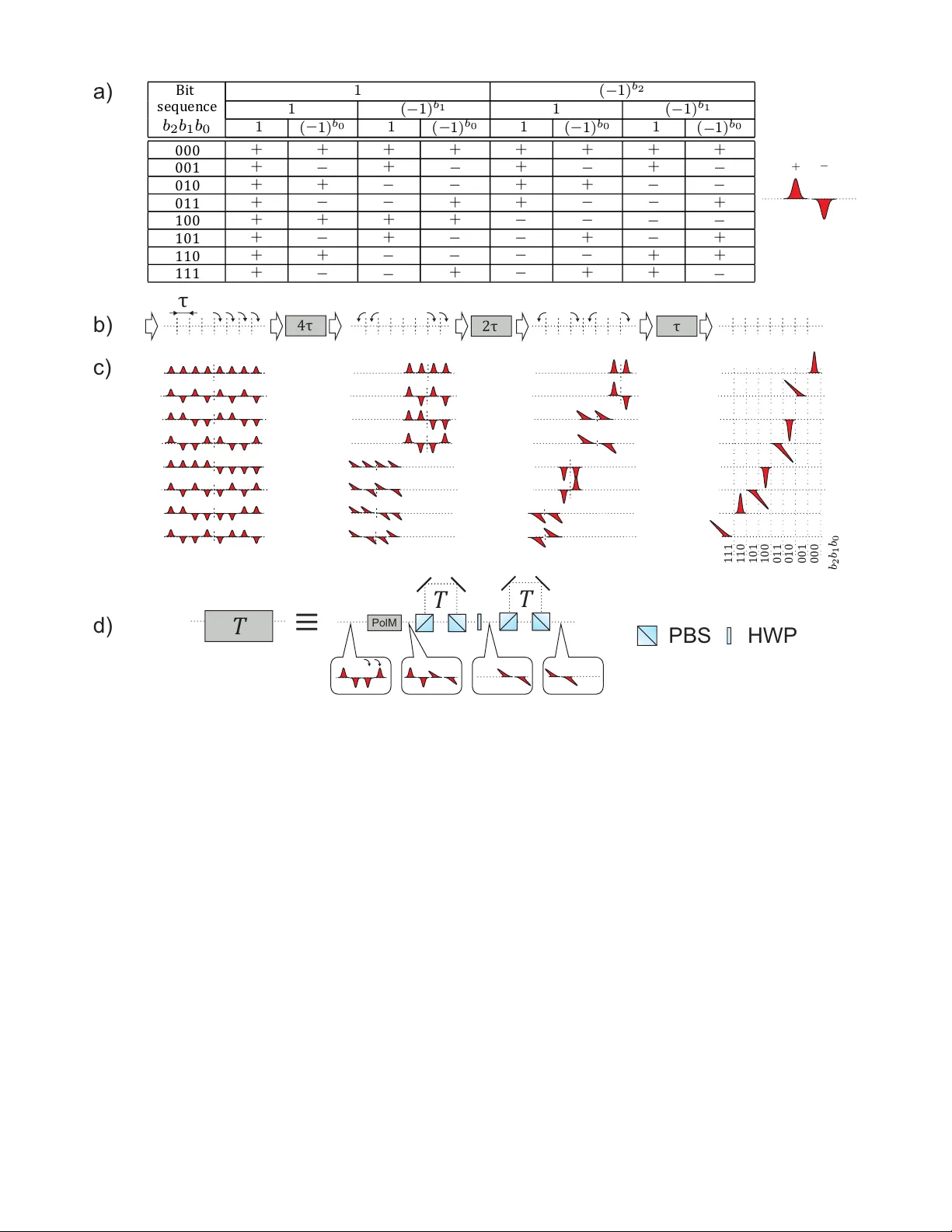
Structured Optical Recei v ers for Ef ficient Deep-Space Communication K onrad Banaszek and Michał Jachura Centre of New T echnologies Univ ersity of W arsaw PL-02-097 W arszaw a, Poland E-mail: k.banaszek@cent.uw .edu.pl Abstract —W e discuss conceptual designs for structured optical recei vers that can alleviate the requir ement for high peak-to- av erage po wer ratio in photon-starv ed optical communication. The basic idea is to transmit sequences of suitably modulated coherent light pulses whose energy can be concentrated in a single temporal bin on the receiver side through optical interference. T wo examples of scalable architectures for structured receivers are presented. The first one, based on active polarization switch- ing, maps Hadamard codewords composed fr om the binary phase shift keying (BPSK) constellation onto the standard pulse position modulation (PPM) format. The second r eceiver , using solely passive optical elements, conv erts phase-polarization patterns of coherent light pulses into a single pulse preser ving a synchronized time of arrival. Such a conv ersion enables implementation of a communication protocol equivalent to the PPM scheme but with distributed optical po wer provided that the intersymbol guard- time exceeds the pattern length. I . I N T RO D U C T I O N The pulse position modulation (PPM) format, routinely used in space optical communication, requires an unbalanced dis- tribution of instantaneous light intensity [1], [2]. This results in stringent demands on the peak-to-average power of laser light source used in the transmitter . A common design for the transmitter relies on carving the PPM signal out of a continuous wave laser beam using an electro-optic amplitude modulator and subsequently amplifying it with the help of e.g. an erbium-doped fiber amplifier . This architecture, known as the master -oscillator po wer amplifier (MOP A) [3], offers multigigahertz bandwidth limited by the speed of electro- optic modulators and photodetectors. The peak power of sev eral w atts offered by the MOP A architecture is sufficient for relati vely short communication links such as Earth-LEO, Earth-GEO or Earth-Moon [4], [5]. In deep-space communication scenarios optical peak power in the kilo watt range is indispensable and Q-switched laser transmitters are regularly used [6]. Although the y are able to deliver the desired peak power , the pulse repetition rate attainable in the Q-switching technique is limited to approx. 200 kHz, which compared to several GHz provided by MOP A significantly reduces practical transmission rates. Due to sev- eral detrimental factors such as the non-unit transfer efficienc y of pump power into the active medium and the limited optical- to-optical con version efficienc y of the acti ve medium, the wall-plug ef ficiency of Q-switched laser transmitters does not usually exceed 15% and is in general much lo wer than that attainable in the MOP A design. Furthermore, peak power lev els can exceed the damage threshold of optical components in the transmitter setup and may lead to heat dissipation issues. The requirements on the transmitter laser source can be significantly altered through the use of recently proposed structured optical recei vers. The basic idea is to spread the signal optical energy over multiple bins and to perform joint detection on sequences of incoming elementary symbols [7]. The adv antage offered by this strategy is known in quantum information science as the superadditivity of accessible infor - mation. A class of joint-detection schemes proposed by Guha [8] uses the well-known binary phase shift keying (BPSK) constellation to construct so-called Hadamard codewords. On the receiv er side, such codewords can be con verted using a linear optical circuit into the standard PPM format suitable for direct detection. Consequently , the spectral efficienc y of the PPM scheme [9], [10] can in principle be attained with uniform distribution of the signal optical po wer and phase modulation only in the transmitter setup. In this paper , we describe a conceptual design for a scalable receiver architec- ture that realizes conv ersion from Hadamard codewords into the PPM format using acti ve polarization switching. W e also present a second type of a structured optical receiv er , based on passiv e optical elements, that concentrates the entire optical energy of a phase-polarization pattern of incoming light pulses in a single time bin. W ith a sufficiently long intersymbol guard-time, such a receiver offers the performance of the PPM scheme with optical ener gy distributed ov er multiple time bins. I I . A C T I V E R E C E I V E R F O R H A DA M A R D S E Q U E N C E S The superadditiv e communication scheme proposed in [8] uses codew ords composed from the BPSK constellation whose two elements will be denoted symbolically as + and − . The codewords are chosen as rows of a Hadamard matrix. Hadamard matrices are orthogonal symmetric matrices with entries ± 1 that exist for dimensions equal to integer po wers of 2 and specific other natural numbers. For a Hadamard matrix of dimension 2 m , each ro w can be identified bijecti vely with a bit string b m − 1 . . . b 1 b 0 of length m , as illustrated with Fig. 1(a) for m = 3 . The bits define a hierarchy of ± sign relations between binary sections within a ro w . An individual entry in a ro w is giv en by a product of all ± 1 factors above it as shown in Fig. 1(a). PolM T T ≡ HWP PBS 4 τ 2 τ τ 111 110 101 100 011 010 001 000 T a) b) c) Bit 1 ( 1) b 2 sequence 1 ( 1) b 1 1 ( 1) b 1 b 2 b 1 b 0 1 ( 1) b 0 1 ( 1) b 0 1 ( 1) b 0 1 ( 1) b 0 000 + - + + + + + + 001 + + + + 010 + + + + 011 + + + + 100 + + + + 101 + + + + 110 + + + + 111 + + + + + - - - - - - - - - - - - - - - - - - - - - - - - - - - - - - - - - - b 2 b 1 b 0 + - τ d) Fig. 1. Activ e optical receiv er conv erting Hadamard codewords of length 2 m composed from the ± BPSK constellation into the 2 m -ary PPM format, shown for m = 3 . (a) Construction of Hadamard code words through a hierarchy of sign relations. Each entry is a product of ± 1 factors abo ve it. (b) Scalable architecture for a structured receiver consisting of active modules using delays 2 m − 1 τ , . . . , 2 τ , τ , where τ is the time bin separation. Curv ed arro ws indicate polarization switching implemented by the polarization modulator in each module. (c) Transformation of individual Hadamard codewords at the consecutiv e stages of the receiv er . (d) Setup of an individual module for a delay T . PolM, polarization modulator; PBS, polarizing beam splitter; HWP , half-wav e plate. The callouts illustrate the transformation of an exemplary Hadamard sequence + − − + for T = 2 τ . The chosen code word is used to modulate a sequence of 2 m coherent light pulses. On the receiver side, the pulses are inter- fered using a linear optical circuit such that for each code word the entire optical energy is concentrated in a different output port of the circuit. In the e xemplary implementation presented in the original proposal [8], pulses are fed into distinct spatial input ports of the circuit. If the received signal has the form of a pulse sequence arriving along one spatial path in consecutive time bins, using such a circuit would require prior rerouting and delaying indi vidual pulses. Alternativ ely , the linear optical transformation could be in principle realized in a multimode quantum memory system [11], but this technology is still in its infancy . A scalable architecture based on active polarization switch- ing that maps temporal Hadamard codewords directly onto the PPM format is presented in Fig. 1(b) for m = 3 . The architecture consists of a series of modules represented by rect- angular boxes. Fig. 1(c) sho ws the transformation of individual Hadamard codew ords by the modules. The internal setup of one module is depicted in Fig. 1(d). The first element of the module is a polarization modulator PolM which switches portions of the input signal between horizontal and vertical polarizations according to curved arrows sho wn in Fig. 1(b) before each module. The switching pattern is independent of the input codew ord. Next, the horizontal component of the signal is delayed with respect to the vertical one by time T specified for each module. This step can be realized using two polarizing beam splitters PBS and a delay line. As a result, horizontal and vertical components of the signal overlap in the same time bins. Because of fixed phase relations between these HWP PBS T ≡ T 4 τ 2 τ τ guard-time guard-time symbol symbol symbol a) b) 8 τ Fig. 2. Passi ve optical receiv er producing single pulses from phase-polarization patterns. (a) The scalable architecture for patterns spanning 2 m bins shown for m = 4 . Each module represented by a square box and labelled with a delay T consists of a polarization-selectiv e delay line follo wed by a half-wav e plate. (b) The phase-polarization pattern for m = 3 used in a 16-ary PPM format. The peak power requirement is reduced eightfold. components which follow from the hierarchical construction of Hadamard code words presented in Fig. 1(a), the signal in each bin will hav e one of two diagonal polarizations oriented at +45 ◦ or − 45 ◦ . The diagonal polarizations are brought to the rectilinear basis of the horizontal and the vertical polarizations with the help of a half-wave plate HWP . In the last step, the horizontal polarization is delayed with respect to the vertical one in another delay line introducing delay T for the horizontal polarization. This reduces the length of the sequence by a factor of two and doubles the intensity of each output light pulse. For Hadamard sequences of length 2 m and the temporal spacing between consecutive bins equal to τ , the delay of the the first module is 2 m − 1 τ . The delay of each subsequent module is halved until the single-bin delay τ is reached. Thus m modules are needed altogether , which makes the architecture scaling logarithmically in the codeword length. It is easy to see that at the output of the last module the energy of the entire Hadamard sequence is concentrated in a single time bin whose position is gi ven by the sum P m − 1 k =0 b k 2 k , i.e. the natural number specified in the binary representation by the bit sequence b m − 1 . . . b 1 b 0 . Thus Hadamard codewords are con verted into the PPM symbols that can be identified using di- rect detection from the timing of photocount e vents. Instances when no detection ev ent is recorded over the entire Hadamard sequence are interpreted as erasures in a full analogy with the standard PPM communication scheme. Note that one can also devise a tree-like architecture built from modules that comprise a polarization modulator and a single delay stage. At the output of each module the two diagonal polarizations are separated, rotated to the vertical polarization, and fed into a pair of modules with half the delay . Such an architecture con verts Hadamard sequences into the spatial PPM format, but it would require 2 m − 1 modules with activ e polarization switching. I I I . P A S S I V E R E C E I V E R F O R P H A S E - P O L A R I Z A T I O N PA T T E R N S An altenati ve option to reduce the requirement for the high peak-to-av erage power ratio on the transmitter side is to generate phase-polarization pulse patterns that span multiple time bins. W e will demonstrate that with a suitable choice of phase and polarization relations between indi vidual pulses in a pattern, such patterns can be conv erted using a structured receiv er build only from passiv e optical elements into one pulse occupying a single time bin. The above idea is sho wn in Fig. 2(a) for a pattern spanning 2 m bins with m = 4 . The conv ersion takes place in a sequence of modules characterized by delays 2 m − 1 τ , . . . , 2 τ , τ , where τ is the time bin spacing. First, each module delays the horizontally polarized components of the signal with respect to the vertical ones in order to attain a two-fold contraction of the pattern length. The coherently superposed components, emerging from the delay stage at ± 45 ◦ polarizations, are rotated by a half-wa ve plate to the rectilinear basis before entering the next stage. After all m stages, the sequence of modules produces a pulse in a single time bin that carries the optical energy of the entire pattern. Its temporal location can be detected by photon counting. Information is encoded in symbols with dif ferent pattern arriv al times analogously to the standard PPM format as shown in Fig. 2(b) for m = 3 and the PPM order equal to 16 . In order to av oid an overlap between patterns, the guard-time between consecutive symbols needs to be longer than the pattern length. An elementary way to determine polarizations and phases of individual pulses in the pattern is to analyze the action of the presented circuit in rev erse, when the output port is hypothetically injected with a single pulse. Note that this rev erse mode has been pre viously used for time-multiplexed photon number resolv ed detection using Geiger -mode operated av alanche photodiodes, with horizontal and vertical polar- izations corresponding to a pair of distinct optical paths in single-mode fibers [12], [13]. The pattern can be generated from a laser beam polarized at 45 ◦ using two crossed phase modulators modulating respectively the horizontal and the vertical components. The beam needs to be blocked outside the timespan of the pattern. If the symbol frame is of the same duration as the intersymbol guard-time, this results in the effecti ve 50% usage of the optical po wer . Including a second pattern corresponding to the orthogonal polarization at the cir- cuit output doubles the number of a v ailable PPM symbols. In order to allo w rotational freedom between the transmitter and the receiv er , polarizations labelled as horizontal and vertical should be conv erted for transmission into circular ones using a quarter wa ve plate. I V . D I S C U S S I O N The demand for high peak-to-av erage power on the trans- mitter side in photon-starved optical communication can be in principle alleviated through the use of structured optical receiv ers. In this approach, the transmitter emits sequences of mutually coherent light pulses modulated in phase and optionally also in polarization. The recei ver combines pulses using optical interference to concentrate the ener gy of the entire sequence into a single time bin. The information is encoded in the position of the produced single pulse, which provides efficienc y comparable to that of the standard PPM format. While the complication of the transmitter setup can be viewed as relati vely minor , the construction and the operation of a structured optical receiv er poses a number of technical challenges. The receiv er needs to accommodate spatial and temporal mode distortions that may occur in the course of propagation through the optical channel, hence its construc- tion should hav e inherent multimode capability . Significant progress has been made tow ards tolerance of distortions in interferometric recei vers in the context of free-space quantum key distribution [14]. All delays need to be stabilized to a fraction of the wav elength to ensure correspondingly con- structiv e or destructive interference in individual time bins. In order to ensure high visibility of the optical interference, distortions introduced by the optical channel need to fluctuate ov er a time scale that exceeds substantially the duration of entire code words or phase-polarization patterns. Also, one can expect that optical interference will be perturbed at the edges of individual time bins due to the finite switching time of electro-optic modulators employed in the transmitter and the receiv er . A possible solution w ould be to use as the light source a pulsed laser with the repetition rate corresponding to the time bin separation. This would concentrate the optical power at the center of the bins, where modulators are in a settled state. A C K N O W L E D G M E N T The authors w ould like to thank F . E. Becerra, C. Marquardt, M. Shaw , and W . W asile wski for insightful discussions. This work is part of the project “Quantum Optical Communication Systems” carried out within the TEAM programme of the Foundation for Polish Science co-financed by the European Union under the European Regional De velopment Fund. R E F E R E N C E S [1] A. W aseda, M. Sasaki, M. T akeoka, M. Fujiwara, M. T oyoshima and A. Assalini, “Numerical evaluation of PPM for deep-space links, ” J. Opt. Commun. Netw ., vol. 3, pp. 514-521, May 2011. [2] B. Moision and W . F arr , “Range Dependence of the Optical Communi- cations Channel, ” IPN Prog. Rep., pp. 42-199, November 2014. [3] D. O. Caplan, “Laser communication transmitter and receiv er design, ” J. Opt. Fib. Commun. Rep., vol. 4, pp. 225-362, September 2007. [4] S. Constantine, L. E. Elgin, M. L. Stev ens, J. A. Greco, K. Aquino, D. D. Alves, and B. S. Robinson, “Design of a high-speed space modem for the lunar laser communications demonstration, ” Proc. SPIE 7923, Free- Space Laser Communication T echnologies XXIII, pp. 792308-1–792308- 9, February 2011. [5] M. T oyoshima, T . Fuse, D. R. Kole v , H. T akenaka, Y . Munemasa, N. Iwakiri, K. Suzuki, Y . Ko yama, T . Kubooka, M. Akoika, and H. Kunimori, “Current status of research and dev elopment on space laser communications technologies and future plans in NICT , ” 2015 IEEE International Conference on Space Optical Systems and Applications (ICSOS), New Orleans, LA, pp. 1-5, October 2015. [6] H. Hemmati, Deep-Space Optical Communication, Chapter 5: Flight T ransceiv er , Wiley , October 2005 [7] S. Guha, Z. Dutton, and J. H. Shapiro, “On Quantum Limit of Optical Communications: Concatenated Codes and Joint-Detection Receivers, ” IEEE Int. Symp. Inf. Theor . Proc., pp. 274278, August 2011. [8] S. Guha, “Structured Optical Receivers to Attain Superadditiv e Capacity and the Holev o Limit, ” Phys. Rev . Lett., vol. 106, pp. 240502-1–240502- 4, June 2011. [9] L. W ang, and G. W . W ornell, “ A refined analysis of the Poisson channel in the high-photon-efficiency regime, ” T rans. Inf. Theory , vol. 60, pp. 4299-4211, April 2014. [10] M. Jarzyna, P . Kuszaj, and K. Banaszek, “Incoherent on-off keying with classical and non-classical light”, Opt. Express, v ol. 23, pp. 3170-3175, February 2015. [11] A. Klimek, M. Jachura, W . W asilewski, and K. Banaszek, “Quantum memory receiv er for superadditiv e communication using binary coherent states, ” J. of Mod. Opt., vol. 63, pp. 2074-2080, April 2016. [12] D. Achilles, C. Silberhorn, C. ´ Sliwa , K. Banaszek, and I. A. W almsley , “Fiber-assisted detection with photon number resolution, ” Opt. Lett., vol. 28, pp. 2387-2389, December 2003. [13] M. J. Fitch, B. C. Jacobs, T . B. Pittman, and J. D. Franson, “Photon- number resolution using time-multiplexed single-photon detectors, ” Phys. Rev . A, vol. 68, pp. 043814-1–043814-6, October 2003. [14] J. Jin, S. Agne, J.-P . Bourgoin, Y . Zhang, N. L. L ¨ utkenhaus, “Efficient time-bin qubit analyzer compatible with multimode optical channels, ” arXiv:1509.07490, September 2015.
Original Paper
Loading high-quality paper...
Comments & Academic Discussion
Loading comments...
Leave a Comment