Finite Large Antenna Arrays for Massive MIMO: Characterization and System Impact
Massive MIMO is considered a key technology for 5G. Various studies analyze the impact of the number of antennas, relying on channel properties only and assuming uniform antenna gains in very large arrays. In this paper, we investigate the impact of mutual coupling and edge effects on the gain pattern variation in the array. Our analysis focuses on the comparison of patch antennas versus dipoles, representative for the antennas typically used in massive MIMO experiments today. Through simulations and measurements, we show that the finite patch array has a lower gain pattern variation compared with a dipole array. The impact of a large gain pattern variation on the massive MIMO system is that not all antennas contribute equally for all users, and the effective number of antennas seen for a single user is reduced. We show that the effect of this at system level is a decreased rate for all users for the zero-forcing MIMO detector, up to 20% for the patch array and 35% for the dipole array. The maximum ratio combining on the other hand, introduces user unfairness.
💡 Research Summary
Massive MIMO is a cornerstone of 5G, promising unprecedented spectral efficiency by employing hundreds of antenna elements at the base‑station. Most analytical works, however, treat each antenna as an ideal isotropic radiator with identical gain, focusing only on the statistical properties of the propagation channel. In practice, when a large number of radiating elements are placed in close proximity, mutual coupling and edge effects cause the individual element gain patterns to deviate significantly from the ideal. This paper investigates how those deviations affect system‑level performance, comparing two antenna types that dominate current massive‑MIMO testbeds: printed patch antennas and simple half‑wave dipoles.
Methodology
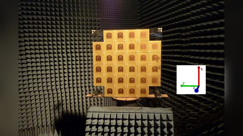
A planar 8 × 8 array (64 elements) operating around 3 GHz is modeled with a full‑wave electromagnetic solver (CST Microwave Studio). Both the S‑parameters (to capture coupling) and the far‑field radiation patterns of each element are extracted. The same geometry is fabricated for experimental verification; element‑wise gain is measured in an anechoic chamber. To translate the physical gain variation into a communication‑system model, the authors introduce a diagonal gain matrix G and define a modified channel Ĥ = G · H, where H is the conventional i.i.d. Rayleigh channel.
Pattern Variation Results
The standard deviation of the element gain (σ_gain) across the array is used as a metric of pattern uniformity. For the patch array σ_gain ≈ 1.2 dB, while for the dipole array σ_gain ≈ 2.8 dB. The larger spread in the dipole case is attributed to stronger mutual coupling (the dipoles are electrically longer and less shielded) and more pronounced edge loss; the patch elements benefit from a ground plane and a more confined current distribution, which suppresses coupling.
Impact on Linear Detectors
The authors evaluate two classic linear receivers: Zero‑Forcing (ZF) and Maximum Ratio Combining (MRC). For ZF, the effective number of antennas that actually contribute to a given user can be expressed as
\
Comments & Academic Discussion
Loading comments...
Leave a Comment