Prototyping with SDR: a quick way to play with next-gen communications systems
In this paper we present our approach regarding the implementation of new wireless radio receiver exploiting filterbank techniques, using a software-development driven approach. Since most of the common radio communications systems share a similar st…
Authors: Jorge Bar, a, Pol Henarejos
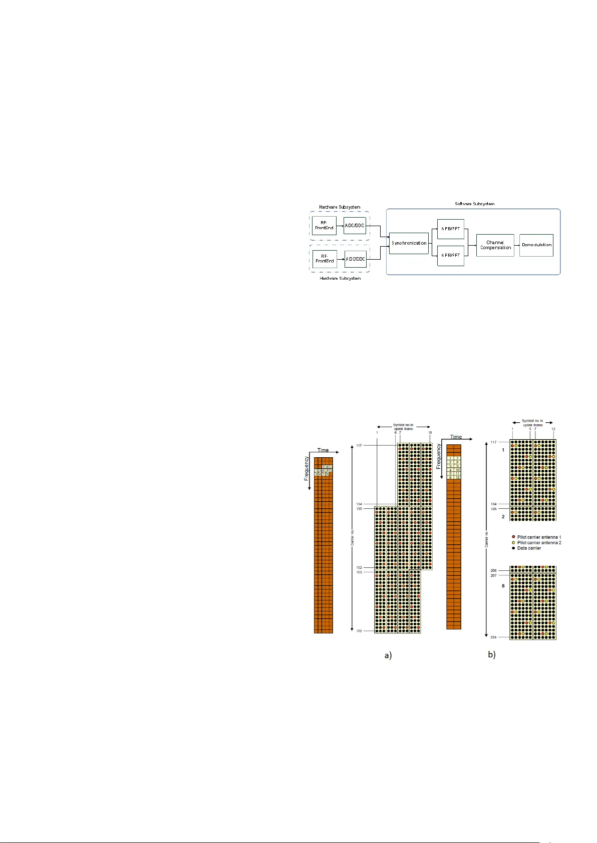
Prototyping with SDR: a quick way to play with ne xt-gen communications systems Jorge Baranda ∗ , Pol Henarejos ∗ , Y an Grunenberger ∗ and Montse N ´ ajar ∗ † ∗ Centre T ecnologic de T elecomunicacions de Catalunya (CTTC), Castelldefels,Barcelona (Spain) † Dep. of Signal Theory and Communications, Universitat Polit ` ecnica de Catalunya (UPC) Email: { jorge.baranda, pol.henarejos, yan.grunenberger } @cttc.es , montse.najar@.upc.edu Abstract —In this paper we present our approach regarding the implementation of new wireless radio r eceiver exploiting filterbank techniques, using a software-dev elopment driven ap- proach. Since most of the common radio communications systems share a similar structure, this can be exploited creating a framework which provides a generic layout and tools to construct a reconfigurable transmitter and/or recei ver . By combining the use of the Uni versal Softwar e Radio Peripheral version 2 (USRP2) with a generic object-oriented framework of our own b uilt on top of the GNU Radio software framework, we hav e been able to quickly implement a working proof of concept of an Uplink (UL) Filterbank Multicarrier (FBMC) recei ver , both for Single- Input Single-Output (SISO) and Multiple-Input Multiple-Output (MIMO) scenario, within the project of the 7th European frame- work called PHYD Y AS. W e described her e the methodology we hav e applied from software engineering in order to build this demonstrator , which shows the suitability of using Software Defined Radio (SDR) technologies f or fast prototyping of new wireless communication systems. I . I N T R O D U C T I O N In the past, real-world prototyping of communication sys- tems were not very common due to high financial costs and long development times deriv ed from the use of dedi- cated hardware (HW) such as field programmable gate arrays (FPGA), application specific integrated circuits (ASICs) and digital signal processors (DSPs). Nonetheless, this implemen- tation is vital because they allo w the exposure of problems, such as unexpected system beha vior , real-world impairments and design flaws. In spite of this, HW based approach also suffers from lack of flexibility and modularity , which on the other hand are highly desirable qualities. These qualities are pro vided by SDR platforms, where physical layer (PHY) and medium access control (MA C) functions are performed in software in a General Purpose Processor (GPP), while only the radio frequency (RF) and signal conv ersion functions such as sampling and downcon version are performed in programmable hardware. Moreo ver , these platforms use, as dev elopment tools, popular high level programming languages such as C/C++, which present the following advantage: as these programming languages are dominant, there is a great number of experienced programmers and a number of well- written peer -revie wed libraries are available, which open the door to create communities of software radio de velopers. Until no w , SDR implementations aimed to replicate already HW -implemented signal processing schemes into the software domain. But in recent years, the ev olution of SDR technolo- gies is making them a real alternative at the time to build flexible testbeds implementing communication systems with high demands on bandwidth to accommodate high data rate transmission, both for current and next generation of wireless systems such as Mobile W iMAX, 3GPP Long T erm Evolution (L TE), IEEE 802.11n and the upcoming White Space De vices, were nov el algorithms can be ev aluated, accelerating the transition from simulation to demonstration with real radio signals. This ev olution has been possible thanks to increased capacity platform interfaces, increasingly di verse range of processors, increased on-board processing capability and improvement in the quality of RF components such as mixers and data con verters. In [1], a list of different SDR platforms can be found. From all of them, the authors want to highlight the family of platforms developed by Ettus Research [2], specially the USRP2 and its predecessors, because of its trade-off between price and performance. Furthermore, these are the hardware platforms for the GNU Radio project [3]. GNU Radio project is an enormous body of pre-written, free software in continuous de velopment by a community of programmers, who hav e dev eloped blocks of code in C++ to handle a wide range of signal processing functions, as well as the blocks which interface between the USRP de vices and the GPP . A. Related work Not so many papers describing SDR implementation are written from the architectural point of view , most of them either describe the technical means (FPGA, DSP) or explain in detail a specific implementation, but only a few describe the work flow process and its viability . As introduced by Mitola in the preface of [5], ”Knowing how to code a radio algorithm in C on a DSP just does not giv e a software engineer the core skills needed to contribute effecti vely to software radio architecture”. While this is entirely true, we can also state that the same could be applied to radio engineers when it comes to software de velopment. In [6], lots of the actual tools used rely on proprietary elements, which definitely reduce the possibility to simple reuse of part of the ef fort already done. This is partly due to use of hardware-specific accelerator , and partly due to the strict framework imposed by the a vaibility of Simulink-based generator tools. In [7] there is an interesting feedback on how software engineering practices hav e eased the implementation process, but specifically adapt the platform to the Global Positioning System (GPS) designer point of view . B. P aper contribution Regarding all the positiv e aspects and the future possibilities of SDR technologies, this article aims to introduce a flexible dev elopment framew ork for rapid prototyping and algorithm verification of physical layer concepts named uPHYLA (Uni- versal Physical Layer) based on the family of USRP devices and the GNU Radio softw are project. Using the philosophy of GNU Radio project, uPHYLA framework has been concei ved and developed to make shorter the learning curve of GNU Radio, so researchers can use it with a basic understanding on the GNU Radio project. Mainly , this is achiev ed with the only use of a high level programming language (C++) instead of the intensiv e use GNU Radio makes of the Python scripting language. The fact that all signal processing blocks are designed as entities of the same type makes easier its integration in dif ferent radio communications systems. Furthermore, the designed architecture of uPHYLA aims for the following aspects: efficienc y , modularity , leg acy , reusabil- ity and fle xibility . In order to achie ve these desired properties, best-practices techniques of software engineering have been taken as a reference. These techniques are going to be de- scribed in following sections. uPHYLA frame work has been pro ved as an effecti ve tool when dev eloping the proof of concept of the receiv er of the UL FBMC system (both for SISO and MIMO 2x2 scenario) which includes the novelties presented within the project of the 7th European framework called PHYD Y AS [4]. I I . U P H Y L A F R A M E W O R K D E S C R I P T I O N uPHYLA is intended to be a tool to implement into software the PHY Layer of any communication system to demonstrate, using a short dev elopment time, the performance of the different algorithms included in the software chain with real digitized signal. Hence, the design is oriented to create a layout where different communications subsystem can lay there. In this sense, uPHYLA is conceived as an upper architecture wrapping dif ferent libraries and modules to reproduce a radio communication system. The herein proposed architecture contains a core that can construct each system with the set of subsystems in volv ed in the communication process, which are fed with the samples coming from any de vice of the USRP family . Each subsystem is constituted as the connection of self-programmed basic blocks or the ones present in GNU Radio. uPHYLA uses the GNU Radio scheduler to distribute the samples among the in volv ed blocks, so the software developer has not to be worried about the sampling flow of the whole process, remaining only as a task the design of the subsystems where Fig. 1. Unified Modeling Language (UML) diagram of uPHYLA wrapper classes samples are processed. Unlike GNU Radio, in the uPHYLA framew ork all is done in C++, avoiding the use of Python. Not only the algorithm of the processing block is coded in C++ but also its definition in the system layout and the intercon- nections with other blocks. In this way , uPHYLA enhances the performance of GNU Radio in terms of execution time because compiled languages (C++) run faster than interpreted languages (Python). The core of the uPHYLA framework platform resides in the wrapper files. W ith these files, the platform is organized into two-le vel architecture to make more flexible the creation and insertion of ne w modules and to make transparent the use of the different processing blocks of the GNU Radio framework. Wrapper files hav e been de veloped dividing the system into two types of classes. The upper lev el interacts with its coun- terpart ”gr class” , making possible the use of the GNU Radio resources, as it is illustrated in the Fig. 1. In the bottom lev el, the different basic processing blocks (self-programmed or the ones included in the GNU Radio frame work) are connected to constitute a stage in the processing chain, for instance the synchronization stage of a receiv er . There is one main class, called ‘Implementor’ which acts as the container and the link of the two parts of the system and implements the layout of the communication system. Other important libraries used in the uPHYLA framework are Boost([8]) and QT/qwt([9],[10]). In GNU Radio, Boost libraries are used mostly for an ef ficient memory management. In the uPHYLA framework is used as well to provide the com- munication system of an interface to be configured by file or by command line, so it is not necessary to recompile when an option has been modified, for instance the decimation rate ap- plied in the USRP device. Graphical interface capabilities are provided by QT/qwt libraries. These capabilities are included in the architecture in such way they can be particularized to show rele vant information of each communication system. I I I . P R O G R A M M I N G M E T H O D O L O G Y After a brief description of the dev eloped frame work, this Section aims to explain the dif ferent software engineering techniques used to provide the framework of the capacities before mentioned. The systematic application of these kind of techniques speeds up the dev elopment process, reduce the time to solve some problems with ef fectiv e prov en solutions and ensures traceability , which reduces maintenance costs. A. Design P atterns The idea of design patterns was introduced by Christopher Alexander in 1977 as an architectural concept. The application into the software world was pushed by [11]. Software design patterns provide solutions to a common occurring problem in software design, facilitating the reuse of successful proven designs. As a side characteristic, the use of them helps to create a common terminology which simplifies communication between the members of the de velopment team. As the nature of the problem they attempt to solve is dif ferent, they are subdi vided into categories: creational (patterns dealing with object creation or class instantiation), structural (patterns which define relationships between elements to obtain new functionalities) or behavioral (patterns which are concerned with the communication between objects). The ef fectiv eness of design patterns make them indispensable at the time to de velop serious software projects. In fact, GNU Radio framew ork incorporates many of them. This is the reason why it seems natural to adopt them in the conception of our frame work. Reg arding this, the implementation of the pre- sented frame work applies structural (Decorator and Adapter) and behavioral patterns (Strategy and T emplate Method). B. Softwar e development methodology When attempting to create efficient and high quality soft- ware, the authors think that it is very important to follow the methodology imposed by the Software De velopment Life Cycle (SDLC) [12]. No one can discuss that developing software is a creativ e process, but this has to be systematized in order to not waste this creativity ener gy . The analysis of the problem, the identification and a detailed description of the requirements , the definition of the architectur e and the creation of an exhausti ve testing plan are totally necessary before the implementation . Special attention have to be paid to the execution of the testing plan because it validates the fulfillment of the defined requirements. Follo wing a test-driv en approach [13], the authors defined different lev els of testing which serve to validate not only the performance of each of the communication systems which lays in the uPHYLA frame work but also the robustness of the uPHYLA architecture. These different levels are: • Unit testing: the aim of this test is to check if the minimum basic processing block performs its assigned functionality correctly . • Integration testing: the dif ferent basic processing blocks which constitute an entity are tested together to verify if the y meet the feature they are supposed to carry out. This process is repeated with an incremental aggregation of different entities. The previous le vels of testing imply only the software subsys- tem and hav e been implemented with the CppUnit frame work [14], which is used also in the GNU Radio Project. The use of this tool allo ws running the implemented tests in an automated way and the addition of new ones very easily . • System testing: at this level, the complete chain is tested, both the software and the hardware subsystems (a device of the USRP family). W ith these tests, it is ev aluated the de gree of compliance of the implementation with the specified requirements. I V . U P H Y L A B A S E D D E V E L O P M E N T : U L F B M C R E C E I V E R The uPHYLA framew ork accomodates the proof of con- cept of the UL FBMC receiv er (both for SISO and MIMO 2x2 scenario) proposed in the project of the 7th European framew ork called PHYD Y AS [4]. The aim of this project is to propose a physical layer for future radio systems based on FBMC. Although this technique presents higher computational complexity , it has better performance in terms of spectrum efficienc y than present OFDM based solutions and it is better suited to the new concepts of Dynamic Access Spectrum Management (DASM) and Cogniti ve Radio (CR). For this purpose, a W iMAX based simulator programmed in MA TLAB was dev eloped within the project. As being W iMAX based, the de veloped work within this project aims to be compared with state of the art systems in order to gain acceptance within the community . The proof of concept implemented under uPHYLA framework was based upon this simulator and the main characteristics are gathered in T able IV. T ABLE I S Y ST E M PA R AM E T E RS Parameter V alue Carrier Frequency 2.595 GHz Number of subcarriers 1024 Bandwidth 10 MHz Sampling Rate 10 MHz A. Har dwar e Configuration The host computer where all the baseband processing is performed is equipped with an Intel Core 2 Quad CPU Q9400 running at 3.2 GHz (overclocked) in combination with 4 GByte of av ailable DDR2 RAM, whose clock frequency is 800 MHz. The host is equipped with a dual-port Gigabit Ethernet (GbE) card (Intel 82576EB controller) connected to the PCI-E x8 slot of the motherboard. This card allows the connection of each of the USRP2s to one port of the card to form the MIMO receiv er , without needing the MIMO cable of the manufacturer [2], which allows to connect 2 USRP2s with a single port network card. The use of this dual-port card is justified because at the time the proof of concept was dev eloped, the software controlling the MIMO cable was not presenting a stable release. Each USRP2 is equipped with a RFX2400 daughter board which acts as a RF front-end for the range of frequencies comprised between 2.3 to 2.9 GHz. In order to form the MIMO receiver , USRP2s devices need to be synchronized. This synchronization is performed by means of an external 10 MHz reference clock provided by an arbitrary wav eform generator . This de vice is used also to generate a one pulse per second (1 PPS) signal, which acts as the trigger to synchronize the recei ved stream of samples from the USRP2 de vices. These references are connected directly at the front panel of the USRP2 devices through SMA connectors. As the proof of concept herein described only comprises the receiv er, extra hardware was needed to simulate the transmit- ter . In the case of the SISO scenario, baseband signal was generated with the simulator de veloped within the PHYD Y AS project. This signal was loaded into an Agilent E4438C V ector Signal Generator (ESG) to be modulated at 2.595 GHz. Then samples passed through the channel emulator (Elektrobit C8 [15]) connected to the USRP2 de vice. In the case of the MIMO 2x2 scenario, this basic setup presents some particularities. The simulator generates a stream of baseband samples for each antenna, so these samples are loaded into dif ferent ESGs, where one acts as a master and the other as slav e and are configured and adjusted to produce an aligned signal at the output of each device. Each output of the ESG is connected to different channels of the channel emulator and then connected to USRP2 devices. B. Softwar e Configuration The UL FBMC receiver demonstrator has been de veloped under the 64bit version of Ubuntu 10.04 and the GNU Radio framew ork version 3.2.2 [3]. GNU Radio mainly provides to the uPHYLA frame work of the scheduler which manages the data flow among signal processing blocks. The cited release was preferred in front of version 3.3.0 to av oid stability problems, because this version was just released when the demonstrator frame work was being dev eloped. The options interface created for this receiver allows the selection of the working mode (SISO or MIMO), the configuration of the filters and the specification of the configuration of the frame (number of symbols, number of subcarriers, number of data- slots). The graphical interface is designed with QT version 4 and qwt version 5.2.1. It displays the performance of the receiv er: magnitude of the channel estimation, demodulated constellation, cumulative Bit Error Rate (BER), Signal to Noise Ratio (SNR) and Carrier Frequency Offset v alue (CFO) (see Fig. 4). USRP2 de vices are configured by means of UHD (Uni versal Hardware Driv er), which aims to be the unique driv er for the USRP family of devices. The tests during the dev elopment were carried out with the versions released between 08/17/2010 and 11/24/2010. C. Demonstration The UL FBMC receiv er dev eloped under the uPHYLA framew ork integrates the algorithms dev eloped in the dif- ferent workpackages of the PHYD Y AS project included in [17],[18],[19],[20]. This receiver can be configured to work in SISO mode or in MIMO 2x2 mode using spatial multiplexing with Zero-Forcing (ZF) equalization. The implemented receiv- ing chain is presented in Fig. 2. Fig. 2. Structure of the UL FBMC MIMO 2x2 receiver The frame structure used in the proof of concept of the PHYD Y AS project is depicted in Fig. 3, including a detail of the data and the pilot carriers allocation. The uplink zone cov ers 15 OFDM symbols in the SISO scenario, and 12 OFDM symbols in the MIMO scenario. In both scenarios, the pilots are scattered through 12 slots of allocated data using Adaptiv e Modulation Coding (AMC) as the pilot permutation scheme. Fig. 3. UL FBMC receiv er frame Structure. a) represents the SISO scenario and b) represents the MIMO 2x2 scenario. It is important to remark that the frame is completed with a preamble, which is not sho wn here. This preamble is needed because the implementation only covers the uplink recei ver . Fig. 4. Performance of the UL FBMC MIMO 2x2 receiver Normally , this preamble should not be needed because the synchronization to the base station is performed during the connection setup by means of a two-way process. After the signal is synchronized, the Analysis FilterBank operation is performed into the receiv ed signal to undo the Synthesis Filterbank operation applied in transmission (both operations are the ke y components of the PHYD Y AS project). Then the signal passes to the channel compensation module. In this module, the channel estimation process has to take into account the transmultiplex er response of the applied bank of filters [18]. The channel estimation is obtained by means of a two-dimensional linear interpolation based on the channel behavior at the pilot positions. Finally , the equalization is performed using the ZF criterion. The applied channels are ITU-R channel V ehicular A (VEHA) or Pedestrian B (PEDB), both presented in [21]. At the demodulation stage, the signal is postprocessed to undo the Offset QAM (OQAM) modulation inserted in the FBMC architecture and the modulated trans- mitted symbols are obtained. Fig. 4 depicts the performance of the recei ver when demodulating QPSK symbols and a VEHA channel is applied. V . C O N C L U S I O N S In this paper , the uPHYLA software framework to develop communication systems is presented. The use of software engineering techniques in the conception, implementation and maintenance of uPHYLA provides the framework with desirable qualities such as flexibility and modularity . This framew ork makes more straightforward to researchers the testing of new algorithms, accelerating the transition from simulation to practical demonstration with real signal and with the simplicity of using a common programming language such as C++. uPHYLA frame work has been proven effecti ve in the dev elopment of an UL FBMC receiv er with MIMO capabilities, which includes present nov elties in the field of multicarrier communications. This demonstration together with the hardware evolution in next years shows that SDR technologies are a real alternativ e to build flexible testbeds implementing communication systems with high demands on bandwidth to accommodate high data rate transmission. A C K N O W L E D G M E N T S The authors would like to thank Francisco Rubio, Antonio Pascual Iserte and Miquel Payar ´ o for his wise recommenda- tions, help and advice in technical issues related to under- standing of multicarrier communication systems and hardware configuration. This work has been supported by the European Comission in the frame work of the FP7 project PHYD Y AS (contract number INFSO-ICT -211887). R E F E R E N C E S [1] R. Farrell, M. Sanchez, and G. Corley , “Software-Defined Radio Demon- strators: An Example and Future T rends”, International Journal of Digital Multimedia Br oadcasting , vol. 2009, Article ID 547650, 12 pages, 2009, doi:10.1155/2009/547650. [2] Univ ersal Software Radio Platform, Ettus Research LLC, http://www .ettus.com [3] “GNU Radio, the GNU Software Radio project, http://gnuradio.or g/redmine/wiki/gnuradio [4] Physical Layer for Dynamic Spectrum Access and Cognitive Radio, http://www .ict-phydyas.org/ [5] J. Mitola, “Software Radio Architecture: Object-Oriented Approaches to W ireless Systems Engineering, ” W iley , 2002. [6] C. Mehlfuhrer , M. Rupp, F . Kaltenberger , G. Humer , “ A scalable rapid prototyping system form Real-T ime MIMO OFDM T ransmissions, ” The 2nd IEE/EURASIP Conference on DSP enabledRadio , 19-20 Sept. 2005. [7] C. Fernandez-Prades, C. A viles, L. Este ve, J. Arribas, and P . Closas, “Design Patterns for GNSS Software Receivers, ” NA VITEC, 5th ESA W orkshop, 8-10 Dec. 2010. [8] Boost Homepage, http://www .boost.or g/ , Retriev ed: June 10, 2011. [9] QT Homepage, http://qt.nokia.com/products/ , Retrieved: June 10, 2011. [10] Qwt Project Page, http://qwt.sourcefor ge.net/ , Retrieved: June 10, 2011. [11] E. Gamma, R.Helm, R.Johnson and J.Vlissides,“Design Patterns Ele- ments of Reusable Object-Oriented Software”, Addison W esley , Upper Saddle Ri ver , NJ, 1995. [12] E.J. Braude,“Software Engineering: An Object-Oriented Perspecti ve”, John W iley and & Sons, NY , 2001. [13] D. Janzen and H.Saiedian, “T est-driv en development concepts, taxon- omy and future direction, ” Computer , v ol. 38, no. 9, pp. 43-50, Sept. 2005. [14] CppUnit Project Page, http://sourcefor ge.net/pr ojects/cppunit/ , Re- triev ed: June 10, 2011. [15] PR OPSim, C8 wideband multichannel simulator, www .propsim.net. [16] UHD Project P age, http://www .ettus.com/uhd docs/manual/html/index.html , Retriev ed: June 10, 2011. [17] ICT PHYD Y AS, “D2.1 - Data-aided synchronization and initialization (single antenna). ” [18] ICT PHYD Y AS, “D3.1 - Equalization and demodulation in the receiver (single antenna). ” [19] ICT PHYD Y AS “D4.2 - MIMO T echniques and Beamforming. ” [20] ICT PHYD Y AS “D5.1 - Prototype filter and structure optimization. ” [21] ICT PHYD A YS “D9.1a - WiMAX FBMC-OFDM comparison scenar - ios. ”
Original Paper
Loading high-quality paper...
Comments & Academic Discussion
Loading comments...
Leave a Comment