Kramers Kronig PAM transceiver and two-sided polarization-multiplexed Kramers Kronig transceiver
We propose two transceiver schemes based on Kramers Kronig (KK) detection. One targets low-cost high-throughput applications and uses PAM transmission in combination with direct detection and digital reconstruction of the optical phase. This scheme a…
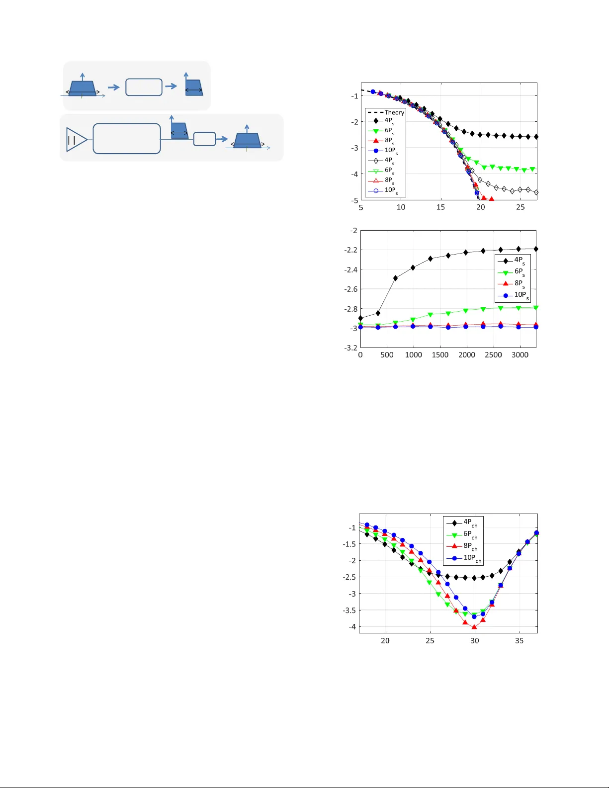
Authors: Cristian Antonelli, Antonio Mecozzi, Mark Shtaif
1 Kramers Kronig P AM transcei v er and two-sided polarization-multiple xed Kramers Kronig transcei ver Cristian Antonelli, Antonio Mecozzi, and Mark Shtaif Abstract —W e propose tw o transceiver schemes based on Kramers Kronig (KK) detection. One tar gets low-cost high- throughput applications and uses P AM transmission in combina- tion with direct detection and digital reconstruction of the optical phase. This scheme allows digital compensation of chr omatic dispersion and provides a significant improv ement in terms of spectral efficiency , compared to con ventional P AM transmission. The second scheme targets high-channel-count coherent systems with the aim of simplifying the receiv er complexity by reducing the optical components count. This scheme is based on the transmission of two SSB signals that share a transmission laser , each obtained by suppressing either optically or digitally one side of a r eal-valued signal. At the receiver , the two SSB signals are receiv ed separately , after optical de-interleaving, by KK detection, using a single local oscillator laser . Index T erms —Optical fiber communications, Modulation, Het- erodyning, Phase retrie val. I . I N T R O D U C T I O N The simplification of optical communication receivers for short and intermediate range systems has become one of the most important problems in fiber communications in the past few years. The challenge is to reduce the cost of the transceiv er with as little compromise on its performance and throughput as possible. Currently , it appears that pulse amplitude modulation (P AM) [1] is leading the race for low-cost transmission sys- tems, although significant competition has been presented by other direct detection techniques, such as the ones reported in [2]–[6]. Recently , we hav e proposed a new receiv er scheme [7] that allows the reconstruction of complex constellations from an intensity measurement requiring a single photo-diode. The method proposed in [7] relies on transmitting together with the information signal, a CW tone positioned slightly outside of the signal’s spectrum. W e hav e shown that, as soon as the intensity of the CW tone exceeds by a fe w decibels the power of the information-carrying signal [7], the ov erall electric field becomes minimum phase, implying that its complex en velope can be extracted from an intensity measurement. The implementation of the KK receiv er has been tested in the last year with a number of experimental realizations [8]–[15]. Another critical challenge that is being faced in the arena of long-haul communications is the reduction of the receiv er spatial footprint in systems where a large multiplicity of frequency and possibly spatial channels [16] are received simultaneously . In these cases, the capability of accommo- dating polarization multiplexing is an additional important C. Antonelli and A. Mecozzi are with the Department of Physical and Chemical Sciences, Univ ersity of L ’Aquila, L ’Aquila 67100, Italy . M. Shtaif is with the Department of Physical Electronics, T el A vi v Univ ersity , T el A viv 69978, Israel. requirement. While typical coherent receiv ers can accommo- date the signal multiplicity , it is quite clear that they cannot comply with the spatial footprint requirement, as the number of recei ved channels increases, unless special solutions are en visaged. In a recent paper [17], we ha ve shown that the KK transceiver can accommodate polarization multiplexing by adding the necessary CW tone at the receiv er , provided that a local oscillator (LO) is av ailable. This solution requires only two photo-diodes and no interferometric optics, versus eight photo-diodes and two optical hybrids required by an intradyne recei ver . Clearly , in this situation the use of the KK approach provides a substantial gain in terms of complexity and compactness, and in principle, it in volves no performance penalty . The polarization-multiplexed KK transceiv er is also a good candidate to reduce the spatial footprint of high- channel-count coherent receiv ers, and its use in a dense-WDM en vironment has been demonstrated recently in [10]. In this work we propose two new transceiv er schemes based on the KK approach. The first scheme addresses the former challenge of reducing the transceiv er cost and complexity in the context of short and intermediate range systems. This scheme was first presented in [18] and is reviewed here. W e call it the KK-P AM scheme, and it is based on separately modulating two field quadratures. One field quadrature con- tains a non-negati ve P AM signal, whereas the other contains its Hilbert transform, such that the overall field that is com- bined from the tw o quadratures is single-sideband (SSB). The generated SSB signal is also minimum phase, and hence it can be fully reconstructed from its intensity measurement. After the field is reconstructed, it is separated into its two original quadratures (as described later), and its in-phase quadrature is used to recover the transmitted data. The second scheme addresses more specifically the latter challenge of reducing the spatial footprint in receiv ers for medium and long-haul systems, while still addressing the receiv er complexity is- sue. W e call this scheme the two-sided (TS) KK transceiv er scheme, and it combines the spectral efficiency of the KK- P AM transcei ver with the ability to accommodate polarization multiplexing [17]. In the TS-KK scheme two SSB signals share the same transmit laser and LO, and each of them is obtained by suppressing either optically or digitally one side of a real-valued signal. At the receiver , the two SSB signals are received separately , after optical de-interleaving. In order to make this approach compatible with the optical filtering capabilities of WDM components that are av ailable today , it is necessary to introduce a small frequency gap between the spectra of two SSB signals that form a WDM channel. The paper is organized as follows. In Section II we revie w the KK-P AM transceiv er introduced in [18] and proceed 2 to its numerical validation. In Section III we illustrate the principle of operation of the TS-KK scheme, and validate it by means of numerical simulations. Section IV is dev oted to the conclusions. I I . K K - P A M T R A N S C E I V E R The principle underpinning the KK-P AM transceiv er is described in Fig. 1. W e consider an optical P AM signal p p t q “ A ` ÿ k a k g p t ´ k T q (1) where a k are zero-mean real-valued data symbols, and g p t q is the fundamental symbol waveform, which is also assumed to be real v alued, and its spectrum is symmetric and contained between ´ B { 2 and B { 2 (for Nyquist pulses T “ 1 { B ). The parameter A denotes a positiv e bias value that serves to ensure the non-negati vity of p p t q . The KK-P AM scheme relies on the transmission of the SSB version of p p t q giv en by s p t q “ A ` ÿ k a k g SSB p t ´ k T q , (2) where g SSB p t q “ g p t q ` iH t g p t qu , with H t¨u denoting the Hilbert transform. The spectrum of g SSB p t q is contained between 0 and B { 2 . At the recei ver , after filtering out-of-band noise, the optical signal is photo-detected, and the photo-current I p t q is pro- cessed according to the KK reconstruction algorithm detailed in [19]. A ke y-step in this algorithm consists of recov ering the phase φ p t q of the SSB signal s p t q by means of the relation φ p t q “ i 2 H t log r I p t qsu . (3) The reconstructed field is giv en by a I p t q exp r iφ p t qs , and it is equal to the optical field impinging upon the receiver up to a constant (time independent) phase difference. Note that the entire process of field reconstruction is performed in the digital domain. This implies that the I p t q needs to be sampled at least at its Nyquist bandwidth of B , and then digitally up-sampled so as to accommodate the bandwidth expansion implied by the logarithm of Eq. (3). An up-sampling factor of the order of two or three ha been shown to be sufficient [7], [12]. The KK procedure recov ers the dispersed version of the SSB signal s p t q , while preserving the phase of the information- carrying signal relati ve to the bias, thus making additional phase recovery unnecessary . After digital CD compensation, s p t q is recovered, and its real part yields the desired P AM signal. Since Real t s p t qu “ p p t q , the mere non-negati vity of p p t q ensures that s p t q ne ver encircles the origin in the complex plane, and hence it satisfies the minimum-phase condition underpinning the KK reconstruction procedure [19]. Y et, in the presence of chromatic dispersion, the value of A may ha ve to be increased slightly in order to guarantee that the receiv ed optical signal satisfies the minimum-phase condition. These considerations are discussed in detail in Ref. [19]. A. Numerical validation of the KK-P AM transceiver In this section we numerically validate the KK-P AM transceiv er described in the previous section. W e consider a 100 km link over standard single-mode fiber (SSMF), where we transmit a 4-P AM modulated signal using a raised cosine fundamental wa veform with a roll-off factor of 0.05, at a symbol rate of 48 Gbaud. This translates into an optical bandwidth of approximately 24 GHz for the transmitted SSB signal. In the numerical results that we present in this section, the SSB signal s p t q is assumed to hav e been produced by an I/Q modulator . The optical spectrum of s p t q if shown in Fig. 1. In the simulations, we assumed an ov erall loss budget of 26 dB and optical pre-amplification with a noise figure of 5 dB. W e then ev aluate the BER by transmitting a pseudo-random sequence of 2 15 Gray-coded symbols. At the receiv er , an optical filter with a 12th order super -Gaussian shape having a 3 dB bandwidth of 26 GHz, and centered at 16 GHz was used to remov e the excess noise. In Fig. 2a we plot the BER as a func- tion of the equiv alent OSNR, defined as OSNR eq “ P s { P n , which is the OSNR that one would measure in the absence of the bias component. Here P s denotes the power contained in the zero-mean information carrying signal ř k a k g SSB p t ´ kT q , and P n denotes the noise po wer within a bandwidth of 0.1 nm. The various curves correspond to the different bias le vels as shown in the legend, where the bias power A 2 is specified as a multiple of P s . The empty markers represent the case where CD is compensated optically prior to detection, whereas the filled markers represent the case where CD is compensated for digitally after signal reconstruction. The difference between the two cases follows from the fact that in the presence of dispersion, the non-neg ativity condition described earlier may be violated, in which case the field reconstruction is no longer perfect. This issue is notable particularly when the bias level is small, whereas in the case of a stronger bias the non- negati vity is maintained e ven for the dispersed signal and the difference between the curves plotted with the filled and empty markers vanishes. The saturation of the BER curves in the absence of optical CD compensation when A 2 “ 4 P s and A 2 “ 6 P s , follo ws from the fact that at high SNR lev els the BER is dominated by imperfect field reconstruction and hence it does not improve with power . Naturally , no saturation of the BER occurs when CD is optically compensated (empty markers). All of the curves shown in Fig. 2a comply with an FEC threshold of 10 ´ 2 . When considering the performance in terms of the equiv alent OSNR, and under the assumption of perfect reconstruction, the KK-P AM receiv er is equiv alent to a coherent receiv er , whose theoretical BER curv e [20] is plotted by a dashed line in Fig. 3. In Fig. 2b we sho w the robustness of the KK-P AM scheme to CD, by plotting the BER as a function of total CD, while assuming an equiv alent OSNR of 17 dB. The CD tolerance clearly increases considerably with the bias lev el, although even in the case where the bias is equal to 4 P s the ov erall performance is compliant with common FEC requirements. Indeed, moderate CD, as high as approximately 300 ps/nm, can be compensated digitally with no penalty in BER ev en at the lo west reported bias v alue of 4 P s . When the bias lev el is increased to 8 P s or 10 P s any value of CD 3 SSB filter ADC @ and complex field reconstruction /2 Rea l KK-P AM T ransmit ter 0 0 ⋅ /2 KK-P AM Receiv er Fig. 1. Principle of operation of the KK-P AM transceiv er . At the transmitter , one side of a non-negati ve real-valued P AM signal of bandwidth B is suppressed by means of a SSB filter (which can be implemented either in the digital domain or in the form of an optical filter). At the receiv er , the detected photocurrent is sampled with a sampling rate of B , and the SSB optical signal is reconstructed by applying the KK algorithm. The real P AM signal is obtained by taking the real part of the reconstructed signal. can be compensated digitally with no penalty . In Fig. 3 we in vestigate the performance of the KK-P AM scheme in the nonlinear regime, by repeating the simulations described in the context of Fig. 2a, with 5 WDM channels separated by 40 GHz and without optical CD compensation. The BER of the central channel is plotted as a function of the true (not the equiv alent) OSNR. The effect of the nonlinearity is seen in the form of a rise of the BER curve. Only in the case of low-bias-po wer A 2 “ 4 P s reconstruction errors precede the effect of the nonlinear distortion. B. Discussion The KK-P AM scheme should not be misinterpreted as reg- ular self-heterodyne or standard SSB transmissions, with the bias signal playing the role of a carrier . W ith these methods, the required carrier amplitude would hav e to be much larger than it is in the KK-P AM scheme. The availability of the complex signal at the end of the reconstruction makes the KK-P AM scheme equiv alent to a coherent receiver . One obvious consequence of this equiv a- lence is the possibility of digitally compensating not only for CD, but also for other propagation ef fects. Another important implication is the fact that the capacity of this scheme is close to that of a scheme using a coherent recei ver , because of the ability of the KK receiv er to detect the amplitude and phase of the signal [21]. An obvious disadvantage of the scheme described in this section is that it requires a relati vely expensi ve I/Q modulator, which is an undesirable constraint in the case of single- span low-cost systems. This disadv antage can be remedied to some extent by using a single-ended Mach-Zehnder modulator driv en with two voltages [22], although the potential of this solution for the implementation of the KK scheme is yet to be ev aluated. Another option for generating a SSB signal of the kind required by the KK procedure, is to combine an amplitude modulator with an optical filter . Howe ver , the requirements on the optical filter are very critical, and hence its implementation is not straightforward. This option is in vestigated in the section that follo ws, where we present a more spectrally ef ficient KK scheme that accommodates for polarization multiplexing. log (BER) log (BER) Equiv alent OSNR [dB] (a) (b) Chromatic disper sion [ps/nm] Fig. 2. (a) The pre-FEC BER of a 48-Gbaud KK 4-P AM system (100-km SSMF), versus the equiv alent OSNR for the displayed values of the CW bias power . Empty markers show the BER after optical CD compensation, whereas the filled markers show the BER when the CD is compensated for digitally . (b) The pre-FEC BER versus the link chromatic dispersion, for the same KK-P AM system. The curv es were obtained by keeping the power of the information carrying signal fixed, and with digital CD compensation. log (BER) OSNR[dBm] Fig. 3. The BER of the central channel of a WDM system with fi ve 40-GHz spaced KK-P AM modulated channels, versus the equiv alent OSNR (which is the OSNR that one would measure if there were no bias component in the transmitted signal). The dashed curve shows the theoretical BER of a 4-P AM coherent system impaired by A WGN [20]. 4 0 0 0 0 West - Ea st East - West Fig. 4. Original implementation of the KK scheme [7]. The west and east transmitters generate SSB signals, whose bandwidth is contained between 0 and B , where the laser frequency is 0. The west-side laser is used both for generating the SSB signal going east and as a LO for receiving the signal arriving from the east location and vice-versa. I/Q KK KK TX RX M 1 M 2 IL filt er 0 0 0 Fig. 5. Operating principle of the TS-KK transceiv er . The modulator generates a two-sideband spectrum, where each sideband contains an independent data- carrying signal. A guard-band around the center frequency ( ω “ 0 ) is inserted so as to allow separation between the two sidebands at the recei ver , where the two sidebands are optically separated and KK-processed independently and in parallel. The two reception processes make use of the same LO at ω “ 0 . I I I . T W O - S I D E D P O L A R I Z ATI O N - M U LT I P L E X E D K K T R A N S C E I V E R In this section we propose a new KK scheme inspired by the KK-P AM transceiv er that accommodates polarization- multiplex ed transmission. In order to achie ve this, we assume that the CW reference tone is av ailable as a LO at the receiving edge, and hence needs not be transmitted with the information-carrying signal. This assumption is well justified, provided that a LO can be extracted from the transmission laser that is co-located with the receiv er that performs the KK processing. In such cases the cost implications of using a LO are minimal. In the context of the KK scheme, the most straightforward implementation is illustrated in Fig. 4. The west and east transmitters generate SSB signals, whose bandwidth is contained between 0 and B , where the laser frequency is 0. The west-side laser is used both for generating the SSB signal going east and as a LO for receiving the signal arriving from the east location. Similarly , the east- side laser also serves for the two functionalities. Note that in this implementation the bandwidth of both the transmitter and receiv er must be equal to 2 B , namely twice the bandwidth of the transmitted optical signal. A modified scheme, where the bandwidth of the transmitter is reduced to B has been recently demonstrated in [10]. In that scheme the bandwidth reduction was obtained by offsetting the frequencies of the east-west channels with respect to the west-east channels, so that the information-carrying signal is always two-sided with respect to the transmission laser . Here we propose an alternativ e approach to better exploit the transmitter bandwidth while keeping it equal to the recei ver bandwidth, and without misaligning the frequencies of the east-west and west-east channels. The operating principle of the proposed approach is il- I/Q KK KK TX RX M 1 M 2 IL filter 0 0 0 Fig. 6. A different version of the same operating principle of Fig. 5. T wo single-quadrature modulators generate two real-valued signals, and a guard- band is inserted around ω “ 0 , so as to accommodate their separation at the receiv er . An interleaving filter combines the upper sideband of one signal with the lower sideband of the other . The receiver scheme is identical to that of Fig. 5. lustrated in Fig. 5. Instead of generating SSB signals as in Fig. 4, each modulator generates a two-sideband spectrum, where each sideband contains an independent data-carrying signal. A guard-band around the center frequency ( ω “ 0 ) must be programed into the system so as to allo w separation between the two sidebands on the receiv er side. The recei ver starts by optically separating the two sidebands, which are to be processed independently and in parallel by means of the KK algorithm. The two reception processes make use of the same LO positioned at ω “ 0 . As compared to SSB transmission of Fig. 4, with this approach the same transmitter is used to transmit two channels instead of one, so that its bandwidth is optimally exploited. Of course, the principle of operation described in Fig. 5 can be implemented in a WDM en vironment characterized by a multiplicity of transmitters and receiv ers. In order to a void confusion, in what follo ws we use the term WDM channel to refer to the signal generated by a single transmitter module. A slightly different version of the same operating principle is illustrated in Fig. 6. Here, two single-quadrature modula- tors generate two real-valued signals, where, similarly to the previous case, a guard-band is inserted around ω “ 0 , so as to accommodate their separation at the receiver . An interleaving filter that combines the upper sideband of one signal with the lower sideband of the other , forms the WDM signal that is to be launched into the fiber . The schemes of Fig. 5 and 6 use exactly the same receiver , but the comparison between the transmitters is interesting. The scheme of Fig. 5 relies on an I/Q modulator, which consists of two single-quadrature modulators whose outputs need to be combined in quadrature with interferometric accuracy . In the case of Fig. 6, the two single-quadrature modulators are combined in frequency and no interferometric control is required. On the other hand, an interleaving filter needs to be included. Of course, a single large interleaving filter can be shared by all WDM channels, as is illustrated in Fig. 7, in the polarization-multiplex ed case. The signals from even-inde xed and odd-indexed transmitters must be multiplexed separately first, and then interleaved by means of two interleav ers. At the receiver edge, a pair of interleav ers is needed to de-interleav e the SSB signals (of bandwidth B { 2 ) prior to de-multiplexing. 1 This is illustrated in Fig. 8. 1 W e note that in principle the role of the interleav ers and de-interlea vers can also be played by SSB filter pairs, or dichroic filters, incorporated into each transcei ver . 5 WDM MUX + IL M 1 M 2 M 3 M 4 ܤ ܤ ୰୧ୢ Fig. 7. The transmitter of the TS-KK transceiver scheme. A transmission laser is shared by two single-quadrature modulators (either amplitude modulators or single Mach Zehnder modulators), each generating a real-valued signal of bandwidth B . The two signals are multiplexed first and then interleaved. The interleav ers are off-set from the WDM grid (channel spacing B grid in the figure) so as to suppress the high-frequency (low-frequency) sideband of the signals generated by the odd-indexed (even-inde xed) modulators. De-IL + WDM MUX KK PolMux RX KK PolMux RX KK PolMux RX KK PolMux RX Fig. 8. The receiv er of the TS-KK transcei ver scheme. The recei ved WDM channels are de-interleaved first, so as to separate the low- and high-frequency sideband, and then de-multiplex ed. Each pair of SSB signals e xtracted from the same WDM channel is finally recei ved with two KK PolMux receivers sharing an LO. The KK PolMux receiver schematic is illustrated in the inset, while an extensive characterization can be found in [17]. Finally , as illustrated in Fig. 8, each pair of SSB signals originated by paired transmitters is receiv ed by paired recei vers that share a local oscillator . The sharing of the local oscilla- tor between adjacent channels was pre viously proposed for balanced heterodyne detection in [23], and applied to KK receiv ers in [13]. Clearly , the local oscillator grid used at the receiv er end is in this case aligned with that used at the transmitter . After de-multiplexing, each of the polarization- multiplex ed channel sidebands of bandwidth B { 2 together with the local oscillator is polarization-split and detected by one photodiode per polarization. The two photocurrents are sampled by two ADCs of bandwidth B . A schematic of the KK polarization-multiplex ed recei ver is shown in the inset of Fig. 8, while extensi ve descriptions can be found in [10], [17], [24]. As mentioned earlier , the guard-band around each channel’ s central frequency is needed in order to allow the combining and separation of the two sidebands. The guard-band width is determined in conjunction with the filtering capability of av ailable interleavers and de-interleav ers. When the guard- band is not sufficiently large, the residual spectral content of an imperfectly suppressed sideband falls on the wrong side of the LO, thus violating the minimum-phase condition, and thereby resulting in reconstruction errors. Frequency [GHz] Frequency [GHz] Frequency [GHz] Frequency [GHz] Frequency [GHz] Frequency [GHz] a bc d ef Intensity (A.U . – log scale) Fig. 9. Generation of a two-sided signal, as illustrated in the transmitter scheme of Fig. 7. The two spectral sides of two real-valued zero-mean 4ASK signals (a, d) are digitally shifted apart from each other (b, e). After digital- to-analog conversion, they are optically filtered with super-gaussian filters of fourth order (c, f). A. Numerical validation of the two-sided P olarization- multiplexed KK T ransceiver In this section we present a numerical validation of the TS-KK transceiv er scheme. W e transmitted two single-sided zero-mean 4ASK signals over a fiber link consisting of fiv e 100-km spans. T o this end, we first generated two real-valued 4-ASK signals at 48 Gbaud, using a raised-cosine fundamental wa veform with a roll-off factor of 0.05. W e then introduced a frequency gap B gap by moving the positive and negati ve sides of the symmetric spectra apart from each other . This procedure is illustrated in Fig. 9. W e assumed a WDM channel spacing of 80 GHz, and used filters with a forth-order super- gaussian shape, 3-dB bandwidth of 36 GHz, and 90%–to– 10% roll-off bandwidth of 7 GHz to model the interleav ers [26] (solid curves in Figs. 9b and 9e). Good performance was achiev ed by using a frequency gap B gap “ 8 . 6 GHz, while offsetting the interleav er grid by 18.8 GHz from the WDM grid. These settings yield good sideband suppression, as can be seen in Figs. 9c and 9f, with no significant increase of the necessary transmitter bandwidth, which in this case was increased from B net “ 48 GHz to B “ 48 ` 8 . 6 “ 56 . 6 GHz. At the recei ver , the two sidebands of each WDM channel were separated with the same type of filters prior to adding the CW tone. After intensity detection, we used the KK algorithm to reconstruct the single-sideband complex signal, and compensated for chromatic dispersion, as well as for the polarization rotation caused by the fiber birefringence. Finally , the original real-valued 4ASK signal was recov ered by taking the real part of reconstructed and compensated signal, after digitally removing the frequency gap. All simulations were based on the use of the Manakov equation [25] and were performed without polarization mode dispersion. A frequency- independent random polarization was applied to the optical signal prior to reception in ev ery run. Figure 10a shows the av erage BER in the linear operation regime as a function of the OSNR, for v arious intensities of the LO. The BER was e v aluated on the basis of fifty independent 6 simulation runs, each with 2 15 Grey-coded symbols, and av eraged over the two signal’ s polarizations. Solid markers refer to the 4-ASK signal encoded in the high-frequency sideband, while empty markers refer to that encoded in the low-frequenc y sideband. The solid curve is the plot of the theoretical BER for 4-ASK. In Fig. 10b we study the performance of the TS-KK transceiv er in the nonlinear operation regime. In this case, we transmitted fiv e WDM channels and measured the BER of the central channel for the same LO powers used in Fig. 10a. As detailed in [7], when the LO is relativ ely weak ( 4 P s in the fig- ure), errors at lar ge OSNR are mainly due to the reconstruction process, and hence the effect of the fiber nonlinearity is not visible. For large LO power lev els and in the limit of large OSNR, where reconstruction errors are practically absent, the effect of nonlinearity becomes dominant. W e note that in all cases considered here, the BER does not exceed the rele vant threshold of 10 ´ 3 . The TS-KK transceiver is expected to achiev e the perfor- mance of a coherent system with the same channel throughput and the same net bandwidth. In order to establish a quantitativ e comparison, we considered a 16-QAM coherent system operat- ing at 48 Gbaud and 80 GHz channel spacing. The simulation results are shown in Fig. 10b by stars, whereas the theoretical BER is still giv en by the solid curve. As is evident from the figure, for suf ficiently large LO power the dif ference between coherent and TS-KK becomes negligible. B. Complexity comparison It is interesting to conclude this section with a comparison between the hardware complexity of the TS-KK scheme and the complexity of the two most relev ant coherent communica- tions schemes; intradyne [27] and balanced heterodyne. 2 The comparison is conducted for a polarization multiplexed system and for the case where the optical bandwidth of the transmitted WDM channel is B . As we have demonstrated above, the TS- KK scheme approaches the theoretical performance limit of coherent transmission. Hence, apart from the slightly lower spectral efficienc y of TS-KK, the ultimate performance of all three schemes is identical. On the transmitter side, and restricting ourselves to typical implementations, all schemes require four optical modulators of electrical bandwidth B . In the coherent case, each modulator is responsible for mod- ulating one quadrature, while the two quadratures in each polarization need to be combined with sub-wa velength ac- curacy . In the TS-KK transmitter, each modulator modulates one sideband channel, and since the sidebands are combined in frequency domain, no interferometric accuracy is needed from the combiner . On the other hand, the TS-KK receiv er requires an optical interleaver filter , which does not exist in the coherent scheme. The comparison between the schemes on the receiv er side is summarized in T able I. All three schemes rely on the use of a 2 Here, by balanced heterodyne (or simply heterodyne) we refer to the TS- KK scheme of Fig. 8, where each of the two coupler-photodiode pairs in the KK PolMux RX block (inset) is replaced with a 50-50 bean splitter and a pair of balanced photodiodes. log (BER) log (BER) OSNR [dB] (a) (b) OSNR [dB] Fig. 10. (a) A verage BER in the linear operation regime v ersus OSNR, for the intensities of the LO shown in the legend. Solid markers refer to the 4- ASK signal encoded in high-frequenc y sideband, while empty markers refer to that encoded in low-frequenc y sideband. The solid curve is the plot of the theoretical BER for 4ASK. (b) A verage BER in the nonlinear operation regime after 500 km propagation in a SMF versus OSNR, for the intensities of the LO shown in the legend. The stars sho w simulation results for a 16-QAM coherent system. T ABLE I D E VI C E C O U N T A T T HE R E C EI V E R P E R C H A NN E L ( 2 P O L A RI Z A T I O N S ) # LDs # PDs. # ADCs # OHs Balancing Intradyne 1 8 4 2 yes Heterodyne 1 8 4 0 yes TS-KK 1 4 4 0 no Legend: LD: Laser diode; PD: Photodiode; ADC: Analog to digital con verter; OH: Optical hybrid. All devices have a bandwidth B . LO, which requires tapping the light from one laser diode (also used for transmission). The y also require the same number of ADCs, one per quadrature in the intradyne recei ver and one per sideband channel in the case of heterodyne and TS-KK. The intradyne receiver requires two optical hybrids, one per polarization, whereas in the case of the heterodyne and TS- KK receivers, no optical hybrid is required. The number of photodiodes is eight in the case of the coherent receiv ers, as differential detection requires two balanced photodiodes per ADC. In the TS-KK receiv er only four photodiodes are required — one for each sideband channel. On the other hand, the TS-KK recei ver requires an e xtra interlea ver , whose resolution requirements are higher than in the coherent case. W e note ho wever , that the cost of the extra interlea vers 7 required by the TS-KK scheme (at transmitter and recei ver), is shared by all of the WDM channels. I V . C O N C L U S I O N S W e hav e introduced two new approaches for implementing the KK field-reconstruction procedure in fiber-optic systems. W e called them the KK-P AM and the TS-KK configurations. The KK-P AM scheme is similar to KK scheme in which the CW tone is combined with the data-carrying signal at the transmitter [8]. Its uniqueness is in the fact that it relies on the transmission of SSB P AM signals. The launched signal can be constructed digitally , by dri ving an I/Q modulator , or optically , in which case a single-quadrature modulator is used in combination with optical filtering. The TS-KK scheme relies on the availabi lity of a LO at the receiver and its main advantage over KK-P AM (or the KK scheme of [8]), is in the fact that it can readily accommodate polarization multiplexing. Its construction is such that the LO can be extracted from the transmit laser that is present at the same location. The performance of the TS-KK is similar to that of typical coherent receiv ers, with the only drawback that a guard-band that allows the separation between sidebands needs to be included in the transmitted spectrum, thereby reducing the spectral efficienc y . W e hav e seen that with reasonable assumptions on the av ailable components, the reduction of spectral efficiency is only within 15 percent. The adv antage of the TS-KK scheme in comparison with coherent communications schemes, is in the absence of optical hybrids and in the fact that the outputs of the individual modulators at the transmitter need not be phase-controlled when combining them into a single fiber . In addition, the necessary number of photo-diodes is smaller by a factor of two, and no balancing is required. The disadv antage is the need of optical filtering, but the implied extra cost is shared by all WDM channels. Finally , it is worth pointing out that the TS-KK scheme is also suitable for medium-to-long haul transmissions, owing to the fact that the information- carrying signal is transmitted without a CW tone, which would be responsible for power inefficienc y and extra nonlinear penalties. A C K OW L E D G E M E N T C. Antonelli and A. Mecozzi acknowledge financial support from the Italian Gov ernment under Cipe resolution n. 135 (Dec. 21, 2012), project INnov ating City Planning through Information and Communication T echnologies (INCIPICT). Mark Shtaif acknowledges the support of the Israel Science Foundation Grant No. 1401/16. R E F E R E N C E S [1] N. Eiselt et al. “First Real-T ime 400G P AM-4 Demonstration for Inter- Data Center Transmission over 100 km of SSMF at 1550 nm, ” Proc. of OFC 2016, Paper W1K.5 (2016). [2] S. Randel, F . Breyer , S.C.J. Lee, and J.W . W alewski, “ Adv anced Modu- lation Schemes for Short-Range Optical Communications, ” IEEE J. Sel. T opics Quantum Electron. 16 , 1280–1289 (2010). [3] A.J. Lowery and J. Armstrong, “Orthogonal-frequency-division multi- plexing for dispersion compensation of long-haul optical systems, ” Opt. Express 14 , 2079–2084 (2006). [4] B.J.C. Schmidt, A.J. Lo wery , and J. Armstrong, “Experimental Demon- strations of Electronic Dispersion Compensation for Long-Haul T rans- mission Using Direct-Detection Optical OFDM, ” J. Lightwav e T echnol. 26 , 196–203 (2008). [5] M. Schuster , S. Randel, C.A. Bunge, S.C.J. Lee, F . Breyer, B. Spinnler, and K. Petermann, “Spectrally Efficient Compatible Single-Sideband Modulation for OFDM T ransmission With Direct Detection, ” IEEE Photon. T echnol. Letters 20 , 670–672 (2008). [6] S. Randel et al. “100-Gb/s Discrete-Multitone Transmission Over 80- km SSMF Using Single-Sideband Modulation With Novel Interference- Cancellation Scheme, ” Proc. of ECOC15, Paper 0697 (2015). [7] A. Mecozzi, C. Antonelli, and M. Shtaif, “KK coherent receiver , ” Optica 3 , 1220–1227 (2016). [8] X. Chen, C. Antonelli, S. Chandrasekhar, G. Raybon, J. Sinsky , A. Mecozzi, M. Shtaif, and P . W inzer , “218-Gb/s Single-W avelength, Single-Polarization, Single- photo-diode T ransmission Over 125-km of Standard Singlemode Fiber Using Kramers-Kronig Detection, ” in Op- tical Fiber Communication Conference, OSA T echnical Digest (online) (Optical Society of America, 2017), post deadline paper Th5B.6 [9] Z. Li, S. Erkilinc, K. Shi, E. Sillekens, L. Galdino, B. Thomsen, P . Bayvel, and R. Killey , “SSBI Mitigation and Kramers-Kronig Scheme in Single-Sideband Direct-Detection T ransmission with Receiver-based Electronic Dispersion Compensation, ” J. Lightwav e T echnol. 35 , 1887– 1893, (2017). [10] X. Chen, C. Antonelli, S. Chandrasekhar , G. Raybon, A. Mecozzi, M. Shtaif, and P . Winzer , “4 ˆ 240 Gb/s Dense WDM and PDM Kramers- Kronig Detection with 125-km SSMF Transmission, ” ECOC 2017, paper W .2.D.4 (2017). [11] Z. Li, M. S. Erkilinc, K. Shi, E. Sillekens, L. Galdino, B. Thomsen, P . Bayvel, and R. Killey , “168 Gb/s/l Direct-Detection 64-QAM SSB Nyquist-SCM Transmission over 80 km Uncompensated SSMF at 4.54 b/s/Hz net ISD using a Kramers-Kronig Receiver , ” ECOC 2017, paper T u.2.E.1 (2017). [12] Z. Li, M. S. Erkilinc, K. Shi, E. Sillekens, L. Galdino, B. Thomsen, P . Bayvel, and R. Killey , “Joint Optimisation of Resampling Rate and Carrier-to-Signal Power Ratio in Direct-Detection Kramers-Kronig Receiv ers, ” ECOC 2017, paper W .2.D.3 (2017). [13] S. Fan, Q. Zhuge, M. Sowailem, M. Osman, T . Hoang, F . Zhang, M. Qiu, Y . Li, J. W u, and D. Plant, “T win-SSB Direct Detection Transmission over 80km SSMF Using Kramers-Kronig Receiv er , ” ECOC 2017, paper W .2.D.5 (2017). [14] S. T . Le, K. Schuh, M. Chagnon, F . Buchali, R. Dischler, V . Aref, H. Buelow and K. Engenhardt, “8 ˆ 256Gbps V irtual-Carrier Assisted WDM Direct-Detection Transmission over a Single Span of 200km, ” ECOC 2017, paper Th.PDP .B.1 (2017) [15] X. Chen, J. Cho, S. Chandrasekhar, P . J. Winzer , C. Antonelli, A. Mecozzi, and M. Shtaif, “Single-W avelength, Single-Polarization, Single-Photodiode Kramers-Kronig Detection of 440-Gb/s Entropy- Loaded Discrete Multitone Modulation T ransmitted over 100-km SSMF , ” IEEE Photon. Conference 2017, paper PD1 (2017). [16] D. Soma et al., “10.16 Peta-bit/s Dense SDM/WDM transmission over Low-DMD 6-Mode 19-Core Fibre across C+L Band, ” ECOC 2017, paper Th.PDP .A.1 (2017). [17] C. Antonelli, A. Mecozzi, and M. Shtaif, X. Chen, S. Chandrasekhar , and P . J. Winzer , “Polarization multiplexing with the Kramers Kronig receiv er , ” J. Lightwave T echnol., to appear . [18] C. Antonelli, A. Mecozzi, and M. Shtaif, “Kramers-Kronig P AM T ransceiv er , ” in Optical Fiber Communication Conference, OSA T ech- nical Digest (online) (Optical Society of America, 2017), paper Tu3I.5. [19] A. Mecozzi, “ A necessary and sufficient condition for minimum phase and implications for phase retriev al, ” (2016) available at http://arxi v .org/ abs/1606.04861 [20] J.G. Proakis, Digital Communications, McGraw-Hill series in electri- cal and computer engineering: communications and signal processing, Chapter 5, Section 2-9, McGrawHill, 4th edition (2001). [21] A. Mecozzi and M. Shtaif, “Information capacity of direct detection optical transmission systems, ” submitted to J. Lightwav e T echnol. [22] Liang Zhang, Tianjian Zuo, Y uan Mao, Qiang Zhang, Enbo Zhou, Gordon Ning Liu, and Xiaogeng Xu, “Beyond 100-Gb/s Transmission Over 80-km SMF Using Direct-Detection SSB-DMT at C-Band, ” J. Lightwav e T echnol. 34 , 723–729 (2016). [23] Xinying Li, Jianjun Y u, Nan Chi, Ze Dong, Junwen Zhang, and Jianguo Y u, “The reduction of the LO number for heterodyne coherent detection, ” Opt. Express 20, 29613-29619 (2012). [24] X. Chen, C. Antonelli, S. Chandrasekhar, G. Raybon, A. Mecozzi, M. Shtaif, and P . Winzer , “Kramers-Kronig Receiv ers for 100-km Datacenter Interconnects, ” submitted to J. Lightwav e T echnol. 8 [25] D. Marcuse, C. R. Menyuk, and P . K. A. W ai, “ Application of the Manakov-PMD equation to studies of signal propag ation in optical fibers with randomly varying birefringence, ” J. Lightwav e T echnol. 15 , 1735– 1746 (1997). [26] T ypical spectral profiles of interleavers can be found at: http://www .optoplex.com/download/Optople x%20Optical% 20Interleav er%20Brochure%20Rev1.3.pdf [27] K. Kikuchi, “Fundamentals of Coherent Optical Fiber Communications, ” J. Lightwa ve T echnol. 34, 157-179 (2016).
Original Paper
Loading high-quality paper...
Comments & Academic Discussion
Loading comments...
Leave a Comment