A Novel Detection Algorithm Efficient for Turbo coded CDMA Signals in Detect and Forward Cooperative Channels
In this paper, a new detection algorithm is proposed for turbo coded Code Division Multiple Access (CDMA) signals in detect and forward cooperative channels. Use of user cooperation makes much improvement in the performance of CDMA systems. Due to th…
Authors: Ebrahim Karami
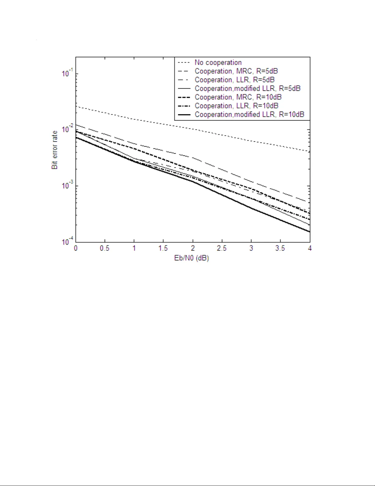
A Novel Detect ion Algorithm Efficient for T urbo coded CDMA Signals in Det ect and Forwa rd Coop erative Channe ls Ebrahim Karami Centre for Wireless Communications (CWC), University of Oulu, P.O. Box 4500, FIN-90014, Oulu, Finland Abstract — In this pape r, a new detection algorithm i s proposed for turbo coded Code Division Multip le Access (CDMA) signals in detect and forward cooperative channels. Use of user cooperation mak es much improvement in the perform ance of CDMA systems. Due to the special structure of CDMA systems, cooper ativ e schemes increase the sum and cutoff capacities of CDMA based wireless systems and improve the quality of user - partner link which enhance s the overall performance of the system . In this paper, a new com bining scheme is proposed that makes the rece iver more robust ag ainst the decision errors in the partner link. T his structure is simulated for punctured ½ rate 4 states tu rbo code in a channel w ith first order Mark ov tim e variatio n and differen t Rice factor variances. Through v arious simulations, it is shown when the channel estimates are available in the partner and receiver, t he cooperation b etween users prov ides much diversity gain especial ly while using t he new proposed combining alg orithm. Keywords — CDMA, co operativ e diversity, convoluti onal codes, log likelihood r atio, partner selection set. I. INTRODUCTION In a wireless channel, fading is the most important limiting factor for mobi lity and consequently sum and cutoff capacity of m obile users. To combat the fading effects, diversi ty techniques are proposed. Diversity is to receive multiple copies. Diversity t echniques can be classified into transmit [ 1], receive [2 ], time [3], frequency [4], code [5], space and polarization diversit y [6] . Ex cept for space div ersity , the other techniques provide diversity gain at the cost of reduction in sum capa city. I n the rece nt years, antenna arra y s and their extension as Multiple-Input Multiple-Output (MIMO) systems have gained interest in improving capacity and mobility in mobile wireless chann els under severe fading effects [7]. Due to the ph y sical limitation in the handsets, use of antenna array in them is impractical, especiall y in lower frequenc y bands corresponding to long wave lengths. Ac cording to the Lee model [8] for wireless fading chann els, the mi nimum required space between elements of an array in a handset is 2 . 0 where is the wavelength of carrier that is abou t 6.7cm and 3.1cm in t he second and third generations o f wirel ess standards, respect ively . Therefore, application of antenna arrays is restricted to base stations where size-limitation is less important than in the handset. Use of cooperation between us ers in the tr ansmission process is an ef ficient solut ion for the above problem [9]. In a cooperative wireless commu nication, unlike the usual antenna arrays, the link between elements of ant enna array is wireless. Therefore, the cooperative channels are so called virt ual arrays or distributed antenna arra y s y stems. In common antenna arra y s b ecause of wired li nks between the array elem ents, the problems related to attenuation and bandwidth of these links don’t exist and therefore the s y stem can be designed with simplicity. In the cooperative s y stems, the quality of user- partner link h as a great influence on the performance of the s ystem [1 0, 11]. There are sev eral cooperation signaling methods such as detect and forward, amplif y and f orward, and coded cooperation [12]. I n detect and forward cooperative channels which is ver y close to tradition al relaying idea, data received by partner is dete cted and th en its modulated again and transmitted toward main receiver. Therefore this new transmitted data suffers from dec isions errors occurred in the partner link. The use of CDMA as an access technique not only solves the above problem [ 13], but also eliminates the need for additional wireless channel for user-partner link. On the other hand, while using CDMA, the requirement of precise timing between user and partner transmission time-slots is circumvented. In all ex isting researches o n the cooperative systems, especially for detect and forward schemes, in the design of the r ece iver, t he decision errors occurr ing in pa rtner link are i gnored. Using turbo codes in cooperative s y stems is proposed to approa ch the capacity achievable by relay based channels [1 4-16]. In this paper, in addition to simulation of the turbo coded cooperative based mul tiuser CDMA; for ti me varying channels b y considering the effect of partner selection set siz e and Ricean factor of users in cell, a new combining sc heme is proposed to make the performance of th e receiver more robust to the decision errors occurring in partner link. The rest of this paper is organized as follows. In Section II, the models used for signal, spreading, a nd time varying channel are introduced. In Se ction III, the receiver structures with different combining schemes are introduced. In Section IV, the simulation results for the prop osed receiver are presented, and the concluding remarks are presented in Section V. II. SYSTEM MODEL A. Signal Model Assume k b as d ata s ymbol coming from dat a source at time index k . As shown in Fig. 1, each user encodes data s y mbols k b by a punctured turbo encoder with rate of ½ as shown in Fig. 2 and then its corresponding output symbol, k d , that has two bits 1 2 k d and k d 2 as its elements are spread b y the spreading sequence 1 s which is a c N 1 vector as follows 1 0 2 1 2 , i , d i k i k s t , (1) where i k 2 t is c N 1 transmitted vector in time index k . As illustrated in Fig. 3, a copy of this signal is received by a pre-selected partner as follows, 1 0 2 2 2 2 , i , I h i k , p i k , p i k k , in i k , p w t r , (2) where i k , p 2 r is the received vector b y the partner, i k , p I 2 and i k , p 2 w are multiple access interference and AWGN noise, respectively, in the front end of the partner r ece iver, a nd k in h , is the user-partner coefficient that is scal ar due to single-antenna assum ption for users. The received vector is despreaded by the following equation and decoded by the turbo decoder. The block di agram of the turbo decoder is shown in Fig. 4. 1 0 2 1 2 , i , i k , p H i k , p r s y , (3) where the superscript H is the conjugate transpose operator and i k p 2 , y is the output of the desp reader. For each user, a partner selection set is defined. The size of thi s set depends on the required privacy degree. The members of this set are so called the friends of user and ha ve full access to the data of user. Of cours e to overcome this limitation, encryption algorithms can be considered but this issue is not of interest and thus not regarded in the scope of thi s paper. The partner is chosen to have the best quality propagation env ironment to the user. Partner can be selected b y man y criteri a the most common of which is the neare st use r in cell [ 18]. In this paper, as a result of the t im e varying natur e of the channel due to the movement of the users, the partner is selected as such to have the largest LoS component. Therefore, the user-partner link is usually Ricean with hi gh enough SNR and Ricean factor. Thus, the data detected by the partner is very close to the original transmitted coded data. The detected data, k ˆ d , that has two bits 1 2 k d ˆ and , k d ˆ 2 as its elements is then spread by the spreading sequence 2 s and retransmitted to the receiver as follows, 1 0 2 2 2 , i , d ˆ i k i k , p s t , (4) where i k , p 2 t is c N 1 vector transmitted by the partn er. Of course, in this section onl y the detection of the coded transmitted signal is performed and t o keep the s ync hronization of user and partner the decoding and re-encoding of the coded signal is ignored. Consequently , the lack o f synchronization observed between user a nd its partner can be n egligible and ignored to reduce the complexit y in the design of the combining algor ithm at the receiver side. In the receiver side, the sum of two copies of the signal transmitted b y user and its partner, interference vector i k 2 I due to the other users and their p artners using the same frequency band, and AW GN noise k w is received in N elements of receiver array as follows, 1 0 2 2 2 2 2 , i , i k i k i k , p k , p i k k , u i k w I t h t h r , (5) where k , u h and k , p h are 1 N vectors of channel co eff icients for user-receiver and partner-receiver, respectively, where N is the number of the receiver ar ray elements. Therefore i k 2 r , i k 2 I , and i k 2 w are c N N matrices. B. Time Variation Model of the Channel Due to the short distance between user and partner, the user-partner link is a Rice an channel that is a combination of a constant part and a time vary ing part as the following equation. k , in , in k , in h ~ h h 0 , (6) where 0 , in h is the nearly cons tant part which can be due to the L oS components that are fairly constant in a long block of the data, and k , in h ~ is the time varying part which is mainl y due to the No-LoS (NLoS) components. Because of a relativel y long distance between user and its partner to b ase station the corresponding channel coefficients, same as time-varying part, are severely v ariable in the duration of data block transmission with the autocorrelation that follows the following equation [18] p , u m , l k T f J h h E , l k T f J h ~ h ~ E i D , m * i l , m i k , m D , in * l , in k , in 2 2 0 0 , (7) where i k , u h and i k , p h are i th elements of k , u h and k , p h or in other word the channe l coefficients between user and its par tner, respectively, to i th elements in base station receiver, . J 0 is the zero- order Bessel fun ction of the first kind, super script * denotes th e complex conjugate, D , in f is the Doppler frequenc y shift between transmitter and partner, i D , u f and i D , p f are Doppler frequency shift between transmitter and its partner, respectively, to i th elements in base station receiver, and T is the duration of e ach s y mbol. According to the Wide Sense Stationary Uncorrelated Scattering (WSSUS) model of Bello [1 9], all the channel taps are independent, namel y , k , u h and all i k , u h s and i k , p h s vary independently, according to the autocorrelation model of (7). The no rmalized sp ectrum for each tap k , in h ~ is . ot he rwi se , T f f , f f T f f S D , in D , in D , in k , in 0 1 1 2 . (8) The ex act modeling of t he vector process k , in h ~ with a finite length Auto-Re gressive (AR) model is impossible. For implementation of a channel estimator, MIMO chan nel variations k , in h ~ and i k , u h s and i k p h , s can be approximated by the following AR process of order L N ,..., , i and p , u m , v h h , v h ~ h ~ i k , m L l i l k , m i l , m i k , m k , in L l l k , in l , in k , in 2 1 1 1 , (9) where l , in , i l , u s, and i l , p s are the l th coefficients in AR models of k , in h , i k , u h s and i k , p h s and k , in v , i k , u v s, and i k , p v s are zero-mean i.i.d. complex Gaussian processes with variances given by N ,..., , i and in , p , u m , v v E i k , m v * i k , m i k , m 2 1 2 . (10) For the optimum selection of channel AR model para meters from correlation functions, Wiener equations can be used applying the L following equations . ,...,k L L,k k t ,...,N , i , i , p , u m , t l k T f J t k T f J L l l , m D , m D , m 1 1 2 1 2 2 an d 1 0 0 (1 1) The len g th o f the ch annel model must be chosen to a minim um of 90% of the energ y spectrum of each channel coefficients contained in the frequency range of T f f D , m . The speed of channel v ariations is depende nt on the Doppler shift, or equivalentl y on the relative velocity between the receivers and the transmitter eleme nts. A rea sonable assumpti on, which is conventional in most of the scenarios, is the equal Doppler shifts D , u i D , u f f and D , p i D , p f f for the elements of the receiver array. The refore, channel coefficients for user and its partner to the array of the base station can be rewritten in vector f orms as the following equation p , u m , k , m L l l k , m l , m k , m ν h h 1 , (12) where k , u h and k , p h are the channel vectors and l , u s and l , p are the co efficie nts of order L of the AR channel model variati ons that can be calculated from (4) which for first order channel model, by solving Wiener equation, the values of the u and p are calculated as p , u m , T f J D , m m 2 0 . (13) It is obvious that the larger Doppler ra tes leads to the small er and, therefore, faster c hannel variations. III . THE RECEIVER DES I GN The block diagram of the rece iver is shown in Fi g . 5. As it can be seen, the main part of the receiver is combining block wh ere the signal received directl y and indirectly f rom user and partner , respectivel y , must be combined. I n this paper, 3 combining algorithms are present ed to combine the signals received from the user and the partner. The first two algorithms are the max imum ratio combining (MRC ) and the log likelihood ratio ( LL R) detection that are well-known algorithms in the communications literature, and the third algorithm is constructed by certain modifications in the LLR algorithm. A. The MRC Algorithm In a MRC combiner the receiver uses a two dimensional Rake receiver as follows. All the signals received b y N elements of the receiver array is despread by match ed filters corresponding to spreading sequences used in user and partner independently by 2 1 1 0 2 2 , j , , i , H j i k i k , j s r y . (1 4) Then b y emplo y ing th e max imum ratio combiner, the 2 N outputs of the matched filters are combined and fed into the turbo decoder. 1 0 2 2 2 1 2 , i , L y i k , H k , p i k , H k , u C i k y h y h , (1 5) where i k , j 2 y are the N output s of the match ed filters, with 2 elements for each, i k y 2 is the output of the max imum ratio combiner which is a two elements vector, and C L is the scaling factor required b y turbo decoder which for I N interfering user is defined as follows, c I w C N N L 2 2 . (1 6) The denominator of (16) denotes the variance of equivalent noise plus interference i.e. 2 e when the random spreading is used c I w e N N 2 2 . (1 7) It must be noted that the propagation vectors k , u h and k , p h are assumed to be known in the receiver. Also, the inter-user link coefficient is assumed to be known for the partner. B. The LLR Algorithm The LLR of each received symbol can be calculated as follows, 1 0 1 1 2 2 2 2 2 , i d Pr d Pr y i k i k i k i k i k r r , (1 8) where . . Pr presents the conditional probability. By appl y ing the Ba y s theorem, then 1 1 1 1 2 2 2 2 2 2 2 i k i k i k i k i k i k i k d Pr d Pr d Pr d Pr y r r . (19) We assume, there is not any initial knowledge about the transmitted symbols, there fore 2 1 1 1 2 2 / d Pr d Pr i k i k . (20) Then by applying (1), (4), (5), and (20) in (19) and assuming correct decisions in partner side i.e. i k d ˆ 2 = i k d 2 , we have, 2 2 1 2 2 2 2 1 2 2 2 2 1 2 1 s h s h r s h s h r k , p k , u i k eq k , p k , u i k eq i k exp exp y . (21) The output of (21) must be applied to the turbo decoder direc tl y and without any scaling . C. The Modified LLR Algorithm In the conventional method for calculation of LLR and MR C methods, we get an assumption on the completely correctness on dec isions in partner side. This assumption can be destructive esp ecially when the user-partner link has low quality . Hence, certain modifications in calculation of LL R defi ned in (18) ar e introduced as follows, . d d ˆ Pr d ˆ , d Pr d d ˆ Pr d ˆ , d Pr d Pr i k i k i k i k i k i k i k i k i k i k i k i k 1 1 1 1 1 1 1 1 1 2 2 2 2 2 2 2 2 2 2 2 2 r r r (22) . d d ˆ Pr d ˆ , d Pr d d ˆ Pr d ˆ , d Pr d Pr i k i k i k i k i k i k i k i k i k i k i k i k 1 1 1 1 1 1 1 1 1 2 2 2 2 2 2 2 2 2 2 2 2 r r r (23) By defini ng c P and e P as the probability of correct and incorrect symbol detection in the partner side, respectively, we have, 1 1 1 1 2 2 2 2 i k i k i k i k c d d ˆ Pr d d ˆ Pr P , (24) c i k i k i k i k e P d d ˆ Pr d d ˆ Pr P 1 1 1 1 1 2 2 2 2 . (25) Consequently by applying (24) and (25) in (22) a nd (23) the modified LLR is calculated as follows, c k , p k , u i k eq e k , p k , u i k eq e k , p k , u i k eq c k , p k , u i k eq i k P exp P exp P exp P exp y 2 1 2 2 2 1 2 2 2 1 2 2 2 1 2 2 2 2 1 2 1 2 1 2 1 s h s h r s h s h r s h s h r s h s h r . (26) The main problem of the proposed algorithm is th at it should know the val ue of e P or equivalentl y c P which can be variable d ependent to the qualit y of the user partner li nk. Thi s problem can be solved b y considering a pre-determined decision error probabil ity in the partner side. As it can be seen in the next Section, by considering a fix ed value for the e P c an noticeably improv e the performance of the conventional LLR method in a wide ra nge of channel conditions. IV. SIMULATION RESULTS The proposed structure is s imulated by Mont e Carlo simulation technique. In this paper, a punct ured turbo encoder with 4 states recursive convolutional encoders with generator connection matrix [1 0 1; 1 1 1] is used. E ach user and its partner use different spreading sequences. Random codes are considered as sp reading sequences. 50 chips random sequences are an efficient model for the l ong codes used in 3G mobi le communications. On t he other hand, b y the use of random spreading the number of codes can be much more than the spreading l ength. The number of antenna in all users is assumed to be 1 and BS is assumed to be sup ported by a 3 -element array. The e P used in all th e simulations is experimentally assumed to be 0.025 as it r esponded well in all the sim ulations ma de. Th is sy stem is simulated in the multiuser case with 50 and 100 int erf ering users, of course half of the numbers is dedicated to partners, consequently 50 and 100 interfe ring users correspond to half and full rank CDMA s ystems. T he maximum number co nsidered for the interfering users is twice than the spreading len g th which is equivalent to full load condition. All users are assumed to be uniformly distributed inside of a circle, and power control is assumed to be used in BS to compensate for the s low fading obse rved in all user-BS links. Therefore, as introduced in the channel model Section, the averaged received power from each user in BS can be assumed to be unity. The ex act modeling of the user-partner links is very complicated, but in this paper we assume the y are Ricean channels with log- normal distributions with R =5 and 10dB v ariances dependent on the densit y of the buildings and other obstacles in the propagation environment. All users are assumed to have random displacement velocities and correspon ding T f D s are considered to have uniform distributi on in [0 0.04] . Of course, it must be noted that uniform dist ribution for T f D s corresponds to the uniform distribution for users’ velocities. The simulation results are presented in Figs. 6 to 9 for which Figs. 6-7 correspond to when the partner selection set is confined to 10 users, and Figs. 8-9 to an unlimited partner selection set size. Also Figs 6 and 8 are for a half load s y stem which Figs. 7 and 9 are for a full load channel. In all cases, use of cooperation provides noticeable gains over non-c oopera tion c ase with much lower BER floors. In all simulation with higher value of the Ricean factor va riance , i.e. when R =10dB, much better performances can be achieved. This is due to the better qualit y of the best partner selected among the members in the partner selection set. I n other word s, in this case, partner c an be selected f rom a wider range of partners Ricean factors. Also, equivalently with a larger partner selection set siz e i.e. when there is not any limiting assumption on the partner selection set size much better performances can be achieved. Also, in all cases, out of the 3 combining schemes, the proposed alg orithm i.e. the modified L LR based combining presents the best performance and the MRC algorithm presents the worst performance. In BER= 3 10 , th e additional perf ormance gain achieved b y the modi fied LLR as compared to th e conventional LLR varies in range of 0.2dB, in F ig 6 when R= 5dB, to 0.6dB, in Fig 9 when R=10dB. V. CONCLUSION In this paper, performance of the turbo coded Code Division Multiple Access (CDMA) based on cooperation between users in the presence of sy mbol by symbol time varying R ay leigh fades is evaluated. Also, a new modified LLR based co mbining scheme is presented to combine the signals received from user and partner side. This algorithm is compared to the MRC and the conventional LLR based algorithms. Th e system is simulated for a punctured turbo coded structure wit h 4 states recursive convolutional encoder with generator connection matrix [ 5 7]. The data s y mbols are spr eade d b y 50 chips random spreading sequence s after encoding. In multi-user operation, the maximum of 100 interfering users are considered corresponds to a 100 percent load. All users are assumed to be uniformly distributed inside of a circle and the power control is assumed to be used in the BS to compensate for the slow fading observed in all user-BS links. I n all simulations, Ra y leigh channels are considered for both user-receiver and partner-receiver li nks and the inter-user links are considered to be Ricean with different Ricean factors with log -normal distribution. All li nks are considered as fast fading i.e. their coefficients vary symbol by symbol in the duration of a data block. It is shown that in all ca ses, use of cooper ation provides noticeabl y high gains over non-cooperat ion ca se s. Also, it is show n that in all simulations with higher v alue of the Ricean f actor variance or a larger partner selection set siz e, much better performances c an be achieved. This is due to the better quality of the best pa rtner selected among the m embers of the partner sele ction set. Also in all cases, out of the 3 considered combining schemes, th e proposed algorith m pr esents the best performance while the MRC algorithm presents the worst performance. REFERENCES [1] C. Van Rensburg and B . Friedlander, “Transmit diversi ty for arrays with correlated Raylei gh fading,” i n proceedings o f the Thirty-Fou rth Asilomar Conference on Signals, Systems a nd Computers, vol. 1, 29 Oct. -1 Nov. 200 0, pp. 301- 305. [2] F. R. Farro khi, K. J. R. Liu, and L. T assiulas, “ Transmit a nd receive di versity and equa lization in wirele ss networks with fadi ng cha nnels,” in proceeding s of IEEE Global Telecommun ications Conference, Globecom 97 , Vol. 3 , 3-8 Nov. 1997, pp. 1193 -1198. [3] A. M. D. Turkmani a nd A. F. de Toledo, “Time d iversity for digital mobile radio,” in proce edings of IE EE 40 th Vehicular Techn ology Conference , 6 -9 May 1990, p p. 576- 581. [4] M. Lu gli o, “Fade countermeasures in Ka band: ap plication of frequency d iversity to a satellite syste m ,” i n proceed ings of Tenth In ternational Conference on Digital Satellite Commu nications , vol. 1, 15-19 May 1995, pp. 143-151. [5] K. I l- Min and V. Taro kh , “ Variab le- ra te space-ti me block codes in M - ary PSK systems, ” IEE E Journa l on Selected Areas in Communica tions, Vol. 21 , no. 3, pp. 362-373, Apr. 200 3. [6] M. Kar and P . Wahid, “ T w o- branch space and polarization diversity sche m es for dipoles,” in pro ceedings of IEEE Antenna s and Propagation Society International Symp osium , Vol. 3, 8-13 Jul. 2001 , pp. 364- 367. [7] G. J. Foschini and M. J . Gans, “On limits o f wireless communications in a fading envir onment when using multiple antennas,” W ireless Persona l Communications , vol. 6, no. 3, pp. 331 -335, March 1998. [8] P. Van Rooyen, M. P. Lotter, and D. Van W yk , Space-Time Proce ssing fo r CDMA Mobile Communications , Kluwer Ac ade mic Pub., 2000. [9] A. Sendo naris, E. Erkip, and B. Aazhang, “Increa sing uplink capacity via user cooper ation diversi t y,” in Proceedin gs IEEE In ternational Symposium on I nformation Theory, ISIT2006 , Cambridge, MA, August 1998, p . 156. [10] A. Ste fanov and W. Erkip, “ Coop erative space- time coding for wireless networks,” in proceeding s of 2003 IEEE Information Th eory Workshop , 31 March-4 April 2003, pp. 50 - 53. [11] A. Sendonaris, E. Erkip, an d B. Aazhang, “ User cooperation diversity - Part I: System descr iption,” IEEE Trans. Commun. , vol. 51, pp.1927-1938 , Nov. 2003. [12] A. Nosrati nia, T.E. Hunter, and A. Heda y at, “Coop erative Communicat ions in W ireless Networks,” IE EE Commun., Magazine, vol. 42, no. 10, pp74 -80, 2004. [13] E . Karami, M. Shiva, and M. Abtahi, “Coded CDM A in Coo perative Channel,” in Proceed ings of 61st IEEE Veh icular Technolog y Conference, VTC Spring 2005 , Stockholm, Sweden, 3 0 May-1 June 2005, pp. 310- 313. [14] B . Zhao and M. C. Valenti, “Distributed turbo coded diversity for the rela y channel,” I EE Electronic letters, vol. 39, no. 10, pp. 786 -787, May 2003. [15] M. C. Valenti and B. Zhao, “Distributed turbo codes: Towards the capac i ty of the relay cha nnel,” in Proc. IEEE Vehicular Tech. Conf., VTC2003, Orlando, Fl., Oc. 2003. [16] B. Zhao and M. C. Valenti, “Cooper ative diversity using distributed turbo codes,” in P roc. Virginia Tech Symp. On Wireless Persona l Commun., June 2003 . [17] Z. Lin , E. Erkip, and A. Ste fanov, “Coo perative Regions and P artner Choice in Coded Cooperative Systems IEEE Trans. on Co mmun. , April 2006, pp. 760 - 760. [18] W. C. Jakes Jr., Microwave Mobile Commu nications . J ohn Wiley & Sons, NY, 1 974. [19] P. A. Bello, “ Characterization o f randomly ti me- variant lin ear channels,” Trans. On Communication Systems, vol. CS- 11, Dec. 1963, p p. 360- 393. Fig. 1. The block diagram of the transmitter + + D D + k b 1 , k d 2 , k d Interleaver + + D D + Puncturing Fig. 2. Block diagram of turbo encoder Fig. 3. The partner block diagram + + Decoder 1 Decoder 2 Interleaver Soft Inputs Systematic part Parity 1 Parity 2 De- Interleaver Interleaver Fig. 4. Turbo decoder block diagram Fig. 5. The BS receiver block diagram Fig. 6. Comparison of the cooperative system with diffe rent combining algorithms for 50 active users and 10 members in partner sets. Fig. 7. Comparison of the cooperative system with diffe rent combining algorithms for 100 active users and 10 members in partner sets. Fig. 8. Comparison of the cooperative system with diffe rent combining algorithms for 50 active users and no limitation on partner selection set. Fig. 9. Comparison of the cooperative system with diffe rent combining algorithms for 100 active users and no limitation on partner selection set.
Original Paper
Loading high-quality paper...
Comments & Academic Discussion
Loading comments...
Leave a Comment