Analysis and Rate Optimization of GFDM-based Cognitive Radios
Generalized frequency division multiplexing (GFDM) is suitable for cognitive radio (CR) networks due to its low out-of-band (OOB) emission and high spectral efficiency. In this paper, we thus consider the use of GFDM to allow an unlicensed secondary …
Authors: A. Mohammadian, M. Baghani, C. Tellambura
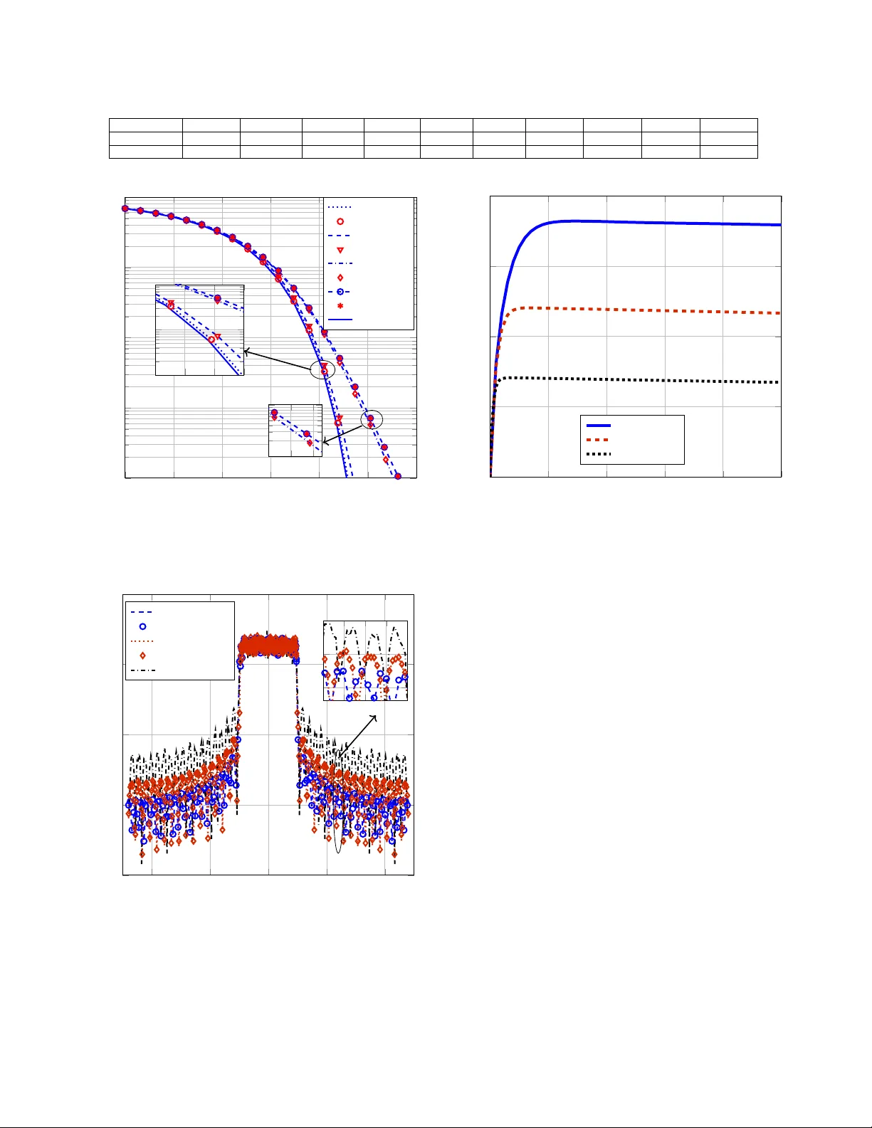
1 Analysis and Rate Optimization of GFDM-based Cogniti v e Radios A. Mohammadian, M. Baghani, C. T ellamb ura, F ellow , IEEE Abstract —Generalized frequency di vision multiplexing (GFDM) is suitable for cogniti ve radio (CR) networks due to its low out-of-band (OOB) emission and high spectral efficiency . In this paper , we thus consider the use of GFDM to allow an unlicensed secondary user (SU) to access a spectrum hole. Howev er , in an extremely congested spectrum scenario, both active incumbent primary users (PUs) on the left and right channels of the spectrum hole will experience OOB interference. While constraining this interference, we thus in vestigate the problem of power allocation to the SU transmit subcarriers in order to maximize the overall data rate where the SU recei ver is employing Matched filter (MF) and zero-f orcing (ZF) structures. The power allocation pr oblem is thus solved as a classic con vex optimization problem. Finally , total transmission rate of GFDM is compared with that of orthogonal frequency division multiplexing (OFDM). For instance, when right and left interference temperature should be below 10 dBm, the capacity gain of GFDM over OFDM is 400 % . Index T erms —CR network, GFDM, Signal-to-interfer ence- plus-noise ratio, Adjacent channel interference, Rate optimization problem I . I N T R O D U C T I O N T HE dev elopment of fifth generation (5G) wireless net- works faces the challenge of congested and limited wireless spectral resources [1]. The main reasons for that are the massiv e growth of wireless data traf fic and the assignment of almost all spectrum bands belo w 6-GHz bands to existing wireless and cellular applications. Howe ver , primarily due to usage patterns, many spectrum bands temporarily become spectrum holes. A spectrum hole is a free frequency band in a certain location in which the licensed (primary) users are not transmitting temporarily . Such spectrum holes can be accessed by unlicensed users or secondary users (SUs) under the interweav e cognitive radio (CR) paradigm. In 5G, the physical layer (PHY) maybe based on orthogonal frequency division multiplexing (OFDM) or Generalized fre- quency devision multiplexing (GFDM) [2]. Although OFDM is robust against frequency selectiv e fading, its high out-of- band (OOB) interference may render it unsuitable for CR networks [3]-[6]. GFDM has thus been proposed [7], [8]. GFDM uses multiple symbols per subcarrier and shapes each subcarrier by a circularly-shifted prototype filter . The spectral efficienc y of GFDM is higher than that of OFDM because the former uses only single cyclic prefix (CP) for an entire block. As well, GFDM can reduce the latency of PHY layer [9], the main requirement of T actile Internet [10]. In addition, due to the shaping of each subcarrier indi vidually , the OOB emission of GFDM is low [11] and can be further reduced by better design of filtering [12]. Multicarrier signaling methods are especially vulnerable against the carrier frequenc y of fset (CFOs) between transmitter and recei ver , which arise due to Doppler effects, thermal ef fects, aging and others. In OFDM, a CFO kills the perfect orthogonality among all the subcarriers, resulting in the lowering of the signal to interference ratio (SIR). In contrast, in GFDM, a receiv er filter can improve robustness against CFOs [13], which maximizes the SIR. Thus, these adv antages ensure that GFDM is an attracti ve modulation method for 5G and CR networks [14], [15]. Howe ver , GFDM incurs additional implementation complexity which has been improv ed in [16]–[19]. Due to these advantages, especially the lo w OOB emissions, we consider the use of GFDM for unlicensed CR users in this paper . Unlicensed SUs may access the primary user (PU) spectrum in two different modes. First, in underlay mode, they access simultaneously with acti ve PU transmissions, but ensure that the resulting interference on PU nodes is less than a specified interference threshold. Thus, in this mode, dynamic interfer- ence management is the key – which can be achieved by sev eral techniques such as secondary transmit power control, guard regions and/or proactiv e interference cancellation. Un- fortunately , these techniques will constrain the achiev able SU rates. Moreov er , the burden of implementing such techniques falls on the secondary network. Second, in the interweave mode, the SUs access spectrum holes only [20]. And that is the scenario in vestigated in this paper . The challenge, howe ver , is the accurate and dynamic sensing of spectrum holes. T wo com- mon sensing methods are energy detection and cyclostationary detection. [21] rev eals GFDM has a better complementary receiv er operating characteristic (R OC) compared to OFDM based on energy detection method. In addition, Reference [22] shows signal detection improves with GFDM due to its cyclostationary autocorrelation properties compared to OFDM. In light of these advantages, GFDM appears as a suitable candidate for interwea ve CR networks. Although optimal power allocation improv es the SU net- work performance, the interference on incumbent PUs network must be belo w guaranteed interference thresholds. Specifically , in this paper, we consider the problem of the OOB emission of SU over spectrum hole affecting the activ e PUs in the adjacent channels. The resource allocation for OFDM CR is first con- sidered in [23], and other heuristic and fast resource allocation methods are proposed in [24], [25]. Howe ver , GFDM uses non-orthogonality of subcarriers whereas OFDM uses orthog- onal ones. Thus the power allocation problem is completely different between GFDM and OFDM. Thus, the signal-to- interference-plus-noise ratio (SINR) is more complicated. In [26], GFDM power allocation in underlay cognitive radio is 2 S pe ctr um ho le SU PU PU h ℎ 𝑟 ℎ 𝑙 𝑓 S U tr an sm it t er S U r ec eiv er PU r ec ei v er D ir ec t ch an ne l A dj ac en t ch an ne l in t er f er en ce Fig. 1: The cognitive radio model. solved via genetic algorithms. In [27], CR resource allocation is done by particle swarm optimization (PSO). Ho we ver , although the optimization problem is not con vex due to the in- terference on subcarriers, the dual Lagrange multiplier method is used as analytical solution in [27]. Also, the metaheuristic approaches for non-con ve x optimization problems, e.g. PSO, do not guarantee to reach to the global optimum due to the lack of an y theoretical basis. T o the best of our kno wledge, no analytical resource allocation strategies to increase the spectral efficienc y of GFDM SUs for different recei ver structures have been published before. In Fig. 1, we consider an SU link consisting of an SU transmitter and SU receiv er operating ov er a spectrum hole in which PUs are not present temporarily . Also, two PUs are active in left and right channels of the spectrum hole. Furthermore, the interference lev els from PUs to the SU link are assumed to be negligible. W e consider GFDM system for different cases: 1) uniform and non-uniform po wer allocation to subcarriers, 2) different number of subsymbols and 3) two common MF and ZF receivers. Moreover , a frequency selectiv e slow fading channel is considered. W e assume that channel state information (CSI) of all the links (e.g., SU transmitter to receiver and SU transmitter to PU receiv ers) is av ailable at the SU transmitter . It can estimate the CSI of SU-SU links by using any classic channel training, esti- mation, and feedback mechanisms. It can estimate the CSI of SU-PU links by utilizing beacon signals transmitted by PUs and by e xploiting channel reciprocity . In this paper , we in vestigate the problem of maximizing the SU rate under the constraints of maximum tolerable interference po wer on PU bands and maximum transmit power . This problem is solved for the aforementioned scenarios, and GFDM is compared with OFDM to determine the relativ e advantages of GFDM for CR networks. In detail, the contributions of this paper are follows. • For the SU link, we consider two different standard receiv er techniques; namely matched filter (MF) and zero forcing (ZF). W e deri ve their SINR and SIR as function of subcarrier po wer allocations. Moreov er , the accuracy of the deri ved formulas are verified by simulations. • Adjacent channel interference (A CI) of the SU on the activ e users on right and left channels of the utilized spectrum hole are deriv ed and incorporated to define the constraints of rate optimization problem. For this purpose we deriv e the power spectral density (PSD) of GFDM non-equal subcarrier po wer allocations. • The maximization problems for the total rate of SU with GFDM in a CR network are defined. After con ve xifying the optimization problems by adding an interference threshold, an analytical solution to the optimal subcarrier power allocations is proposed by utilizing the Lagrange method. • The impact of the number of subsymbols, a critical parameter in GFDM, on the symbol error rate (SER) performance and OOB emission of MF and ZF receivers is inv estigated, and their sum rate performances are considered. • Finally , we compare the spectral efficiencies of GFDM and OFDM. For dif ferent power allocations, we show that GFDM achiev es higher ef ficiency than OFDM due to its lower OOB emission. Note that the proposed algorithm provides high SU transmission rate while satisfying the tolerable interference temperature constraints on PUs spectrum. These advantages are suitable for opportunistic spectrum access in practical applications, e.g. CR TV white space (TVWS) transmission. The rest of this paper is org anized as follo ws: the system model is presented in Section II. The SINR and signal-to-noise ratio (SNR) of recei ved symbols in MF and ZF recei vers and their SER are deri ved in Section III. W e deri ve the power spectral density (PSD) of GFDM signal for non-identical power scaling for subcarriers and obtain the A CI on the right and left channels in Section IV. The rate optimization problems are defined and solved in Section V. Simulation and numerical results in Section VI verify the accuracy of the analytical expressions and confirm the benefits of the optimization results. Finally , concluding remarks are provided in Section VII. I I . S Y S T E M M O D E L In our system model (Fig. 1), the SU uses GFDM and the SU transmitter-recei ver channel is denoted by h . W e assume the PUs are acti ve in the two adjacent channels of the spectrum hole which is used by the SU. The gains of these two channels are denoted by h r and h l . These gains will determine the amount of A CI falls on the PUs. In GFDM, let ~ s = [ s (0) , ....., s ( M K − 1)] T be M K × 1 complex data v ector with independent and identically dis- tributed (i.i.d) entries, which are chosen from 2 µ − QAM complex constellation where µ is the modulation order . GFDM contains K subcarriers which transmit data of M time- slots. The input data vector is assigned to M time-slots according to ~ s = h [ s 0 ] T , [ s 1 ] T , [ s 2 ] T , ......, [ s M − 1 ] T i T where [ s m ] = [ s m, 0 , s m, 1 , s m, 2 , ......, s m,K − 1 ] T . Thus, s m,k is the transmitted data symbol in k -th subcarrier of m -th time-slot. 3 The GFDM signal per frame may be written as x [ n ] = K − 1 X k =0 M − 1 X m =0 √ α k s m,k g T x m [ n ] e j 2 π ( k − K − 1 2 ) K n (1) where α k is po wer allocated to the k -th subcarrier, g T x m [ n ] = g T x [ n − mK ] M K is circularly shifted version of the transmit- ted prototype filter g T x [ n ] and 0 ≤ n ≤ M K − 1 . Furthermore, by representing output samples of GFDM modulator as a M K × 1 vector ~ x = [ x [0] , x [1] , x [2] , ....., x [ M K − 1]] T , one block of GFDM signal is given by ~ x = A ~ s , where A is a M K × M K modulation matrix given by [ A ] n,mM + k = g T x m [ n ] e j 2 πn ( k − K − 1 2 ) K . The signal x [ n ] is sent over the wireless channel. Given sufficiently long CP , perfect synchronization and knowledge of the channel impulse response, the receiv er can remove the CP . As a result, circular con volution with channel impulse response can be considered as ~ y = ~ h ⊗ ~ x + ~ w , where ⊗ denotes circular con volution and w is additiv e white Gaussian noise (A WGN). Then, frequency domain equalization (FDE) is used and The equalized signal is ~ u = ~ x + ~ w eq , where ~ w eq = IFFT n ~ W ~ H o , ~ W and ~ H are the noise vector and the channel response in frequency domain, respectively . The resulted vector goes through GFDM demodulator and vector of the estimated symbols is calculated by ~ b s = B ~ u , where B is recei ver matrix. The receiv er matrix for MF and ZF linear GFDM recei vers are equal to A H and A − 1 , respecti vely . In the MF recei ver B is selected to maximizing the signal-to-noise ratio (SNR) for each symbol without considering interference. In GFDM, howe ver , subcarriers and subsymbols are not mutually or- thogonal. Thus, the inter-subcarrier interference will limit the performance of the MF receiver . T o eliminate it, the linear ZF receiv er can be used. Howe ver , the ZF receiv er has the drawback of enhancing the additiv e noise. W ith either of these recei vers, each estimated symbol at a giv en subcarrier and time-slot can be written as [17] b s m 0 ,k 0 = r m 0 ,k 0 + w eq ,m 0 ,k 0 (2) where w eq ,m 0 ,k 0 is the equiv alent noise and r m 0 ,k 0 is equal to r m 0 ,k 0 = 1 √ α k 0 M K − 1 X n =0 x [ n ] g ∗ Rx m 0 e − j 2 π ( k 0 − K − 1 2 ) K n (3) where g Rx [ n ] is the recei ve filter impulse response, g Rx m [ n ] = g Rx [ n − mK ] M K is circularly shifted version of that and ( . ) ∗ denotes the conjugate operator . I I I . R E C E I V E D S I N R D E R I V AT I O N S In this section, we derived the SINR for the MF and ZF receiv ers. A. MF r eceiver As mentioned before, the MF receiv er suf fers from self- generated interference. Nevertheless, SNR per subcarrier in this receiv er is maximized without considering this interfer- ence. By using (1), (2), (3) and substituting m = m 0 and k = k 0 , the output of this receiv er (2) can be rewritten as b s m 0 ,k 0 = s m 0 ,k 0 + n m 0 ,k 0 + w M F eq ,m 0 ,k 0 (4) where n m 0 ,k 0 = r m 0 ,k 0 − s m 0 ,k 0 is interference noise. T o deriv e SINR, the variance of each term is needed. First, v ariance of interference noise is derived as (see Appendix A). σ 2 n m 0 ,k 0 = E [ n m 0 ,k 0 n ∗ m 0 ,k 0 ] = 1 α k 0 K − 1 X k =0 α k f m 0 ,k 0 ( k ) − p s (5) where E [ . ] is the ensemble average operator and f m 0 ,k 0 ( k ) = M − 1 X m =0 M K − 1 X n 1 =0 M K − 1 X n 2 =0 α k p s g Rx m [ n 1 ] × g ∗ Rx m [ n 2 ] g ∗ Rx m 0 [ n 1 ] g Rx m 0 [ n 2 ] e j 2 π ( k − k 0 ) K ( n 1 − n 2 ) . (6) Second, the variance of equiv alent noise is calculated as [8] σ 2 w M F eq,m 0 ,k 0 = N 0 M K α k 0 M K − 1 X p =0 G M F m 0 ,k 0 [ − p ] H [ p ] 2 (7) where G M F m 0 ,k 0 [ p ] is frequency response of g ∗ Rx − M F m 0 [ n ] e − j 2 π ( k 0 − K − 1 2 ) K n , H [ p ] is channel frequency response and N 0 is noise power density . Due to (5) and (7), the SINR experienced by SU receiv er for MF at k -th subcarrier and m -th time-slot after the frequency selective A WGN channel can be expressed as Γ M F m 0 ,k 0 = R T p s σ 2 n m 0 ,k 0 + σ 2 w M F eq,m 0 ,k 0 = R T p s α k 0 K − 1 P k =0 α k f m 0 ,k 0 ( k ) − p s α k 0 + C M F m 0 ,k 0 (8) where C M F m 0 ,k 0 = α k 0 σ 2 w M F eq,m 0 ,k 0 , R T = M K M K + N C P and p s = E { s m 0 ,k 0 s ∗ m 0 ,k 0 } is average power of data symbols which for 2 µ − QAM modulation is equal to p s = 2(2 µ − 1) 3 . Furthermore, SER can be calculated for a GFDM system ov er frequency se- lectiv e channel with MF receiver by summation of probability of symbols decoded being in error for 2 µ − QAM as [8] P M F s =2 µ − 1 µM K M − 1 X m =0 K − 1 X k =0 erfc s 3Γ M F m 0 ,k 0 2(2 µ − 1) − 1 M K µ − 1 µ 2 M − 1 X m =0 K − 1 X k =0 erfc 2 s 3Γ M F m 0 ,k 0 2(2 µ − 1) . (9) where erfc( x ) is the complementary error function. The SER is an important parameter of quality of service (QoS) and (9) provides the means to test the accuracy of (8). 4 B. ZF receiver Unlike MF , ZF eliminates self-generated interference, but enhances additiv e noise. By considering (2), ZF estimated data of m -th time-slot in k -th subcarrier can be derived as b s m 0 ,k 0 = s m 0 ,k 0 + w Z F eq ,m 0 ,k 0 . (10) Due to (7), the received SNR at k -th subcarrier and m -th time- slot giv en the frequency selective and A WGN channel may be expressed as Γ Z F m 0 ,k 0 = R T p s σ 2 w Z F eq,m 0 ,k 0 = R T p s α k 0 C Z F m 0 ,k 0 . (11) Moreov er , SER of GFDM with ZF recei ver may be giv en by [8] P Z F s =2 µ − 1 µM K M − 1 X m =0 K − 1 X k =0 erfc s 3Γ Z F m 0 ,k 0 2(2 µ − 1) − 1 M K µ − 1 µ 2 M − 1 X m =0 K − 1 X k =0 erfc 2 s 3Γ Z F m 0 ,k 0 2(2 µ − 1) . (12) Note that variance of equiv alent noise is derived based on receiv er filter which is different for MF and ZF . I V . A D JAC E N T C H A N N E L I N T E R F E R E N C E In our model, the PUs are active in right and left adjacent channels of the spectrum hole. Thus, they will experience destructiv e interference because of the OOB emissions of the SU. T o study this ef fect, we assume frequency selective slow fading channels for PUs. Howe ver , with a sufficient cyclic prefix, the frequenc y selecti ve channel is equiv alent to multiple flat fading channels in frequency domain. For small frequency bin, the channel frequency response is constant across each frequency bin which are denoted by H r ( d ) and H l ( d ) for right and left neighboring channel responses in each frequency bin, respectiv ely , an e xample is sho wn in Fig. 2 for four subcarriers. The total A CI is calculated through summation of ACI on each frequency bin which is deriv ed by multiplying the adjacent channel power (ACP) in each frequency bin by channel gains. Therefore, total A CI at right neighboring channel may be expressed as P AC I = 2 K X d = K +1 P AC ( f d ) H r ( d − K ) (13) where P AC ( f d ) is A CP in frequency interval [ f d − 1 / (2 T s ) , f d + 1 / (2 T s )] where f d = K +2 d +1 2 T s is center of each frequency interval , T s is one time-slot duration and d is the index of frequency bin. T o find A CP in each frequency bin, the PSD of signal is deriv ed as (see Appendix B) S xx ( f ) = p s M T s K − 1 X k =0 α k S GG ( f − ( k − K − 1 2 ) T s ) (14) -3 -2 -1 0 1 2 3 Freq (MHz) -30 -25 -20 -15 -10 -5 PSD[dB] Left channel gains Right channel gains Spectrum of GFDM Fig. 2: PSD of GFDM and left and right channel gains for four subcarriers. where S GG ( f ) = M − 1 P m =0 | G T x m ( f ) | 2 and G T x m ( f ) is frequency response of each filter . According to (13) and (14), ACI in right adjacent channel can be derived as P r = K − 1 X k =0 α k T r ( k ) (15) where T r ( k ) = p s M T s 2 K X d = K +1 H r ( d − K ) f d +1 / (2 T s ) Z f d − 1 / (2 T s ) S GG ( f − ( k − K − 1 2 ) T s d f . (16) Similarly , ACI in left adjacent channel is calculated by P l = K − 1 X k =0 α k T l ( k ) (17) where T l ( k ) = p s M T s 2 K X d = K +1 H l ( d − K ) − f d +1 / (2 T s ) Z − f d − 1 / (2 T s ) S GG ( f − ( k − K − 1 2 ) T s d f . (18) These two derived powers must be belo w the acceptable interference thresholds of the left and right PU channels. This constraint will be incorporated into the rate optimization problem subsequently . V . P R O B L E M F O R M U L AT I O N W e next formulate and solve the maximization of the total transmission rate of the SU under interference constraint for both MF and ZF receivers. T echnically , we aim to find the optimal set of power allocations ( α 0 , α 1 , . . . , α K − 1 ) . 5 α k = M " K − 1 P k 0 =0 M − 1 P m 0 =0 γ m 0 + M k 0 ( f m 0 ,k 0 ( k ) − p s ) # + γ M K + γ M K +1 T r ( k ) + γ M K +2 T l ( k ) − Q n + C M F 0 ,k p s + (25) A. MF receiver W ith the MF receiver , according to (8),(15) and (17), the rate optimization problem can be formulated as max α k 0 ≤ k ≤ K − 1 K − 1 X k 0 =0 M − 1 X m 0 =0 log(1 + Γ M F m 0 ,k 0 ) (19) s.t. K − 1 X k =0 α k < α max (20) K − 1 X k =0 α k T r ( k ) < Q r (21) K − 1 X k =0 α k T l ( k ) < Q l (22) where Q r and Q l are the interference temperature limits for the right and left adjacent channels, respectiv ely . Furthermore, α max is the maximum total po wer that is divided between K subcarriers. Howe ver , because Γ MF m 0 ,k 0 is a rational expression of α k ’ s, the objectiv e function (19) is not con vex. T o ov ercome the non-con ve xity of objective function, we introduce an additional constraint to original problem [28] which is gi ven by K − 1 X k =0 α k f m 0 ,k 0 ( k ) − p s α k 0 < Q n ∀ m 0 , k 0 . (23) As shown in (4) , due to self-generated interference in MF receiv er, extracted symbols contain interference noise with which the total po wer of these terms hav e been calculated in (5). Thus, inequality constraint (23) can be interpreted as the sum of self-generated interference in each time-slot of each subcarrier being less than the self-interference noise threshold Q n . By setting this threshold Q n appropriately , we can improv e the system performance. The resulting conv ex optimization problem is solved by utilizing the method of Lagrange multipliers to encapsulate all the constraints: L ( α, γ ) = K − 1 X k 0 =0 M − 1 X m 0 =0 log(1 + p s α k 0 Q n + C M F m 0 ,k 0 ) + K − 1 X k 0 =0 M − 1 X m 0 =0 γ m 0 + M k 0 ( Q n − K − 1 X k =0 α k f m 0 ,k 0 ( k ) + p s α k 0 ) + γ M K ( α max − K − 1 X k =0 α k ) + γ M K +1 ( Q r − K − 1 X k =0 α k T r ( k )) + γ M K +2 ( Q l − K − 1 X k =0 α k T l ( k )) (24) where γ j , j = 0 , ..., M K + 2 , are Lagrange multipliers. Due to the standard con ve x form of this problem, the Karush- Kuhn-T ucker (KKT) conditions, which are the first order necessary and sufficient conditions for optimality , yield the optimal solution. Thus, the optimal power allocated to each subcarrier as a function of the Lagrange multipliers is obtained as (25), where [ x ] + = max(0 , x ) and k is the subcarrier index. From the Lagrangian duality , (24) should be minimized on Lagrangian multipliers. Thus, they can updated by using the sub-gradient method. The subgradient update equations are giv en by γ m 0 + M k 0 ( t + 1) = " γ m 0 + M k 0 ( t ) + ζ ( K − 1 X k =0 α k f m 0 ,k 0 ( k ) − p s − Q n ) # + γ M K ( t + 1) = " γ M K ( t ) + ζ ( K − 1 X k =0 α k − α max ) # + γ M K +1 ( t + 1) = " γ M K +1 ( t ) + ζ ( K − 1 X k =0 α k T r ( k ) − Q r ) # + γ M K +2 ( t + 1) = " γ M K +2 ( t ) + ζ ( K − 1 X k =0 α k T l ( k ) − Q l ) # + (26) where ζ denotes the positiv e step size. Thus, the entire iterativ e process for solving this rate optimization problem is given in Algorithm. 1. Due to the conv exity of our problem, the duality gap is zero and the proposed algorithm is optimal. W e should note that if equal power for subcarriers are considered, we can set α k = α . Thus, the optimum amount of the power which satisfies all constraints could be deriv ed as α opt = min Q n K − 1 P k =0 f m 0 ,k 0 ( k ) − p s , α max K , Q r K − 1 P k =0 T r ( k ) , Q l K − 1 P k =0 T l ( k ) . (27) This solution is the just the power level that will not violate all the constraints. B. ZF receiver Like the MF receiv er, the ZF rate maximization problem is formulated as max α k 0 ≤ k ≤ K − 1 K − 1 X k 0 =0 M − 1 X m 0 =0 log(1 + Γ Z F m 0 ,k 0 ) (28) s.t. (20) , (21) , (22) . 6 Algorithm 1 Rate optimization 1: Initialize the maximum number of iteration I max and con vergence condition ε γ 2: set t ← 1 3: do while K − 1 P i =1 | α k ( t ) − α k ( t − 1) | > ε γ and t < I max 4: t ← t + 1 5: Obtain α k by using deri ved formula 6: Update the Lagrange multipliers 7: end do 8: retur n Since this problem is con ve x, the Lagrangian for this opti- mization problem is obtained as L ( α, γ ) = K − 1 X k 0 =0 M − 1 X m 0 =0 log(1 + p s α k 0 C Z F m 0 ,k 0 ) + γ 0 0 ( α max − K − 1 X k =0 α k ) + γ 0 1 ( Q r − K − 1 X k =0 α k T r ( k )) + γ 0 2 ( Q l − K − 1 X k =0 α k T l ( k )) (29) where γ 0 i , i = 0 , 1 , 2 , are Lagrangian multipliers. Based on KKT conditions, the optimal power allocated to each subcarrier is calculated as α k = " M γ 0 0 + γ 0 1 T r ( k ) + γ 0 2 T l ( k ) − C Z F 0 ,k p s # + . (30) The subgradient equations for updating the lagrangian co- efficients in each iteration can be derived as γ 0 0 ( t + 1) = " γ 0 0 ( t ) + ζ ( K − 1 X k =0 α k − α max ) # + γ 0 1 ( t + 1) = " γ 0 1 ( t ) + ζ ( K − 1 X k =0 α k T r ( k ) − Q r ) # + γ 0 2 ( t + 1) = " γ 0 2 ( t ) + ζ ( K − 1 X k =0 α k T l ( k ) − Q l ) # + . (31) As before, the optimization problem (28) is solved with Algorithm 1. Same as previous section, the optimum problem for uniform po wer allocation is derived as α opt = min α max K , Q r K − 1 P k =0 T r ( k ) , Q l K − 1 P k =0 T l ( k ) . (32) Note that all the derived analytical formulas are general and hold for arbitrary signaling alphabet, numbers of subcarriers and subsymbols and any type of prototype filter . Indeed, in all cases, our proposed algorithms for MF and ZF can provide optimal po wer allocation to maximize the rate of SU. T ABLE I: GFDM, channel and system parameters parameter V alue Mapping 16 − QAM Filter type Raised − cosine Roll-off factor 0 . 15 Symbol duration ( T s ) 33.3 µs Number of subcarriers ( K ) 64 Number of sub symbols ( M ) 5,15 Subcarrier spacing ( 1 T s ) 30 K H z Signal Bandwidth ( K T s ) 1.92 M H z CP length ( N cp ) 10 Channel length ( N ch ) 10 V ariance of each tap (10 − i N ch − 1 ) i =0 ,...,N ch − 1 Number of OFDM subcarriers 64 V I . S I M U L A T I O N A N D N U M E R I C A L R E S U LT S In this section, the deri ved SERs and PSD are validated with simulations and optimization results are presented. The parameters of GFDM and channel are shown in T able I. The A veraged periodogram algorithm with 50 % ov erlap and Han- ning window is used to estimate the PSD and length of FFT (fast F ourier transform) is set to 65536. Monte carlo simulation uses 1000 GFDM symbols per run. Moreover , the value of threshold is equal to 0.0001 and α max = 55 dBm. In Section VI-A, the SER of (9) and (12) are verified by simulations. The accuracy of deriv ed PSD for GFDM modulated signal (14) is validated by simulation. In Section VI-B, the performance of proposed Algorithm 1 for both GFDM and OFDM with uniform and non-uniform power allocation to subcarriers is ev aluated. A. V erification of derived r esults In Fig. 3, the SER of GFDM with MF or ZF recei vers are compared with that of OFDM. E s is av erage transmit power which for GFDM is equal to E s = p s K K − 1 P k =0 α k and N 0 is normalized to one. On the one hand, as can be seen, the simulation results verify the analytical deriv ation of SER for MF and ZF receiv ers in (9) and (12), respectively . Therefore, we can conclude that the deriv ed formulas for SINR of MF (8) and SNR of ZF (11) are accurate. Also, with GFDM, ZF outperform MF , which has performance approximately near that of OFDM. On the other hand, more subsymbols degrade the SER performance of both MF and ZF receivers. This degradation is due to noise enhancement in both receivers when the number of subsymbols is increased. Note that α max has been chosen according to Fig. 3. Fig. 4 shows the PSD of GFDM with different numbers of subsymbols is compared with that of OFDM. A set of random power allocations for subcarriers is generated and has been utilized for all three scenarios. As can be seen, the simulation results verify the deri ved PSD (14). Moreover , the increased number of subsymbols decreases the PSD rapidly on adjacent channels. Indeed, OOB emission decreases by increasing the number of GFDM subsymbols. This result is in contrast with effect of increasing number of subsymbols on SER performance. Thus, although more subsymbols decreases 7 T ABLE II: Optimum v alues of Q n extracted for different interference power constraints by considering two dif ferent number of subsymbols . Subsymbols -20 dBm -15 dBm -10 dBm -5 dBm 0 dBm 5 dBm 10 dBm 15 dBm 20 dBm 25 dBm M = 5 0.0022 0.0044 0.0155 0.03 0.07 0.15 0.34 0.7 1.435 1.435 M = 15 0.0133 0.0233 0.04 0.091 0.1933 0.47 1.02 2.11 2.11 2.11 0 5 10 15 20 25 30 10 − 4 10 − 3 10 − 2 10 − 1 10 0 E s / N 0 (dB) SER 20 21 22 23 10 − 4 10 − 3 10 − 2 25 26 27 10 − 4 10 − 3 ZF-M=5(S) ZF-M=5(T) ZF-M=15(S) ZF-M=15(T) MF-M=5(S) MF-M=5(T) MF-M=15(S) MF-M=15(T) OFDM Fig. 3: SER of GFDM (with MF and ZF receivers) and of OFDM. Legend: S=simulation and T=theory . − 4 − 2 0 2 4 − 20 0 20 40 60 Freq (MHz) PSD (dBm) GFDM-M=15(S) GFDM-M=15(T) GFDM-M=5(S) GFDM-M=5(T) OFDM 2 2 . 2 2 . 4 2 . 6 2 . 8 0 10 20 Fig. 4: PSDs of GFDM and OFDM signals. the OOB emission, the SER also degrades. The SER is af fected due to in-band noise which influences the transmission rate while OOB emission indicates the out-of-band noise which plays a main role in the CR constraints. In the next section, we in vestigate the trade-off between these two effects of 0 0 . 1 0 . 2 0 . 3 0 . 4 0 . 5 0 1 2 3 4 Q n Capacity(bit/Hz) Q r =Q l =5 dBm Q r =Q l =0 dBm Q r =Q l =-5 dBm Fig. 5: Capacity of the GFDM with MF receiver versus Q n for three constant interference power constraints. increasing the number of subsymbols. B. Optimization Results In this part, we ev aluate the performance of GFDM and OFDM systems subject to the CR constraints. As the first step, we in vestigate the effect of the self-interference threshold Q n on the transmission rate to find the best value of Q n . Since this value helps us to conv ert the optimization problem into con ve x form, determining the right value so important. After that, the rate optimization problem is solved by using the Lagrangian method. Finally , the simulation results are presented and the performance of the proposed algorithm is compared between GFDM system with ZF and MF recei vers and OFDM system and the influence of number of subsymbols is considered as well. As mentioned, the amount of self-interference, considered as an extra constraint and transformed the problem into conv ex optimization problem, has an impact on the transmission rate of the SU. T o ev aluate this effect and find the optimal value, we solve the optimization problem for the fixed value of interference po wer constraint. W e sweep Q n ov er a range to find the optimum one which maximizes the total transmission rate. Fig. 5 shows the transmission rate versus value of Q n for three amounts Q r and Q l (5 dBm, 0 dBm and -5 dBm) where the number of subcarriers and subsymbols are set to 64 and 5, respectiv ely . As expected, this power allocation problem 8 − 20 − 10 0 10 20 30 − 0 . 5 0 0 . 5 1 1 . 5 2 2 . 5 Q r = Q l (dBm) Capacity (bit/s/Hz) M=5, Non-uniform M=5, Uniform M=15, Non-uniform M=15, Uniform OFDM, Non-uniform OFDM, Uniform (a) M F − GF D M − 20 − 10 0 10 20 30 − 0 . 5 0 0 . 5 1 1 . 5 2 2 . 5 Q r = Q l (dBm) Capacity(bit/s/Hz) M=5, Non-uniform M=5, Uniform M=15, Non-uniform M=15, Uniform OFDM, Non-uniform OFDM, Uniform 25 30 35 1 . 8 1 . 9 2 2 . 1 (b) Z F − GF D M Fig. 6: T otal sum rate of the SU of GFDM with MF and ZF receiv ers in compare with OFDM. has an optimum value. By utilizing the same procedure, for two number of subsymbols ( M = 5 and M = 15 ) with dif ferent v alues of interference po wer constraint, the optimization problem is solved and the optimum v alues of Q n are giv en in T ableII. In the following, these fixed value of Q n is chosen for the rate optimization problem. Fig. 6 represents the results of the rate optimization prob- lems for GFDM and OFDM systems. The achiev able trans- mission rate for GFDM system with MF and ZF receivers are shown in Fig. 6a and Fig. 6b, respectiv ely , in which the results contain uniform and non-uniform power allocations to subcarriers. As expected, in both cases of MF and ZF , non- uniform po wer allocation has better performance in compare with allocating equal power to all subcarriers. On the one hand, in Fig. 6a, when the interference power constraint is not dominant and the OOB emission does not cause any problem in CR e.g. Q r = Q l = 30 dBm, due to the non orthogonality of GFDM and self-interference, OFDM system should achieves higher rate. Similarly , although, the SER performance of ZF receiv er is lower than OFDM, the transmission rate of that is higher than OFDM due to the inserting one CP to each GFDM frame including symbol of M time-slots. Now when the amount of interference power constraints decrease and become dominant, where is sufficient for the CR system, the GFDM system in both case of MF and ZF receiv ers achieves higher rates which is caused by lo wer OOB radiation of GFDM system in compare with OFDM system. On the other hand, we in vestigate the impact of number of subsymbols for GFDM system with both MF and ZF receiv ers. we can conclude that in low amount of interference power constraint, GFDM system with both type of receivers transmits higher rate in case of M = 15 than M = 5 due to the lower OOB emission and is declared in Fig. 4. But, since the SER performance of GFDM system is decreased by increasing the number subsymbols, when the interference power constraint is not dominant, the achiev able rate in case of M = 5 is higher than M = 15 . Consequently , in the CR system, the GFDM system with MF and ZF receivers transmits higher rate in compare with OFDM system in both case of uniform and non-uniform po wer allocation to subcarriers. Also, increasing the number of subsymbols can help us to achieve higher rate. T o compare the performance of ZF and MF receivers, the total transmitted rates of GFDM system for M = 5 subsym- bols are illustrated in Fig. 7. When the interference power constraint is not dominant, because the SER performance ZF recei ver is better than that of MF receiv er , the former achiev es higher transmission rate. But, when the interference power constraint decreases, the rate of MF receiv er exceeds that of the ZF receiv er . This phenomena is caused by the decreasing amount of interference appearing in SINR (8) when the amount of powers allocated to subcarriers decrease. Since MF receiver maximizes the SNR without considering the interference, when the interference can be neglected, the MF receiver has the best performance. Consequently , when the interference power constraint is non-dominant, the system with ZF receiv er achiev es a higher rate. But, by decreasing the interference power constraint and eliminating the interference, the system with MF receiver achieves higher transmission rate than the one with ZF receiv er . Fig. 8 shows the total optimized transmit po wer versus the interference power constraint. GFDM with ZF and MF re- ceiv ers achieves higher transmit power than that with OFDM. The reason is that the interference po wer constraint becomes dominant in GFDM later than in OFDM, which is due to lower OOB emission of GFDM system. On the other hand, more subsymbols leads to decrease OOB emission. Thus, in case of M = 15 , higher power is transmitted in compare with M = 5 . All of these results confirm the previous results 9 − 20 − 10 0 10 20 30 0 0 . 5 1 1 . 5 2 Q r = Q l (dBm) Capacity(bit/s/Hz) ZF ,Non-uniform ZF , Uniform MF , Non-uniform MF , Uniform − 20 − 15 − 10 − 5 0 5 · 10 − 2 0 . 1 0 . 15 0 . 2 Fig. 7: T otal sum rate of GFDM with ZF and MF receivers for M = 5 . − 20 − 10 0 10 20 30 10 20 30 40 50 60 Q r = Q l (dBm) T otal allocated po wer (dBm) GFDM-ZF ,M=5 GFDM-ZF ,M=15 GFDM-MF ,M=5 GFDM-MF ,M=15 OFDM Fig. 8: T otal transmitted power versus different power inter- ference constraints. in which utilizing the GFDM system with higher number of subsymbols in lower interference power constraint can satisfy the CR system demand. Moreover , when the interference power constraint decreases, higher transmit power is achiev ed by the system with the MF receiv er in comparison with ZF receiv er . This observation also agrees with Fig. 7. Fig. 9 represents the average interference power based on po wer allocation results versus interference power which contains the GFDM and OFDM systems. Both MF and ZF receiv ers are considered for GFDM system. As expected, the av erage interference power is approaching to specific value − 20 − 10 0 10 20 30 − 20 − 10 0 10 20 30 40 Q r = Q l (dBm) Interference po wer (dBm) GFDM-ZF GFDM-MF OFDM Fig. 9: Interference power versus different values of Q r . of interference power constraint. This figure shows that the optimization realizes the interference lev el and not exceed the allowed value which is determined for interference po wer constraint. V I I . C O N C L U S I O N This paper evaluated the performance of a GFDM based CR network where unlicensed secondary users access the primary spectrum. Specifically , we considered a secondary user transmitting on a spectrum hole whose left and right adjacent bands are occupied by primary users. T o constrain the ACI on the left and right channels, we deriv ed the PSD of GFDM signal with the non-equal power subcarriers. T o determine the sum rate of the SU, we deriv ed the SINR and SNR for MF and ZF receiv ers, respectiv ely . The SER and GSD expressions were validated over by simulations over frequency selectiv e fading and A WGN channels. The simulation results also showed that the SER performance degrades and OOB leakage decreases when the number of subsymbols increases. W e also optimized the SU rate subject the ACI constraints on left and right channels and maximum total po wer . In MF case, by adding the new constraint on limitation of self- generated interference the problem was conv erted to con vex form. Also, the maximum self-generated interference limit of this constraint which maximizes the sum rate of the SU was extracted by simulation. The resuting rate optimization problems were solved by using the Lagrangian method. W e compared the total transmitted rate of the SU, utilizing GFDM with MF and ZF receivers, with OFDM for both uniform and non-uniform po wer allocations to subcarriers. The simulations sho w that the total rate of SU for our pro- posed po wer allocation algorithm is significantly higher than uniform power allocation in all cases and that GFDM achieves higher data throughput than OFDM in a CR network where the A CI constraints are dominant. In this case, MF recei ver 10 can achie ve more total rate compared with ZF receiver . But when the A CI constraints are not dominant, the ZF receiv es achiev es better SER and data rates in comparison with MF . In this case, OFDM performs roughly equal to ZF and better than MF . Consequently , GFDM based CR nodes with MF and ZF receiv ers achieve high data rates, which can be enhanced by increasing the number of subsymbols. In future works, other impairments which af fect the OOB emission of SU on spectrum of PUs like as RF impairments specially nonlinear power amplifier can be in vestigated. A P P E N D I X A Due to (3) and (4), variance of interference noise can be written by σ 2 n m 0 ,k 0 = E [( r m 0 ,k 0 − s m 0 ,k 0 )( r ∗ m 0 ,k 0 − s ∗ m 0 ,k 0 )] = E [ r m 0 ,k 0 r ∗ m 0 ,k 0 ] + E [ s m 0 ,k 0 s ∗ m 0 ,k 0 ] − 2 r eal ( E [ r m 0 ,k 0 s ∗ m 0 ,k 0 ]) (33) By considering normalized prototype pulse shape ( M K − 1 P n =0 | g T x [ n ] | 2 = 1 ), each part of (33) can be calculated as E [ r m 0 ,k 0 r ∗ m 0 ,k 0 ] = 1 α k 0 K − 1 X k =0 α k f m 0 ,k 0 ( k ) E [ s m 0 ,k 0 s ∗ m 0 ,k 0 ] = p s E [ r m 0 ,k 0 s ∗ m 0 ,k 0 ] = p s M K − 1 X n =0 | g m 0 [ n ] | 2 = p s (34) According to (33) and (34), (5) is deriv ed. A P P E N D I X B According to (1), the continuous form of GFDM signal by concatenating frames is expressed as x ( t ) = ∞ X υ = −∞ K − 1 X k =0 M − 1 X m =0 √ α k s m,k,υ g T x m ( t − υ T B ) e j 2 π ( k − K − 1 2 ) T s t (35) Where g T x m ( t ) is continuous form of g T x m [ n ] with the length of M T s and T B is block duration which is equal to M T s . T o calculate its PSD, autocorrelation of x ( t ) is deriv ed as R xx ( t, τ ) = p s ∞ X υ = −∞ K − 1 X k =0 M − 1 X m =0 α k g T x m ( t − υ T B ) g ∗ T x m ( t − τ − υ T B ) e j 2 π ( k − K − 1 2 ) T s τ (36) Since GFDM yields cyclostationary process, R xx ( t, τ ) = R xx ( t + M T s , τ ) , the average of R xx ( t, τ ) over one period is calculated as R xx ( τ ) = 1 M T s M T s Z 0 R xx ( t, τ ) dt = p s M T s ( M − 1 X m =0 g m ( τ ) ⊗ g m ( − τ )) K − 1 X k =0 α k e j 2 π ( k − K − 1 2 ) T s τ (37) By taking the Fourier transform of (37), (14) is derived. R E F E R E N C E S [1] J. Andrews, S. Buzzi, W . Choi, S. Hanly , A. Lozano, A. Soong, and J. Zhang, “What will 5 G be?, ” IEEE J. Sel. Ar eas Commun. , vol. 32, no. 6, pp. 1065–1082, June 2014. [2] G. W under , P . Jung, M. Kasparick, T . W ild, F . Schaich, Y . Chen, S. T . Brink, I. Gaspar, N. Michailow , A. Festag, L. Mendes, N. Cassiau, D. Ktenas, M. Dryjanski, S. Pietrzyk, B. Eged, P . V ago, and F . W ied- mann, “5 G N OW: Non-orthogonal, asynchronous wav eforms for future mobile applications, ” IEEE Commun. Mag. , vol. 52, no. 2, pp. 97–105, Feb . 2014. [3] S. Haykin, “Cognitive radio: brain-empowered wireless communica- tions, ” IEEE J. Sel. Ar eas Commun. , vol. 23, no. 2, pp. 201–220, Feb. 2005. [4] Y . C. Liang, K. C. Chen, G. Y . Li, and P . Mahonen, “Cognitive radio networking and communications: an overvie w , ” IEEE T rans. V eh. T echnol. , vol. 60, no. 7, pp. 3386–3407, Sept. 2011. [5] M. Mirahmadi, A. Al-Dweik, and A. Shami, “ BE R reduction of O FD M based broadband communication systems over multipath channels with impulsiv e noise, ” IEEE T rans. Commun. , v ol. 61, no. 11, pp. 4602–4615, Nov . 2013. [6] J. V an De Beek and F . Berggren, “Out-of-band power suppression in O F DM , ” IEEE Commun. Lett. , vol. 12, no. 9, pp. 609–611, Sept. 2008. [7] G. Fettweis, M. Krondorf, and S. Bittner , “G F D M - generalized frequency division multiplexing, ” in Pr oc. IEEE V eh. T echnol. Conf. (VTC Spring) , Apr. 2009, pp. 1–4. [8] N. Michailow , M. MatthÃl ’, I. S. Gaspar , A. N. Caldevilla, L. L. Mendes, A. Festag, and G. Fettweis, “Generalized frequency division multiplex- ing for 5th generation cellular networks, ” IEEE T rans. Commun. , vol. 62, no. 9, pp. 3045–3061, Sept. 2014. [9] I. Gaspar, L. Mendes, M. MatthÃl ’, N. Michailow , A. Festag, and G. Fettweis, “ L T E-compatible 5G P H Y based on generalized frequency division multiplexing, ” in Pr oc. ISWCS , Aug. 2014, pp. 209–213. [10] G. P . Fettweis, “The tactile internet: Applications and challenges, ” IEEE V eh. T echnol. Mag. , vol. 9, no. 1, pp. 64–70, March 2014. [11] M. MatthÃl ’, N. Michailow , I. Gaspar, and G. Fettweis, “Influence of pulse shaping on bit error rate performance and out of band radiation of generalized frequency division multiplexing, ” in Proc. IEEE ICC W orkshop , June 2014, pp. 43–48. [12] S. Han, Y . Sung, and Y . H. Lee, “Filter design for generalized frequency- division multiplexing, ” IEEE T rans. Signal Pr ocess. , vol. 65, no. 7, pp. 1644–1659, April 2017. [13] B. Lim and Y . C. Ko, “ S IR analysis of O FD M and G F DM waveforms with timing offset, C F O and phase noise, ” IEEE Tr ans. W ireless commun. , vol. PP , no. 99, pp. 1–1, 2017. [14] M. MatthÃl ’, L. L. Mendes, N. Michailow , D. Zhang, and G. Fettweis, “W idely linear estimation for space-time-coded G F D M in low-latency applications, ” IEEE T rans. Commun. , vol. 63, no. 11, pp. 4501–4509, Nov . 2015. [15] D. Zhang, A. Festag, and G. Fettweis, “Performance of generalized frequency division multiplexing based physical layer in vehicular com- munication, ” IEEE T rans. V eh. T echnol. , v ol. PP , no. 99, pp. 1–1, 2017. [16] N. Michailow , I. Gaspar, S. Krone, M. Lentmaier, and G. Fettweis, “Generalized frequency division multiplexing: Analysis of an alternative multi-carrier technique for next generation cellular systems, ” in Proc. 9th ISWCS , Aug. 2012, pp. 171–175. [17] A. Farhang, N. Marchetti, and L. E. Doyle, “Low-complexity modem design for G F D M, ” IEEE T rans. Signal Pr ocess. , vol. 64, no. 6, pp. 1507–1518, March 2016. [18] P . W ei, X. G. Xia, Y . Xiao, and S. Li, “Fast D G T-based receivers for G F DM in broadband channels, ” IEEE Tr ans. Commun. , vol. 64, no. 10, pp. 4331–4345, Oct. 2016. 11 [19] P . C. Chen, B. Su, and Y . Huang, “Matrix characterization for G F DM : Low complexity M M SE recei vers and optimal filters, ” IEEE T rans. Signal Process. , v ol. 65, no. 18, pp. 4940–4955, Sept. 2017. [20] A. Goldsmith, S. A. Jafar , I. Maric, and S. Srini vasa, “Breaking spectrum gridlock with cognitiv e radios: An information theoretic perspectiv e, ” Pr oc. IEEE , vol. 97, no. 5, pp. 894–914, May 2009. [21] R. Datta, N. Michailow , S. Krone, M. Lentmaier, and G. Fettweis, “Generalized frequency division multiplexing in cognitiv e radio, ” in 2012 Proceedings of the 20th European Signal Pr ocessing Conference (EUSIPCO) , Aug. 2012, pp. 2679–2683. [22] D. Panaitopol, R. Datta, and G. Fettweis, “Cyclostationary detection of cognitive radio systems using G F D M modulation, ” in 2012 IEEE W ireless Communications and Networking Conference (WCNC) , April 2012, pp. 930–934. [23] G. Bansal, M. J. Hossain, and V . K. Bhargav a, “Optimal and suboptimal power allocation schemes for O F DM -based cognitive radio systems, ” IEEE T rans. W ireless commun. , vol. 7, no. 11, pp. 4710–4718, No vember 2008. [24] Y . Zhang and C. Leung, “Resource allocation in an O F DM -based cognitiv e radio system, ” IEEE Tr ans. Commun. , vol. 57, no. 7, pp. 1928–1931, July 2009. [25] S. W ang, F . Huang, and Z. H. Zhou, “Fast power allocation algorithm for cognitive radio networks, ” IEEE Commun. Lett. , vol. 15, no. 8, pp. 845–847, August 2011. [26] Ahmed A Rosas, Mona Shokair , and Sami A El_dolil, “Proposed optimization technique for maximization of throughput under using different multicarrier systems in cogniti ve radio networks, ” EEECEGC , pp. 25–33, 2015. [27] A. E. Daw oud, A. A. Rosas, M. Shokair , M. Elkordy , and S. E. Halafa wy , “P S O-adaptive power allocation for multiuser G F D M-based cognitiv e radio networks, ” in 2016 International Conference on Selected T opics in Mobile Wir eless Networking (MoWNeT) , April 2016, pp. 1–8. [28] D. W . K. Ng, E. S. Lo, and R. Schober , “Energy-ef ficient resource allocation in O F DM A systems with large numbers of base station antennas, ” IEEE T rans. W ir eless commun. , vol. 11, no. 9, pp. 3292– 3304, Sept. 2012.
Original Paper
Loading high-quality paper...
Comments & Academic Discussion
Loading comments...
Leave a Comment