Iterative (Turbo) Multiuser Detectors For Impulse Radio Systems
In recent years, there has been a growing interest in multiple access communication systems that spread their transmitted energy over very large bandwidths. These systems, which are referred to as ultra wide-band (UWB) systems, have various advantage…
Authors: E. Fishler, S. Gezici, H. V. Poor
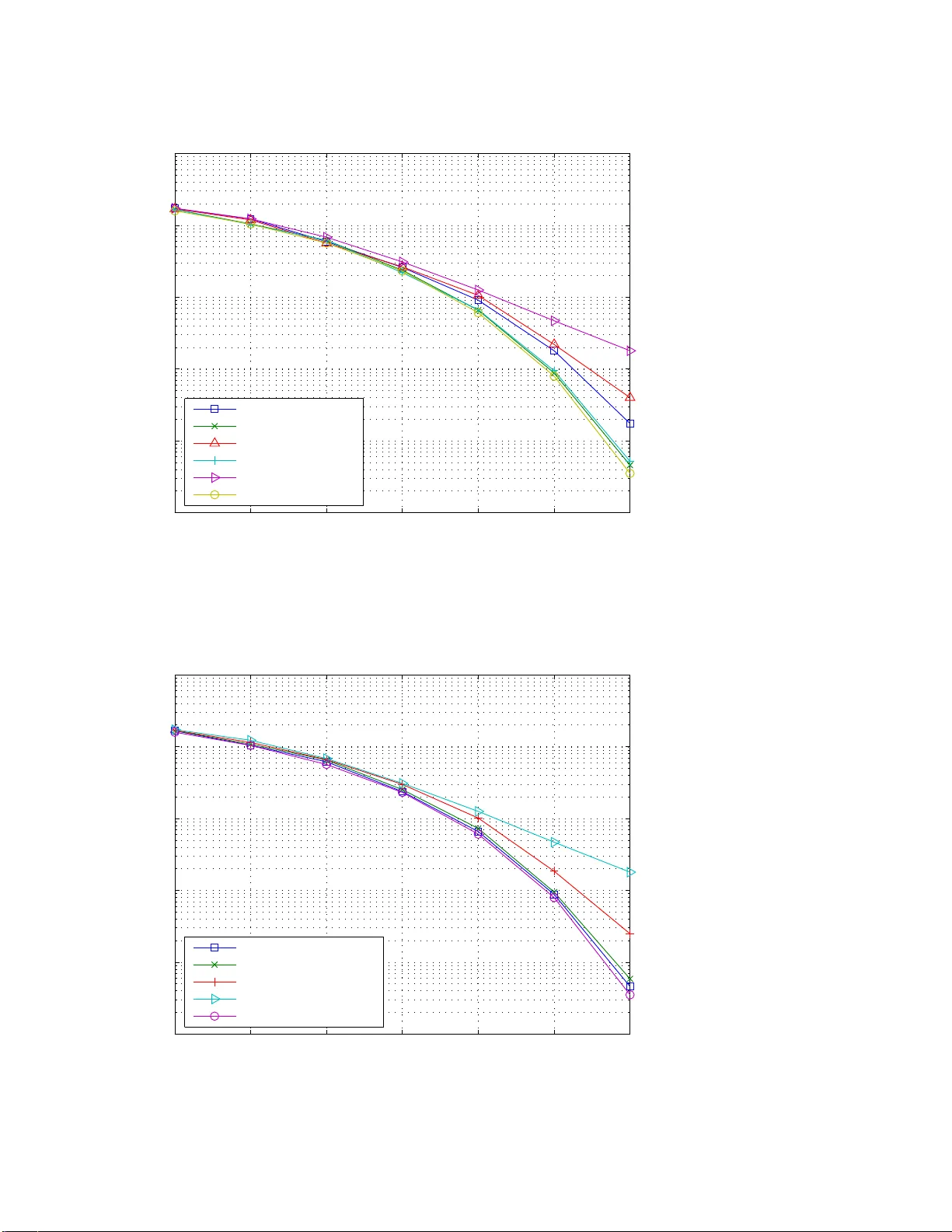
1 Iterat i v e (“T urbo”) Multiuser Detectors for Impulse Radio Systems Eran Fishler † , Sinan Gezici ∗ , and H. V incent Poor ‡ Abstract In recent years, there has been a g rowing interest in mu ltiple access com munication systems that spread their transmitted energy over very large b andwidths. Th ese systems, which are refer red to as ultra wide -band (UWB) systems, have various ad vantages over na rrow-band a nd conventional wide - band systems. The impor tance of multiu ser detection for achieving high data or low bit error rates in these systems has alr eady been estab lished in sev eral studies. Th is paper presents iterative (“tur bo”) multiuser detection fo r impulse radio (IR) UWB system s over multipath channels. While this appro ach is demonstra ted for UWB sign als, it can also be used in oth er systems th at use similar types of signalin g. When applied to the type of signals used by UWB systems, the com plexity of th e propo sed detector can be quite low . Also, two very low co mplexity im plementation s o f the iterative multiuser detection scheme are proposed based on Gaussian approx imation and soft interf erence ca ncellation. The p erforma nce of these detectors is assessed using simu lations that d emonstrate their fa vorable prop erties. Index T erms— Ultra wide-b and (UWB), impulse rad io (IR), itera ti ve multiuser detection, soft in ter- ference cancellation. This research was supported in part by the National Science Foundation under Grants ANI-03-38807 and CNS -06-2563 7. † Department of Computer Science, New Y ork University , NY 10012, USA, e-mai l: fishler@cs.nyu.edu ∗ Department of Electrical and Electronics Engineering, Bilkent Unive rsity , Bilkent, Anka ra 06800, T urke y , T el: +90 (312) 290-3139 , Fax: +90 (312) 266-4192, e-ma il: gezici@ee.bilken t.edu.tr ‡ Department of Electrical Engineering, Pr inceton Univ ersity , Princeton 08 544, USA, T el : (609) 258-2260 , Fax: (609) 258- 7305, e-mail: poor@princ eton.edu 2 I . I N T R O D U C T I O N In recent years, there has bee n a growing interest in ultra wide -band (UWB) systems, which resulted in the U.S. Fede ral Commu nications Commiss ion (FCC) re gulations that a llo w , u nder several restrictions, the widesprea d u se of s uch systems. The common definition of UWB sys tems, which was adopted by the FCC as we ll, s tates that a system is a UWB sy stem if b oth the abs olute a nd the fractional bandwidths are large. The abs olute bandwidth shou ld be a t least 0 . 5 GHz , while the fractional band width, w hich is the signal bandwidth divided b y the ca rrier frequency , is at least 20% [8]. UWB systems offer many advantages over narrow-band or con ventional wide -band syste ms. Amo ng these ad vantages are reduced fading mar gins, simple transceiver designs, lo w probability of detection, good anti-jam capa bilities, and accurate p ositioning (see , [5], [33], [14], and references therein). Th e advantages of UWB techno logy have ca used this tec hnology to be c onsidered for use as the physica l layer of several applica tions; for example, the IEEE 802 .15.4a wireless person al area network (WP AN) s tandard employs this tec hnology as one of the sign aling o ptions [37]. There are many signaling methods f or transmitting over UWB channe ls, and it is o bvious that, apart from enginee ring difficulties, one can use any existing sp read spectrum technique for transmitting over UWB channe ls [10], [32]. Howev er , the se dif ficulties might be quite significan t, preventing the actual use of con ventional spread-sp ectrum methods for trans mitting o ver UWB channels. Con sider , as an example, long-code direct-sequenc e cod e-di vision-multiple-access (DS-CDMA) systems. In these systems, implementing even the simplest de tector , namely the match ed filter detector , requires sampling of the received signa l at least at the chip rate, which under the cu rrent regulations might b e as large as 7 . 5 GHz. Such sampling rates a re dif ficult to achieve, a nd result in high power c onsumption. In o rder to overcome s ome of the dif ficulties asso ciated w ith UWB signaling, impulse r adio (IR) systems, an d es pecially time-hopping impulse radio (TH-IR) s ystems have bee n propo sed as the preferred modulation scheme for UWB sy stems [26]. In TH-IR systems, a train of sho rt pulses is transmitted, and the information is usually con veyed by either the polarity or loca tion of the tr ansmitted pulse s. In a ddition, in order to allow many users to share the sa me chann el, an add itional random (or pseu do-random) time s hift, known to the receiver , is a dded to the starting po int of each pulse. This way , probability of ca tastrophic collisions betwee n two use rs transmitting over the sa me chan nel at the same time is significantly redu ced [26]. 3 TH-IR modulation, e.g., binary phase s hift keyed (BPSK) TH-IR, to b e d iscussed in the following sections, has many advantages ov er con ventional modulation techniqu es. By using very short pulses, the transmitted en er gy is spread over a very large ban dwidth. In a ddition, by using pse udo-random time intervals be tween the transmitted p ulses and random pulse po larities, spectral lines a nd other spectral impairments a re av oided [13]. The implementation o f the receiver is usually easier for this techn ique becaus e the ch annel is excited for o nly a fraction of the total trans mission time. For example, the matche d filter detec tor needs to sample the filter matched to the rece i ved pulse on ly at time instants wh en puls es correspond ing to the user of interest arri ve at the receiver . Moreover , base -band pulse s a re typ ically used in UWB sys tems, sa ving the ne ed for complex frequency synchronization and tracking 1 . These ad vantages make TH-I R the preferr ed modulation scheme for transmitting o ver UWB channels i n vari ous applications. It should b e noted that IR-UWB ha s been chose n as one of the mod ulation formats for the IEEE 802.15. 4a WP AN standa rd. It ha s been obs erved [9], [21], [27], [35 ] that the transmitted a nd received signals of TH-IR s ystems can be desc ribed by the same models used for describing the transmitted and rec eiv ed s ignals of DS-CDMA systems. The main diff erence between class ical DS-CDMA s ignals and TH-IR s ignals is that TH-IR signals us e spread ing se quence s who se elements be long to the ternary a lphabet, i.e., {− 1 , 0 , +1 } , instead of the binary alpha bet, i.e., {− 1 , +1 } . This obs ervati on lead s to the immediate conclusion tha t ev ery multiuser de tector design ed for CDMA systems ca n be us ed in T H-IR systems as well. In particular , the optimal multiuser d etector can be e asily deduce d from [30], a nd the complexity of this detector for systems transmitting over multipath channe ls is known to be expon ential in the numbe r of acti ve users and the number of transmitted symbols falling within the de lay spread of the channe l. Linear receivers can b e des igned as well, resulting in multiuser detec tors having complexity that is polynomial in the number of acti ve users and the size of the observation windows used by the d etector [1], [22]. Although the classical algorithms for multiuser detection can be used in TH-IR s ystems, it is evident that lo w complexity multiuser detection algorithms for systems that use generalized s preading sequence s in general an d IR systems in pa rticular are required. T hese d etectors sho uld exploit the spec ial type of signa ls TH-IR sys tems trans mit in orde r to reduce the complexity of multiuser de tectors. In [9], an iterati ve multiuser de tector exploiting the s pecial structure of T H-IR signa ls is p roposed for ad diti ve white 1 It should be noted, howe ver , that if t he channel is com posed of a v ery l arge number of equipo wer paths, then the receiv er complex ity becomes v ery large due t o the need to sample al l of them in order to achiev e di versity combining. 4 Gaussian n oise (A WGN) chan nels. Iterati ve multiuser de tectors ca n b e des igned for TH-IR sys tems by considering the TH-IR signaling s tructure a s a concatena ted coding s ystem, whe re the inn er co de is the modulation and the outer code is the repetition code. Such a technique makes use of the similarit y be tween TH-IR signaling and bit interleaved coded mod ulation (BICM), where the inne r code is modula tion and the outer code is ch annel c oding [2], [6], [18], [36]. In this p aper , we first present a n extension o f the iterative mu ltiuser detector in [9] to more realistic multipath chan nels. Name ly , we propose an iterati ve detector structure tha t combines en er gy from a number of mu ltipath components. Althou gh o nly random TH -IR systems are described in the s equel, the multiuser detectors presented in this paper can be app lied to any o ther typ e of DS-CDMA syste m wh ose spreading seque nces con tain lar ge fraction of zeros. As such the contributi on of this pa per goes beyond the theory of UWB systems into the theory o f gene ral DS-CDMA systems. In a ddition, we propose two very low- complexity impleme ntations o f the iterati ve algo rithm, wh ich a re based on Ga ussian approximation for weak interferers, a nd on s oft interference c ancellation. The rest o f the pap er is organized as follo ws: In Se ction II, the s ignal model that is used throughou t the paper is de scribed. In Section III, an iterativ e multiuser detector , c alled the pulse-symbo l iterati ve detector , is prese nted for frequency-selec ti ve e n vironme nts. T hen, two novel and low- complexity imple- mentations of the p roposed recei ver are described in Section IV . In Sec tion V , simulations de monstrating the performance of the propose d detec tor whe n trans mitting over indoor UWB chann els are prese nted. Finally , a s ummary a nd some concluding remarks a re provided in Section VI. I I . D I S C R E T E - T I M E S I G N A L M O D E L TH-IR sy stems can be mod eled as DS-CDMA systems with generalized spreading seq uences that take values from the set {− 1 , 0 , +1 } [20], [12]. Th erefore, a K -use r DS-CDMA sync hronous s ystem transmitting over a frequency-selective ch annel is conside red in order to obtain the discrete-time signal model for a TH-IR sy stem 2 . It is assume d that each user transmits a p acket of P information sy mbols, and N denotes the processing gain of the sys tem. In addition, the channe l be tween ea ch u ser an d the recei ver is modeled to h av e L tap s, and h k = [ h k 1 · · · h k L ] denotes the dis crete time c hannel impulse resp onse between the k th transmitter and the receiver . Fina lly , s k ,i = [ s k i, 0 · · · s k i,N − 1 ] represents the spreading 2 The synchro nous assumption is made for notational con ven ience, but as we discuss in the sequel, the proposed algorithm works equally w ell in asynchrono us systems. 5 sequen ce that the k th user uses for spreading its i th information symb ol. No te that if s k ,i = s k ,j for every i and j , then the sy stems is a s hort-code sy stem; othe rwise it is a lon g-code s ystem. A c hip-sampled discrete-time model for the received signal can be described by the follo wing model: r = K X k =1 p E k H k S k b k + n , (1) where, for the k th use r ( k = 1 , . . . , K ): E k is the trans mitted energy per symbo l; H k is an ( N P + L − 1) × N P matrix, who se i th column is eq ual to [ 0 i − 1 , h k , 0 N P − i ] T and 0 l is the all zero row vector of length l ; S k is an N P × P spread ing matrix containing the P sprea ding sequenc es t hat the k th u ser uses for sp read- ing the transmitted s ymbols, S k = [ s k , 1 0 N ( P − 1) ] T , [ 0 N s k , 2 0 N ( P − 2) ] T , . . . , [ 0 N ( P − 1) s k ,P ] T ; a nd b k = [ b 1 , . . . , b P ] T is the vector co ntaining the transmitted information symb ols o f the k th user . Throu ghout this paper , it is assume d tha t the transmitted information sy mbols are binary (i.e., elements of {− 1 , +1 } ) although the extension to more general c ases is straightforward. He re, n = [ n 1 , . . . , n N P + L − 1 ] T is the sampled a dditi ve noise vector , assumed to be normally distributed with zero me an a nd c orrelation ma trix σ 2 n I , i.e., n ∼ N 0 , σ 2 n I . In the s equel, this s ystem is referred to a s a BPSK TH-IR sys tem. Denote by b △ = [ b T 1 , b T 2 , . . . , b T K ] T the vector containing the transmitted symb ols of the vari ous users, by S the block diago nal matrix with the users’ spreading matrices on its diagonal, and by H △ = [ H 1 , H 2 , . . . , H K ] the c oncatena tion o f the users’ c hannel matrices. W ith the aid of H , S , and b , the following model for the receiv ed signal can be deduce d: r = HSb + n . (2) In d eri ving (2), it is assu med without loss of generality that the users’ chann el impulse respons es are scaled to absorb the trans mitted e nergy per bit. Equation (2) can also b e used to de scribe DS-CDMA sy stems, in which cas e it is usually assume d that all the elements of S belong to n ± 1 √ N o , whe re N is the sprea ding g ain. IR systems a re, in a sense , generalizations o f DS-CDMA systems, where in IR systems all the elements of S belong to ± 1 √ N f , 0 , where N f is the number of pulse s (or “chips” in the CDMA terminology) ea ch u ser transmits per information symbo l. Since eac h symbo l interv al in an IR system is di vided into N f equal intervals, c alled frame s, and a single pulse is transmitted in ea ch frame, N f is also ca lled the number of frames per symbol. 6 In prac tice each user , say the k th u ser , is assign ed a random, or a lon g pseu do-random, TH sequence , denoted by { c k j } . This sequenc e is known to the receiver , b u t the elements of this se quence can be m odeled for analytical purpose s as indepen dent and identically distributed (i.i.d.) random variables, uniformly distrib uted in { 0 , 1 , . . . , N c − 1 } . Denote by s k = [ s T k , 1 , s T k , 2 , . . . , s T k ,P ] the concatena tion of the spreading sequen ces of the k th user . The elements o f s k are related to the k th us er’ s T H sequenc e as follows: the elements of s k correspond ing to indices { ( j − 1) N c + c k j + 1 } N f P j = 1 are binary random variables, while the remaining elements are zero. Note that random CDMA systems c an be d escribed by this mo del by taking N f = N . I I I . T H E P U L S E - S Y M B O L I T E R A T I V E D E T E C T O R In this se ction, a low-complexity receiv er structure, called the “ pulse-symbo l (iterati ve) d etector” is proposed for TH-IR s ystems in frequen cy se lecti ve en v ironments. Since the receiver do es not require chip-rate or Nyquist rate sampling, it f acilitates simple implementations in the c ontext o f UWB systems. Denote by L k = { l k 1 , . . . , l k M } , with l k m ∈ { 1 , 2 , . . . , L } and M ≤ L , the ind ices o f the signal paths the receiv er combines for user k . In other words, the propose d rec eiv er s amples the rec ei ved signa l at the time instance s whe n pulses arri ve through the paths indexed by L k for k = 1 , . . . , K . It ca n be easily seen that thes e sampling times are { (( j − 1) N c + c k j + l k m ) T c } N f P , K, M j = 1 ,k =1 ,m =1 , wh ere T c is the pulse width. Denote by r k j,m the received samp le correspond ing to the j th pulse of the k th user via the m th s ignal path. Note that the total number of s amples per symbol from all frames and signal pa ths of a ll users can b e as high a s N f M K , wh ich can result in a very high-comp lexity recei ver structure. Therefore, we consider a receiver that c ombines the sample s from different multipath c omponents in each frame by maximal ratio combining (MRC) for each use r . Let ˜ r k j denote this comb ined sample in the j th frame of user k . Then, ˜ r k j = M X m =1 h k l k m r k j,m , (3) and the samples from us er k can be expressed a s ˜ r k = [ ˜ r k 1 · · · ˜ r k N f P ] . The prop osed receiver is de picted in Figu re 1. It is easy to verify that r k j,m is the (( j − 1) N c + c k j + l k m ) th eleme nt of r de fined in (2), and therefore a ma trix, G k , which p erforms se lection and MRC of selecte d samples, can b e d esigned s uch that ˜ r k = G k r . 7 Based on the samples o btained as in (3), the pulse-symbol detector performs an iterati ve estimation of users’ symbols. In general, iterati ve algorithms p rovide low complexity and c lose-to-optimal s olutions for many problems (see, [15], [23], [31], [6], [18 ], a mong many o thers; a revie w is found in [24]). The main property o f the problems that ca n be solved efficiently by iterati ve techniques is that thes e problems h av e a very special structure, wh ich allo ws producti ve u se of iterativ e procedures. Consider a s a n example the problem of joint multiuser de tection and decoding of error correcting co des in CDMA systems [23]. In this problem, one ca n e mploy any multiuse r detec tion algorithm (or more precisely a multiuse r rec eiv er [28]) tha t res ults in soft decision s tatistics a bout every chan nel symbol. These s oft d ecisions c an be fed into any soft deco ding algo rithm, and the resu lt will be the estimated information symbo l. T u rbo based algorithms p rovide an ef ficient way of iterating between the results ob tained b y the two co nstituent algorithms, whe re each one of the se algorithms is de signed to solve one part o f the problem. Althou gh no such structure exists in the prob lem o f multiuser d etection o f TH-IR signals, some of the a prior i information ca n be neglected in order to impos e a s tructure suitable for an iterati ve decoding a lgorithm. In other words, the sp reading o peration is regarded a s a simple error correcting enco ding to facilitate iterati ve solutions. In this light, TH-IR signaling can b e con sidered as a c oncatena ted co ding system, where the inne r code in volves the modulation of a UWB p ulse, and the ou ter code is a re petition cod e 3 . This s tructure is s imilar to BICM, for wh ich mod ulation an d ch annel cod ing co mprise the inner a nd ou ter codes, respectively [2], [6]. Consideration of T H-IR s ystems as BICM systems facili tates the de sign of the pulse-symb ol iterati ve detector , which is compose d of two stages [9]. T he first stage is d enoted as the “pulse detector”, wh ile the second stag e is denoted as the “symbol detector”, and the detector iterates be tween these stages. In the first sta ge, it is assume d that diff erent p ulses from the same user correspond to indepe ndent information symbols, while in the s econd stage the information that several pulses from the same user correspo nd to the same information s ymbols is exploited. The secon d stage acts eff ectiv ely a s a de coder . 3 Unlike con ven tional turbo recei vers, there is not a separate interl eav er unit between the coding units i n the proposed structure. Ho wev er, the function of an interleaver in redu cing t he correlation between the soft output of each decoder unit and the input data sequence (called the iterativ e decoding suitabilit y crit erion [17], [25]) is performed by t he TH and polarity randomization codes in the proposed system. By means of TH and polarity codes [11], inputs to the demodulator and the decoder blocks become essentially independent. 8 A. The Pu lse Detector Denote by b k j the information symbol carried by the j th pulse of the k th user . Note that although we know a prior i that b k ( i − 1) N f +1 = · · · = b k iN f for ev ery k = 1 , . . . , K an d i = 1 , . . . , P , this information will be ignored b y the pulse detector . As s uch, at the n th iteration the pulse detector computes the a posterior i log-lik elihood ratio (LLR) of b k j , g i ven ˜ r k j in (3), the information ab out the trans mitted pulse s from other users and the a p riori information ab out b k j provided by the symbo l detec tor , as L n 1 ( b k j ) △ = log Pr( b k j = 1 | ˜ r k j ) Pr b k j = − 1 | ˜ r k j = log f ˜ r k j | b k j = 1 f ˜ r k j | b k j = − 1 + log Pr b k j = 1 Pr b k j = − 1 , (4) for j = 1 , . . . , P N f and k = 1 , . . . , K , whe re f ˜ r k j | b k j = i is the likelihood o f the j th combine d sample correspond ing to the k th us er giv en that the transmitted s ymbol was i ∈ ± 1 . It is se en that the a po steriori LLR is the sum of the a p riori LLR of the transmitted symbol, log Pr ( b k j =1 ) Pr ( b k j = − 1 ) △ = λ n − 1 2 ( b k j ) , and the e xtrinsic information provided by the pulse detector about the transmitted symbol, log f ( ˜ r k j | b k j =1 ) f ( ˜ r k j | b k j = − 1 ) △ = λ n 1 ( b k j ) [9]. W e fi rst consider the c omputation of log f ˜ r k j | b k j in (4). From (2), it is ea sy to deduce the following model for r k j,m , which is the received sa mple from the m th path of the k th user’ s signal in the j th frame: r k j,m = [ H ] l ( j,k ,m ): Sb + n l ( j,k ,m ) = K X ˜ q =1 N f P − 1 X ˜ a =0 b ˜ q ⌊ ˜ a/ N f ⌋ [ S ˜ q ] ˜ a N c + c ˜ q ˜ a , ⌊ ˜ a/ N f ⌋ h ˜ q l ( j,k ,m ) − ˜ aN c − c ˜ q ˜ a + n l ( j,k ,m ) , (5) where l ( j, k , m ) is the arri val time of the j th pulse of the k th user via the m th path, that is l ( j, k , m ) = ( j − 1) N c + c k j + l k m ; [ H ] l ( j,k ,m ): is the l ( j, k , m ) th row of H ; [ S m ] k ,l is the ( k , l ) th element of the matrix S m ; and n l ( j,k ,m ) is the l ( j, k , m ) th element of the no ise vector , n . Th is model can be simplified further by noting that the vast majority of the summan ds in (5) are ze ro. Let A deno te the s et of distinctiv e ( ˜ q , ˜ a ) p airs in the right-hand-side (RHS) o f (5) such that the correspo nding element in the doub le sum is not zero; i.e. 4 , A = { ( ˜ q , ˜ a ) ∈ K × F | [ S ˜ q ] ˜ a N c + c ˜ q ˜ a , ⌊ ˜ a/ N f ⌋ h ˜ q l ( j,k ,m ) − ˜ aN c − c ˜ q ˜ a 6 = 0 } , (6) where K = { 1 , . . . , K } and F = { 0 , . . . , P N f − 1 } . If K k j,m represents the number of s ummands in (5) that are dif ferent from zero, A consists of K k j,m pairs. Note tha t the p air ( k, j ) is always in A ; he nce, K k j,m ≥ 1 for e very j , k and m . Ass ume, withou t los s of g enerality , tha t the pa ir ( k , j ) is the first e lement 4 Note that the dependence of A on j , k and m is not sho wn ex plicitly for notational si mplicity . 9 of the set A . Let q ( i ) and a ( i ) represe nt, res pectiv ely , the first and the second compone nts of the i th pair in set A for i = 1 , . . . , K k j,m . Then, (5) can be further simplified a s follows: r k j,m = h k l k m b k j [ S k ] j N c + c k j , ⌊ j / N f ⌋ + ˜ h k j,m ˜ b k j,m + n l ( j,k ,m ) , (7) where ˜ h k j,m = " S q (2) a (2) N c + c q (2) a (2) , ⌊ a (2) / N f ⌋ h q (2) l ( j,k ,m ) − a (2) N c − c q (2) a (2) , . . . , h S q ( K k j,m ) i a ( K k j,m ) N c + c q ( K k j,m ) a ( K k j,m ) , ⌊ a ( K k j,m ) / N f ⌋ h q ( K k j,m ) l ( j,k ,m ) − a ( K k j,m ) N c − c q ( K k j,m ) a ( K k j,m ) and ˜ b k j,m = h b q (2) a (2) , . . . , b q ( K k j,m ) a ( K K j,m ) i T . From (3) and (7 ), ˜ r k j can be expressed as ˜ r k j = A b k j + M X m =1 h k l k m ˜ h k j,m ˜ b k j,m + ˜ n k j , (8) where A = [ S k ] j N c + c k j , ⌊ j / N f ⌋ P M m =1 h k l k m 2 , and ˜ n k j = P M m =1 h k l k m n l ( j,k ,m ) , which is distributed as N 0 , ˜ σ 2 with ˜ σ 2 = σ 2 n P M m =1 h k l k m 2 . Based on (8), the log-likelihood of ˜ r k j giv en b k j is, log f ˜ r k j | b k j = C + log X ˇ b ∈{± 1 } ˜ K k j exp − 1 2 ˜ σ 2 ˜ r k j − A b k j − M X m =1 h k l k m ˜ h k j,m ˜ b j,m ! 2 Pr( ˇ b ) , (9) where C is a constant i ndepen dent of j and k , ˇ b is a vector comp rised of the distinct b l n ’ s in ˜ b k j, 1 , . . . , ˜ b k j,M , and ˜ K k j is the size of ˇ b . Note that ˜ K k j represents the total number of pulses that have at leas t one multipath compone nt arri v ing at the receiver a t the same time as on e of the sampled signa l paths o riginating from the j th pulse of the k th user . Also note that for a g i ven value o f ˇ b , ˜ b k j,m in (9) is uniquely defin ed, and Pr( ˇ b ) is the a prior i p robability , which is obtained from t he extrinsic information p rovided by the s ymbol detector . Since the extrinsic information from the symbo l d etector is the following LLR, λ n − 1 2 b l i = log Pr( b l i =1) Pr( b l i = − 1) [cf. (12)], it can be shown, with the aid of so me algebraic manipulations , that [9] Pr( ˇ b ) = 1 2 ˜ K k j ˜ K k j Y i =1 1 + [ ˇ b ] i tanh 1 2 λ n − 1 2 [ ˇ b ] i . (10) 10 From (9) and (10 ), the a priori LLR of b k j can be written as follows: log f ˜ r k j | b k j = 1 f ˜ r k j | b k j = − 1 △ = λ n 1 b k j = log P ˇ b ∈{± 1 } ˜ K k j e − 1 2 ˜ σ 2 “ ˜ r k j − A − P M m =1 h k l k m ˜ h k j,m ˜ b k j,m ” 2 Q ˜ K k j i =1 1 + [ ˇ b ] i tanh 1 2 λ n − 1 2 [ ˇ b ] i P ˇ b ∈{± 1 } ˜ K k j e − 1 2 ˜ σ 2 “ ˜ r k j + A − P M m =1 h k l k m ˜ h k j,m ˜ b k j,m ” 2 Q ˜ K k j i =1 1 + [ ˇ b ] i tanh 1 2 λ n − 1 2 [ ˇ b ] i . (11) From (11) and (4), it is obs erved that the a po steriori LLR is giv en by the sum of the prior information obtained from the symbol de tector and the extrinsic information. B. The S ymbol Detector The symbo l detec tor exploits the fact that b k ( i − 1) N f +1 = · · · = b k iN f for every k = 1 , . . . , K an d i = 1 , . . . , P . The refore, the s ymbol de tector computes the a posterior i LLR of b k j giv en the extrinsic information from the puls e detector , and giv en b k ( i − 1) N f +1 = · · · = b k iN f for every k = 1 , . . . , K and i = 1 , . . . , P . It c an be shown tha t this LLR ha s the following ge neral s tructure [9]: L n 2 ( b k j ) △ = log Pr b k j = 1 |{ λ n 1 ( b k j ) } P N f ,K j = 1 ,k =1 ; constraints on pulses Pr b k j = − 1 |{ λ n 1 ( b k j ) } P N f ,K j = 1 ,k =1 ; constraints on pulse s = N f ⌊ ( j − 1) / N f ⌋ + N f X i = N f ⌊ ( j − 1) / N f ⌋ +1 ,i 6 = j λ n 1 ( b k i ) | {z } λ n 2 ( b k j ) + λ n 1 ( b k j ) , (12) where the cons traints are b k ( i − 1) N f +1 = · · · = b k iN f for every k = 1 , . . . , K and i = 1 , . . . , P . In (12), the a pos teriori LLR at the o utput of the symbol d etector is expressed a s the sum of the prior information from the pulse detector , λ n 1 ( b k j ) , and the extrinsic information about b k j , denoted by λ n 2 ( b k j ) . This extrinsic information is obtained from the information about all the pulses except the j th pu lse of the k th user . In the next iteration this information is fed b ack to the pulse de tector as a priori information about the j th pulse of the k th user . Note that the structure of the pulse -symbol detector is s imilar to the joint-over -antenna turbo rece i ver in [18], which employs multiple turbo loops for each anten na, by co nsidering “ composite” modulation for multiple antennas as the inne r code, and cha nnel coding for d if ferent us ers as the outer c ode. The main differences are that, for the pulse-symbol de tector , the outer c ode is a simple repetiti on code, while the inner cod e is a binary pha se shift keying modulation, and that there a re also TH and po larity 11 randomization ope rations in the pulse-sy mbol detector , which rand omize the positions and the polarities of the pulses in dif ferent frames . C. Complexit y It is e asily seen tha t co mputing λ 1 b k j of (11) is the most co mplex task in the pulse -symbol detector . The complexity of comp uting λ 1 b k j is expo nential in the total numbe r ˜ K k j of pulses that have at least o ne multipath componen t a rri ving at the receiv er a t the s ame time as one o f the sampled signal p aths originating from the j th pulse of the k th user . That is, as can be observed from (11), the complexity of computing λ 1 b k j is O 2 ˜ K k j . S ince there a re N f pulses per s ymbol pe r user , the complexity of on e iteration pe r sy mbol per user is easily seen to be O P N f j = 1 2 ˜ K k j = O 2 Y ( K ) , whe re Y ( K ) △ = max j = 1 ,...,N f ˜ K k j . Denoting by N i the number of iterations ma de by the p ulse-symbol detector , the complexity of the pulse -symbol detec tor is O N i 2 Y ( K ) per symbol per user . ˜ K k j is a rando m v ariable d epending o n the ch annel impu lse response, the TH sequen ce, and the number of users in the system. It is hard to compare the co mplexity of the pulse -symbol de tector , which is random, with the comp lexity of multiuser detec tion algorithms tha t have fixed complexity , e.g., the optimal de tector . Nevertheless, if, for example, the probability of the event N i 2 Y ( K ) > 2 K is very low , then, roughly speaking, the p roposed algorithm is s impler tha n the optimal d etector . The exact distribution of Y ( K ) is very complicate d, and moreov er , this distrib ution depends on the exact channe l structure, the numb er of paths arri ving at the receiver , and the TH seq uences . In wha t follows, numerical examp les a re used to demo nstrate the co mplexity of the p ulse-symbol detec tor . In pa rticular , consider a system with 20 users, eac h trans mitting at rate of 2 MBits/sec over a 0 . 5 GHz UWB indoor channe l [7]. The recei ver is samp ling the first 10 multipath co mponents; i.e., L = { 1 , 2 , . . . , 10 } . Figure 2 d epicts the empirical c umulati ve distributi on function (CDF) of Y ( K ) , av eraged over 100 different channe l realizations from the channel mo del 1 (CM- 1) of the IEEE 8 02.15.3a chan nel mode l, for systems transmitting one, five and twenty p ulses per sy mbols ( N f = 1 , 5 , 20 ). It is clear that the complexity of the pu lse-symbol detec tor decrea ses as the puls e rate, N f , dec reases. This is expected beca use, as the pulse rate decrea ses, the p robability of collisions decreases as well, which reduces the complexity of the pulse-symbo l d etector . Nevertheless, the co mplexity of the pulse-symbo l d etector ca n be lar ge ev en for moderate numb ers of pulses p er s ymbol. In the n ext section, two low-complexit y implementations a re presented. 12 I V . L O W C O M P L E X I T Y I M P L E M E N T A T I O N S The c omplexity o f the pu lse-symbol detec tor varies cons iderably with the s ystem pulse rate, N f . An increase in the pu lse rate increase s the a lgorithm co mplexity , an d this complexity can be large even for moderate pulse rates or numbers of us ers. In wh at follo ws two low complexity implementa tions a re described. T he first one is ba sed on approximating p art of the multiple acc ess interference (MAI) by a Gaussian random vari able, wh ile the second on e is b ased on s oft interferenc e c ancellation. A. Low-Complexity Implementation: The Gaussian Appr oximation Appr oach The high comp lexity of the pu lse-symbol detector is due solely to the pulse de tector where the a pr iori LLR of a receiv ed sample gi ven the transmitted symbol, λ 1 ( b k j ) , is computed. In recent studies (see, [3], [29], [34], [7], an d referenc es therein), UWB c hannels are c ommonly characterize d as multipath ch annels with lar ge numbe rs of paths, and d elay spreads o f u p to a few tens of na noseco nds. Th ese lar ge delay spreads are equiv alent to discrete-time chan nels h aving more than one hundred taps. Although the UWB channe l consists of many taps , mos t of them are weak compared with the strongest tap, and o nly a bout fiv e to ten tap s a re we aker by no more than 10 dB than the strongest tap. Therefore, most o f the pulse s colliding with the pulse of interest arriv e via weak paths. In order to re duce the comp lexity of the p ulse-symbol de tector , we prop ose to mod el the MAI resulting from the pulses arriving v ia wea k paths b y a Gaussian random v ariable. Recall that h k l k m is the gain of the m th p ath, through which the puls e of interes t arriv es a t the receiver . In order to reduc e the complexity of computing λ n 1 b k j , the receiv er se ts a threshold T (in dB) a nd all the p ulses colliding with the pulse of interest are divided into two groups. The first group co ntains all the pulses that c ollide with the pulse of interest and that arri ve via paths that are weaker than the m th path of u ser k by no mo re than T d B (i.e., each path has an amplitude of at least 10 log 10 h k l k m − T dB). The sec ond g roup contains all the pulses that collide with the pulse of interest and that arri ve v ia paths that are weaker than h k l k m by more than T dB. Denote by I k j,m and ¯ I k j,m the indices of the pulses belonging to the first and secon d group, respectively; that is, I k j,m = i 10 log 10 h k l k m − 10 log 10 h q ( i ) l ( j,k ,m ) − a ( i ) N c − c q ( i ) a ( i ) ≤ T , i = 2 , . . . , K k j,m , (13) and similarly define ¯ I k j,m . 13 A model for r k j,m can b e written in terms of I k j,m and ¯ I k j,m as follo ws: r k j,m = h k l k m b k j [ S k ] j N c + c k j , ⌊ j / N f ⌋ + X i ∈ I k j,m b q ( i ) a ( i ) S q ( i ) a ( i ) N c + c q ( i ) a ( i ) , ⌊ a ( i ) / N f ⌋ h q ( i ) l ( j,k ,m ) − a ( i ) N c − c q ( i ) a ( i ) + X i ∈ ¯ I k j,m b q ( i ) a ( i ) S q ( i ) a ( i ) N c + c q ( i ) a ( i ) , ⌊ a ( i ) / N f ⌋ h q ( i ) l ( j,k ,m ) − a ( i ) N c − c q ( i ) a ( i ) + n l ( j,k ,m ) , ( 14) where the first term on the RHS represe nts the part of the rece i ved s ignal resulting from the p ulse of interest, the secon d term on the RHS represe nts that pa rt of the MAI resulting from strong interference, the third term on the RHS represents that part of the MAI resulting from wea k interference, and the fourth term on the RHS represents the additi ve Gauss ian no ise. Since most of the p aths are considerably weaker than the main path, it is expected that | ¯ I k j,m | >> | I k j,m | . As such , the third term o n the RH S of (14) is the sum of a lar g e numb er of random variables and we propose to model this sum as a Gaussian random v ariable. The mean and the v ariance o f the third term on the RHS of (14) are zero and P i ∈ ¯ I k j,m h q ( i ) l ( j,k ,m ) − a ( i ) N c − c q ( i ) a ( i ) 2 , respectively . Thus we us e the following ap proximation: X i ∈ ¯ I k j,m b q ( i ) a ( i ) S q ( i ) a ( i ) N c + c q ( i ) a ( i ) , ⌊ a ( i ) / N f ⌋ h q ( i ) l ( j,k ,m ) − a ( i ) N c − c q ( i ) a ( i ) ∼ N 0 , X i ∈ ¯ I k j,m h q ( i ) l ( j,k ,m ) − a ( i ) N c − c q ( i ) a ( i ) 2 . (15) Approximating the part of the MAI correspond ing to weak pulses c olliding with the pulse of interes t by a Gaussian random vari able resu lts in the following a pproximate model for r k j,m : r k j,m ≈ h k l k m b k j [ S k ] j N c + c k j , ⌊ j / N f ⌋ + X i ∈ I k j,m b q ( i ) a ( i ) S q ( i ) a ( i ) N c + c q ( i ) a ( i ) , ⌊ a ( i ) / N f ⌋ h q ( i ) l ( j,k ,m ) − a ( i ) N c − c q ( i ) a ( i ) + ˇ n k j,m = h k l k m b k j [ S k ] j N c + c k j , ⌊ j / N f ⌋ + ˜ ˜ h k j,m ˜ ˜ b k j,m + ˇ n k j,m , (16) where ˇ n k j,m is a zero mean Gauss ian random v a riable with v ariance ( σ k j,m ) 2 = σ 2 n + P i ∈ ¯ I k j,m h q ( i ) l ( j,k ,m ) − a ( i ) N c − c q ( i ) a ( i ) 2 ; ˜ ˜ h k j,m = S q ( I 1 ) a ( I 1 ) N c + c q ( I 1 ) a ( I 1 ) , ⌊ a ( I 1 ) / N f ⌋ h q ( I 1 ) l ( j,k ,m ) − a ( I 1 ) N c − c q ( I 1 ) a ( I 1 ) , . . . , S q ( I | I | ) a ( I | I | ) N c + c q ( I | I | ) a ( I | I | ) , ⌊ a ( I | I | ) / N f ⌋ h q ( I | I | ) l ( j,k ,m ) − a ( I | I | ) N c − c q ( I | I | ) a ( I | I | ) and ˜ ˜ b k j,m = h b q ( I 1 ) a ( I 1 ) , . . . , b q ( I | I | ) a ( I | I | ) i . Us - ing the same deriv ations lead ing to (11) a nd (16 ), the a pr iori log -likeli hood ratio of ˜ r k j = P M m =1 h k l k m r k j,m 14 giv en b k j is then approximated b y , ˜ λ n 1 b k j = log f ˜ r k j | b k j = 1 f ˜ r k j | b k j = − 1 ∼ = (17) log P ˇ ˇ b ∈{± 1 } ˜ ˜ K k j e − 1 2 ˜ ˜ σ 2 “ ˜ r k j − ˜ A − P M m =1 h k l k m ˜ ˜ h k j,m ˜ ˜ b k j,m ” 2 Q ˜ ˜ K k j i =1 h 1 + [ ˇ ˇ b ] i tanh 1 2 λ n − 1 2 [ ˇ ˇ b ] i i P ˇ ˇ b ∈{± 1 } ˜ ˜ K k j e − 1 2 ˜ ˜ σ 2 “ ˜ r k j + ˜ A − P M m =1 h k l k m ˜ ˜ h k j,m ˜ ˜ b k j,m ” 2 Q ˜ ˜ K k j i =1 h 1 + [ ˇ ˇ b ] i tanh 1 2 λ n − 1 2 [ ˇ ˇ b ] i i , where ˜ A = [ S k ] j N c + c k j , ⌊ j / N f ⌋ P M m =1 h k l k m 2 , ˜ ˜ σ 2 is t he v a riance of P M m =1 h k l k m ˇ n k j,m , which is P M m =1 | h k l k m | 2 ( σ k j,m ) 2 , ˇ ˇ b is a vector comprised of the distinct b l n ’ s in ˜ ˜ b k j, 1 , . . . , ˜ ˜ b k j,M , and ˜ ˜ K k j is the s ize of ˇ ˇ b . The propo sed low co mplexity implemen tation c omputes the ap proximate a priori log-likelihood ratios, n ˜ λ n 1 b k j o , instead of the exact a priori log-li kelihood ratios. The symbol detector uses these approximate LLRs as the extrinsic information, and it compu tes a new set of extrinsic information variables, { λ n 2 ( b k j ) } , based on the approximate LLRs provided by the pulse detector . The algorithm continues to iterate between the two s tages u ntil co n vergence is reache d. The complexity of the proposed s cheme depends on the exact number of strong pulse s co lliding with the pulse of interest, which is ag ain a ran dom vari able. It is e asily seen that the c omplexity of this implementation is O 2 ˜ Y ( K ) , where ˜ Y ( K ) = max j = 1 ,...,N f ˜ ˜ K k j . Again, we resort to a numerical example in order to demo nstrate the complexity of the propos ed detector . Cons ider a system having 20 users, each transmitting at a rate o f 2 MBits/sec over a 0 . 5 GHz UWB indo or ch annel [7]. T he receiv er is s ampling the first 10 multipath compone nts; i.e., L = { 1 , 2 , . . . , 10 } , a nd the threshold T is set to 3 dB. Figure 3 depicts the empirical CDF of ˜ Y ( K ) , av eraged over 100 different channe l rea lizations from the ch annel model 1 (CM-1) of the IEEE 802.15.3 a cha nnel model, for syste ms transmitting o ne, five and twenty p ulses pe r symbo ls ( N f = 1 , 5 , 20 ). By compa ring Figu re 2 a nd F igure 3, the redu ction in the complexity compared with the complexity o f the pulse-symbol d etector ca n be observed. In Figure 4, the empirical CDF is plotted for N f = 5 a nd various thres hold values. It is obse rved that as the threshold is decreas ed, fewer co llisions are cons idered a s strong ones , which reduces the complexity of the a lgorithm. Using the s ame approach , t here a re other ways of redu cing the co mplexity of the pulse-symbol detector . For example, one can di v ide the rece i ved puls es into two groups based on the ir relati ve strengths. In this approach , a thresho ld δ will be se t in advance, and the MAI caused by all but the δ s trongest colliding pulses will be modelled as a Gaus sian rando m variable. In this approach the complexity of the rec eiv er 15 is limited by N f 2 δ per s ymbol per user . B. Low-Complexity Implementation: The Soft Interfer ence Can cellation Approach The complexity of the lo w-co mplexity implementation presented in the previous subse ction might still be high for lar ge numbers of users or pulse rates. As such, an even s impler implementation method is required. In what follows a very low complexity implemen tation based on s oft interferenc e c ancellation is presented. Recall that the most complex tas k in the pu lse-symbol de tector is the c omputation of the a p riori log-likelihood ratio of the rec eiv ed sample given the transmitted pulse, λ 1 b k j = log f ( ˜ r k j | b k j =1 ) f ( ˜ r k j | b k j = − 1 ) . Ou r aim is to fin d a simple way to approximate λ 1 b k j , and s oft-interference can cellation provides us with su ch a method [16], [19]. Recall tha t the mod el for ˜ r k j is given by ˜ r k j = P M m =1 r k j,m , where r k j,m = h k l k m b k j [ S k ] j N c + c k j , ⌊ j / N f ⌋ + ˜ h k j,m ˜ b k j,m + n l ( j,k ,m ) . In soft-interference cancellation method s, the first step is to form a soft estimate of ˜ b k j,m . This soft estimate is the cond itional mean of ˜ b k j,m based on our current knowledge. W e denote this soft estimate by ¯ ˜ b k j,m = E n ˜ b k j,m { λ 2 b k j } o , which is gi ven by h ¯ ˜ b k j,m i i = h E n ˜ b k j,m |{ λ 2 b k j } oi i = E n b q ( i ) a ( i ) o = Pr b q ( i ) a ( i ) = 1 − Pr b q ( i ) a ( i ) = − 1 = 1 2 1 + tanh 1 2 λ 2 b q ( i ) a ( i ) − − 1 2 1 − tanh 1 2 λ 2 b q ( i ) a ( i ) = tanh 1 2 λ 2 b q ( i ) a ( i ) . (18) Assuming that this soft estimate is reliable, the remodulated sign al ˜ h k j,m ¯ ˜ b k j,m is subtracted from r k j,m resulting in ¯ r k j,m △ = r k j,m − ˜ h k j,m ¯ ˜ b k j,m = h k l k m b k j [ S k ] j N c + c k j , ⌊ j / N f ⌋ + ˜ h k j,m ˜ b k j,m − ¯ ˜ b k j,m + n l ( j,k ,m ) . (19) Subtracting the re modulated sign al from r k j,m results in the redu ction o f the MAI. Since the numbe r of collisions is lar ge, the remaining MAI, ˜ h k j,m ˜ b k j,m − ¯ ˜ b k j,m = P K k j,m i =2 h ˜ h k j,m i i b q ( i ) a ( i ) − E n b q ( i ) a ( i ) o , is approximated by a Gaussian random v ariable, as follows: K k j,m X i =2 h ˜ h k j,m i i b q ( i ) a ( i ) − E n b q ( i ) a ( i ) o ∼ N µ k j,m , ( σ k j,m ) 2 (20) with µ k j,m = E K k j,m X i =2 h ˜ h k j,m i i b q ( i ) a ( i ) − E n b q ( i ) a ( i ) o ˜ b k j,m = K k j,m X i =2 h ˜ h k j,m i i E n b q ( i ) a ( i ) − E n b q ( i ) a ( i ) oo = 0 (21) 16 and ( σ k j,m ) 2 = V ar K k j,m X i =2 h ˜ h k j,m i i b q ( i ) a ( i ) − E n b q ( i ) a ( i ) o = E K k j,m X i =2 h ˜ h k j,m i i b q ( i ) a ( i ) − E n b q ( i ) a ( i ) o 2 = K k j,m X i =2 h ˜ h k j,m i i V ar n b q ( i ) a ( i ) o = K k j,m X i =2 h ˜ h k j,m i 2 i 1 − h ˜ ˜ b k j i i 2 , (22) where E n b q ( i ) a ( i ) − E n b q ( i ) a ( i ) o b q ( l ) a ( l ) − E n b q ( l ) a ( l ) oo = 0 for i 6 = l , and V ar n b q ( i ) a ( i ) o = E b q ( i ) a ( i ) 2 − E n b q ( i ) a ( i ) o 2 = 1 − h ˜ ˜ b k j i i 2 are used. Then, the soft estimate for ˜ r k j can be obtained as ¯ ˜ r k j = M X m =1 h k l k m ¯ r k j,m = ˜ A b k j + ¯ ˜ n k j , (23) where ˜ A = [ S k ] j N c + c k j , ⌊ j / N f ⌋ P M m =1 h k l k m 2 , and ¯ ˜ n k j = P M m =1 h k l k m ¯ n k j,m , wit h ¯ n k j,m = ˜ h k j,m ˜ b k j,m − ¯ ˜ b k j,m + n l ( j,k ,m ) . In the p roposed very low-complexity implementation of the p ulse-symbol algorithm, the pulse detector computes the a pr iori log -likeli hood ra tio of ¯ ˜ r k j giv en the transmitted s ymbol, instead of the a priori log-likelihood ratio of ˜ r k j giv en the transmitted symbol. Denote by ˜ ˜ λ n 1 b k j this log-li kelihood ratio; that is, ˜ ˜ λ n 1 b k j △ = log f ( ¯ ˜ r k j | b k j =1 ) f ( ¯ ˜ r k j | b k j = − 1 ) . By using the Gaus sian approximation for the residual MAI a s sh own in (20), ˜ ˜ λ n 1 b k j is easily seen to b e giv en by ˜ ˜ λ n 1 b k j = − ¯ ˜ r k j − ˜ A 2 + ¯ ˜ r k j + ˜ A 2 P M m =1 h k l k m 2 σ 2 n + ( σ k j,m ) 2 = 4 ˜ A ¯ ˜ r k j P M m =1 h k l k m 2 σ 2 n + ( σ k j,m ) 2 . (24) As in the previously proposed low complexity implemen tation, the pu lse detector c omputes the a priori log-likelihood ratios, n ˜ ˜ λ n 1 b k j o , ins tead of the exact a priori log-likeli hood ratios. The s ymbol detector uses the se a pproximated LL Rs a s its extrinsic information, and it co mputes a new set of extrinsic information, { λ n 2 ( b k j ) } , based on the app roximated LLRs provided by the p ulse detector . Th e algorithm then continues to iterate be tween the two stages until con ver gence is reac hed. V . S I M U L AT I O N S In this sec tion, simulation res ults a re presented in order to in vestigate the performance of various receiv er s tructures as a function of the signal-to-noise ratio (SNR). The UWB indoor c hannel model 17 reported by the IEEE 8 02.15.3a task group is us ed for gene rating UWB multipath c hannels [7], and the uplink of a synchron ous TH-IR system with N f = 5 , N c = 250 , and a bandwidth of 0 . 5 GHz is considered . It is ass umed tha t there is no inter- frame interference (IFI) in the s ystem 5 . Note, h owe ver , that the analysis in Section III a nd IV cover sc enarios with IFI, as well. In Figure 5, bit error rates (BERs) of various receivers are p lotted as functions of the SNR using 100 realizations of CM-1 [7]. The re are 5 users in the envir onment ( K = 5 ), whe re the first user is assume d to be the user of intere st. Each interfering user is modeled to hav e 10 dB more power than the user of interes t so that an MAI-limited sc enario can be in vestigated. Note that the bene fits o f iterati ve multiuser d etectors b ecome more obvious in the MAI-limit ed regime. At all the receiv ers, the first 25 multipath c omponen ts are emp loyed; i.e., L 1 = { 1 , . . . , 25 } . In the figure, the c urve labeled “MRC-Rake” correspond s to the performance of a c on ven tional MRC-Ra ke rece i ver [4]; the curves labeled “LC” correspond to the performance of the lo w complexity implementation method ba sed o n the Gau ssian approximation ( T = 10 dB is use d); and the cu rves lab eled “SIC” correspo nd to the pe rformance of the low co mplexity implementation metho d based on soft interference cance llation. Also, the single us er bound is plotted for a n MRC-Rake receiver in the abs ence of interfering use rs. From the figure, it is observed tha t the BERs of the propose d d etectors are cons iderably lower than those o f the MRC-Rake. In addition, after two iterations, the performance of the p roposed receiv ers ge ts very close to that of a single u ser sy stem. Finally , the low complexity implementation b ased o n the Gaus sian approximation ou t- performs the lo w co mplexity implementation based on s oft interferenc e canc ellation o n the first iteration, which is a price paid for the lower c omplexity of the latter algorithm. In othe r words, the soft interferenc e approach es timates the o verall MAI by first order moments, and approximates the diff erence b etween the MAI and the MAI es timate by Gau ssian ra ndom variables, wh ich redu ces the comp lexity significan tly but also caus es a p erformance loss du e to a more extensiv e Ga ussian approximation co mpared to the low complexity implementation tha t use s Gaussian a pproximations only for wea k MAI terms. Howev er , after two iterations, bo th receivers ge t very close to the single-use r bound, and the low complexity implementation base d on soft interference can cellation be comes more advantageou s d ue to its lower computation complexity (cf. Figure 7). In Figu re 6, the sa me parameters as in the previous case a re u sed, and performance of the low 5 TH codes are generated randomly from { 0 , 1 , . . . , N c − L − 1 } in order not to cause any IFI. 18 complexity implementation b ased on the Gaussian approximation is in vestigated for various threshold values. As can be obs erved from the plot, as the thresh old is decrea sed; i.e ., as more MAI terms are approximated by Gaussian rando m variables, the p erformance of the algorithm degrades. In other words, there is a tradeoff between pe rformance and c omplexity as expe cted from the study in Se ction IV -A. Also note tha t since ea ch interfering u ser is 10 d B stronger than the use r of interest, there is not mu ch dif ference be tween the T = 10 dB and T = 0 dB ca ses (as most of the s ignificant MAI terms are us ually above the threshold in both cases), whe reas the performance degrades significa ntly for the T = − 10 dB case. Next, the performance of the receiv ers is in vestigated for CM-3 of the IEEE 802.15.3a ch annel mode l, where T = 0 dB is u sed for the lo w co mplexity implementation bas ed on the Gaus sian approximation 6 . The s ame obse rv ations as in Figure 5 are mad e. The main difference in this cas e is the increas e in the BERs, which is a result of the larger channel delay spread o f the channel model used in the s imulations. In other words, less en er gy is co llected o n the average, which resu lts in an increase in av erage BERs. In o rder to c ompare the performance o f the p roposed receivers und er compu tational constraints, the performance loss (in dB) of e ach rece i ver compared to a single user receiver is p lotted versus the av erage numb er of mu ltiplication o perations per user in Figure 7. The performance loss is ca lculated as the diff erence be tween the SNR nee ded for the rec eiv er to ac hiev e a BER of 10 − 3 and the SNR of the single user receiver at BER= 10 − 3 . For each receiver , the points on the cu rve are o btained for 1 , 2 and 3 iterations . From Figu re 7, it is conc luded that the low complexity implementation bas ed on soft interference cance llation provides a better performance-complexity tr adeoff than the low complexity implementation based on the Ga ussian approximation. Finally , the performance of the rece i vers tha t are sampling only the first 5 multipath c omponents (i.e., L 1 = { 1 , 2 , 3 , 4 , 5 } ) is in vestigated . In this case, it is obs erved from Figu re 8 that the propos ed receiv ers can still pe rform very clos ely to the single-user bo und, wh ereas the MRC-Rake receiv er expe riences a serious error floor . V I . S U M M A RY A N D C O N C L U D I N G R E M A R K S In this pa per an iterati ve approa ch, the pulse-sy mbol detector , for multiuser d etection in TH-IR sys tems has bee n presented for freque ncy-selectiv e e n vironmen ts. In this approa ch, the detec tion prob lem is 6 The curves are v ery simi lar to the ones in Fi gure 5; henc e they are not shown separately . 19 divi ded, artificially , into two parts, a nd the proposed algorithm iterates b etween these two parts. In e ach iteration, the algorithm pas ses extrinsic information betwee n the two parts, resulting in an increa se in the acc uracy of the de cisions made by the detector . The c omplexity of the proposed detec tor is ran dom; hence, compa ring the complexity of this detector with other fi xed complexity algorithms is complicated. Nev ertheless, we have demonstrated, via simulations, that there are scenarios were the complexity o f the proposed detector is lo wer tha n the c omplexity of the optimal detector , wh ile in o thers it is higher . In addition, two low-complexity implemen tations have be en pres ented. The first implementation is based on ap proximating pa rts of the MAI by a Gaussian random variable a nd the s econd is ba sed on soft interferenc e ca ncellation. The complexity of both implementations is quite low , and we believe that the se algo rithms could be use d in practical sy stems. The performance characteristics of these low- complexity implementations have been examined us ing s imulations. W e have shown that these a lgorithms typically get very close to the single-user bound after only a fe w iterations, and outperform the MRC-Rake substantially . The proposed multiuser detection a lgorithms we re de scribed und er the ass umption of synch ronous users. Howe ver , it is eas ily seen that this assu mption w as made on ly for notational simplicity . The pu lse detector inherently ign ores any information about the symbols and their structure, and in particular their timing. It us es o nly the information a bout the indi vidual puls es tha t c ollide with the pu lse o f interes t. T he symbol de tector u ses the results of the pulse de tector for p ulses that co rrespond to the symbol of interest. As s uch, the symbo l detector is indep endent of the other symbols from the same u ser or from the symb ols from other users. In su mmary , it is evident tha t s ynchroniza tion among us ers is not required. Moreover , it is eas y to design a serialized version of the propo sed a lgorithm in the sen se that the receiv er proc ess on-the-fly new samples at the expens e o f performance degradation. In s ummary , the on ly req uirement from the receiver is the knowledge of each user’ s s ymbol timing, which is commonly obtained d uring synchron ization phases in practical systems. R E F E R E N C E S [1] S . Buzzi and H. V . Poor . Channel estimation and multiuser detection in long-code DS/CDMA systems. IE EE Journ al on Selected Ar eas in Communications , 19(8):1476–1487, Aug. 200 1. [2] G. Caire, G. T aricco, and E. Biglieri. Bit-interleaved coded modulation. IEEE T ransactions on Information T heory , 44(3):927–9 46, May 1998. 20 [3] D. Cassioli, M. Z. Win, and A. F . Molisch. The ultra-wide bandwidth indoor channel: From statisti cal model to simulations. IEEE Jo urnal on Selec ted Areas in Communications , 20(6):1247–1257 , Aug. 2002. [4] D. Cassioli, M. Z. Win, F . V atalaro, and A. F . Molisch. Performance of l o w-comple xity RAKE reception in a realist ic UWB channel. In Pr oc. IE EE International Confer ence on Communications (ICC 2002) , volume 2, pages 763–767 , Ne w Y ork City , NY , April 28-May 2 2002. [5] J. D. Choi and W . E. Stark. Performance of ultra-wideband communications with suboptimal receiv ers in multipath channels. IEEE Jo urnal on Selected Areas in Communications , 20(9):17 54–1767 , Dec. 2002. [6] A. Dejonghe and L. V andendorpe. Bit-interleaved turbo equalization ov er static frequency selectiv e channels: Constellation mapping impact. IEEE T ransactions on Communications , 52 (12):2061–2 065, Dec. 2004. [7] J. Fo erster (Editor). Channel modeling sub-committee report final, IEEE802.15-02 /490. http://ieee802.org/15, 2002. [8] F CC. Revision of P art 15 of the Commission’ s rules regarding ultra-wi deband transmission systems: First report and order . T echnical report, U.S. Federal Communications Commission , F eb . 200 2. [9] E . Fishler and H. V . Poor . L o w-complex ity multiuser detectors for time-hopping impulse-radio systems. IEEE T ransactions on Signal Pro cessing , 52(9):2561–25 71, September 2004. [10] J. R. Foerster . The performance of a direct-sequence spread ult rawideba nd system in the presence of multipath, narro wband interference, and multiuser interference. In Pr oc. IEEE Confer ence on Ultra W ideband Systems and T echno logy , 2002 (UWBST02) , pages 87–91, Baltimore, MD, May 2002. [11] S. Gezici, H. K obayash i, H. V . Poor , and A. F . Molisch. P erformance ev al uation of impulse radio UWB systems with pulse-based polarity randomization. IEEE T ran sactions on Signal Pr ocessing , 53(7):2537–2 549, July 2005. [12] S. Gezici, A. F . Molisch, H. V . P oor , and H. K obayashi. The trade-off between processing gains of an impulse radio UW B system in the presence of timing jitt er . IEEE Tr ansactions on Commun ications , 55(8):1504–15 15, Aug. 2007. [13] S. Gezici, Z . Sahinoglu, H. Kob ayashi, and H. V . P oor . Ultra-wideband impulse radio systems with multiple pulse types. IEEE Jo urnal on Selec ted Areas in Communications , 24(4):892–898, A pr . 2006. [14] S. Gezici, Z. T ian, G. B. Giannakis, H. K obayashi, A. F . Molisch , H. V . Poor , and Z . Sahinoglu. Localization via ultra- wideband radios. IE EE Signal Pr ocessing Magazine (Special Issue on Signal Pr ocessing for P ositioning and Navigation with Applications to Communications) , 22:70–84, July 2005. [15] J. Hagenauer . The turbo principle: Tutorial i ntroduction and state of the art. In P r oc. International Symp osium on T urbo Codes and Related T opics , pages 1–11, Brest, France, S ep. 1997. [16] J. Hagenauer . Forward error correcting for CDMA systems. In Pro c. IEEE F ourth Int. Symp. on Spr ead Spectrum T echn iques and Applications (ISSST A 96) , pages 566–569, Mainz, Germany , Sep. 1996. [17] J. Hokfelt, O. Edfors, and T . Maseng. Turbo codes: Correlated extrinsic information and its impact on iterative decoding performance. In I EEE 49th V ehicular T echn ology Confer ence , volume 3, pages 187 1–1875, Houston, T X, May 1999. [18] J. Karj alainen, N. V eselinovic, K. Kansanen, and T . Matsumoto. Frequency domain joint-over -antenna receiv er for multiuser MIMO. In Conf. Rec. of 2006 ITG Turb o Coding , Munich, Germany , 2006. [19] A. Lampe and J. B. Huber . On improv ed multiuser detection with iterated soft decision interference cancellation. In Proc . IEEE Communication Theory Mini-Confer ence , pages 172–176, V ancouv er , Canada, June 1999. [20] C. J. Le-Martret and G. B. Giannakis. All-digital P AM impulse radio for multiple-access through frequency-selecti v e 21 multipath. In P r oc. IEEE Sensor Array and Multichannel Signal Pro cessing W orksh op , pages 22–26, Boston, MA, March 2000. [21] Q. Li and L. A. Rusch. Multiuser detection for DS-CDMA UWB i n the ho me en vironment. IEEE J ournal on Selected Ar eas in Communications , 20(9):1701–1 711, Dec. 2002. [22] Q. Li and L. A. Rusch. Multiuser recei vers for DS-CDMA UWB. In P r oc. IEEE Confer ence on Ultra W ideband Systems and T ec hnolo gy , 2002 (UWBST02) , pages 163–167, Balti more, MD, May 200 2. [23] H. V . Poor . Turbo multiuser detection: A primer . Journa l of Communications an d Networks , 3(3):196–201, Sep. 2001. [24] H.V . P oor . Iterativ e multi user detection. IEEE Signal Pro cessing Magazin e , 1(1):81–88, Jan. 2004. [25] H. R. Sadjadpour , N. J. A. Sloane, M. Salehi, and G. Nebe. Interleaver design for turbo codes. IEEE Jo urnal on Selected Ar eas in Communication , 19(5):831–83 7, May 2001. [26] R. A. Scholtz. Multiple access with time-ho pping impulse modu lation. In Pr oceeding s of the IE EE Military Commu nications Confer ence, (MILCOM 93) , volume 2, pages 447–450, Bedford , MA, Oct. 1993. [27] R. A. Scholtz, P . Kumar , and C. J. Corrada-Brav o. Signal design for UWB radio. I n Pro c. Confer ence on Sequences and Their Application (SET A 2001) , Bergen, Norway , May 20 01. [28] D. Tse and S . Hanly . Linear multiuser receiv ers: Effectiv e interference, effecti ve bandwidth and user capacity . IEEE T ransactions on Information Theory , I T -45 (2):641–657 , Mar . 1999. [29] W . Tu rin, R. Jana, S.S. Ghassemzadeh, C.W . Rice, and V . T arokh. Autoregressi v e mod eling of an indo or UWB channel. In Pr oc. IEEE Confer ence on Ul tra W ideband Systems and T ec hnolo gies (U WBST 20 02) , pages 71–74, Baltimore, MD, May 2002. [30] Sergio V e rd ´ u . Multiuser Detection . C ambridge University P ress, Cambridge, UK, 1st edition, 19 98. [31] X. W ang and H. V . Poor . Iterative (turbo) soft interference cancellation and decoding for coded C DMA. IEEE Tr ansactions on Communications , COM-47(7):1046–1 061, July 1999. [32] M. W elborn , T . Miller , J. L ynch, and J. McCorkle. Multi-user perspecti ves in UWB communications network s. In Pro c. IEEE Confer ence on Ultra W ideband Systems and T ec hnolog y , 2002 (UWBST 2002) , pages 271–275, Baltimore, MD, May 2002. [33] M. Z. W in and R. A. Scholtz. Impulse radio: How i t works. IE EE Communications Letters , 2(2):36–38, Feb . 1998. [34] M. Z. Win and R. A. Scholtz. Characterization of ultra-wi de bandwidth wireless indoor channels: A communication- theoretic view . IEEE Journa l on Selected A r eas in Communications , 20(9):1613– 1627, Dec. 2002. [35] Z. Y ang and X. W ang. Blind turbo multiuser detection for long code multipath CDMA. IEEE T ran sactions on Communications , 50(1):112–1 25, Jan. 2002. [36] K. Y en, N. V eselinovic, and T . Matsumoto. Space-time weighted nonbinary r epeat-accumu late codes in frequency -selectiv e MIMO channels. In Pr oc. IEEE V ehicular T ec hnolo gy Confer ence (VTC 2005-Spring) , volume 5, pages 3152–3 156, Stockholm, Sweden, May 30-June 1 2005 . [37] IEE E 802.15 WP AN low rate alternati ve PHY task group 4a. http://www .ieee802.org/15/pub /TG4a.html, 2007. 22 Fig. 1. The general structure of the recei ver , where p rx ( t ) denotes the receive d UWB pulse. 0 5 10 15 20 0 0.1 0.2 0.3 0.4 0.5 0.6 0.7 0.8 0.9 1 Y(K) CDF N f =1 N f =5 N f =20 Fig. 2. CDF of max j =1 ,...,N f ˜ K k j for v arious pulse rates. 23 0 5 10 15 20 0 0.1 0.2 0.3 0.4 0.5 0.6 0.7 0.8 0.9 1 Y(K) CDF ~ N f =1 N f =5 N f =20 Fig. 3. CDF of max j =1 ,...,N f ˜ ˜ K k j for v arious pulse rates and T = 3 dB. 0 5 10 15 20 0 0.1 0.2 0.3 0.4 0.5 0.6 0.7 0.8 0.9 1 Y(K) CDF ~ T= ∞ T=10 dB T=3 dB Fig. 4. CDF of max j =1 ,...,N f ˜ ˜ K k j for N f = 5 and v arious threshold values. 24 0 2 4 6 8 10 12 10 −5 10 −4 10 −3 10 −2 10 −1 10 0 SNR (dB) BER LC 1st iter. LC 2nd iter. SIC 1st iter. SIC 2nd iter. MRC Rake Single−User Bound Fig. 5. BER as a function of the SNR for various receiv ers. 0 2 4 6 8 10 12 10 −5 10 −4 10 −3 10 −2 10 −1 10 0 SNR (dB) BER LC 2nd iter., T=10 dB LC 2nd iter., T=0 dB LC 2nd iter., T=−10 dB MRC Rake Single−User Bound Fig. 6. BER as a function of the SNR for various receiv ers, where the Gaussian approximation technique is plotted for various threshold v alues. 25 10 2 10 3 10 4 0 0.2 0.4 0.6 0.8 1 1.2 # Multipl. per User Performance Loss (dB) SIC LC, T=0 dB LC, T=−10 dB Fig. 7. The distance in dB from a single user system at BER= 10 − 3 versus the averag e number of multipli cation ope rations per user . Fo r each receiv er , t he points are obtained for 1 , 2 and 3 i terations ( L 1 = { 1 , . . . , 10 } ). 0 2 4 6 8 10 12 14 16 10 −4 10 −3 10 −2 10 −1 10 0 SNR (dB) BER LC 1st iter. LC 2nd iter. SIC 1st iter. SIC 2nd iter. MRC Rake Single−User Bound Fig. 8. BER as a function of the SNR for various receiv ers.
Original Paper
Loading high-quality paper...
Comments & Academic Discussion
Loading comments...
Leave a Comment