An Experiment About Parallel Circuit And The Lorentz Forces On Wires
Parallel circuit and the Lorentz forces on current carrying wires are important concepts in introductory physics courses. Here we describe an experiment that illustrates these two concepts. We mount a circuit with multiple grounding points onto a torsion balance. We show that the grounding points create parallel return paths for the supply current. When the topology or the shapes of the return paths are altered, the Lorentz forces exerted by the currents in the return paths within a magnetic field change accordingly, which in turn cause changes in the rotary displacement of the torsion balance. This experiment is simple and can be easily reproduced in a teaching laboratory. What makes it interesting to students is that recently two research teams have attempted to detect thrusts from microwave driven asymmetrical resonance cavities (EmDrive or Cannae Drive), and the phenomenon observable in this experiment provides an alternative explanation to the thrusts they detected.
💡 Research Summary
The paper presents a straightforward laboratory experiment that simultaneously demonstrates two fundamental concepts in introductory physics—parallel circuits and the Lorentz force on current‑carrying conductors—while also offering an alternative explanation for the small thrusts reported in recent “EM‑drive” and “Cannae‑drive” experiments.
Experimental Setup
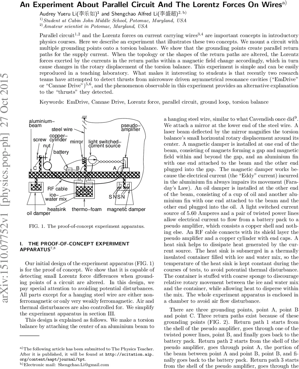
A torsion balance is constructed by suspending an aluminum beam from a steel wire, attaching a small mirror to the lower end of the wire, and using a laser beam reflected from the mirror to amplify tiny angular displacements. A magnetic damper consisting of strong neodymium magnets and an aluminum fin creates an eddy‑current drag that stabilizes the balance. The electrical circuit consists of a battery pack, a “pseudo‑amplifier” (a copper shell with no active components), two twisted power leads, an RF cable with its shield, a copper cylinder with end caps, and three deliberately placed grounding points labeled A, B, and C. Because of these three grounds, three parallel return paths (RP1, RP2, RP3) are formed from the pseudo‑amplifier back to the battery. The resistances of each path are measured, and the currents flowing through them are calculated for two configurations: RP3 disconnected (only RP1 and RP2 active) and RP3 connected (all three paths active). Typical currents are on the order of 1–3 A per path when the total supply current is 5.60 A.
Physical Principle
Each return path carries a current that experiences a Lorentz force F = I · L × B, where B is the sum of the Earth’s magnetic field and the field generated by the magnetic damper. Because the three paths have different geometries, the vector sum of the forces differs when RP3 is added or removed, producing a net torque on the torsion balance. The torque is observed as a change in the reflected laser spot, which is quantified in millidegrees of angular displacement.
Measurements and Statistical Analysis
Three sets of tests were performed.
Test A aligned the balance so that point A faced geographic north. RP3 was alternately connected and disconnected ten times (five repetitions each). The mean angular displacement was –45 mdeg for the disconnected case and –150 mdeg for the connected case, a difference of 105 mdeg. A two‑tailed t‑test gave p = 1.4 × 10⁻⁸, indicating a highly significant effect.
Test B repeated the same procedure with the balance oriented north, east, and northeast. The magnitude of the displacement change varied with orientation, demonstrating that the direction of the Earth’s magnetic field influences the net Lorentz torque.
Test C flipped the polarity of the magnetic damper while keeping the balance pointed north. Again RP3 was toggled (six trials total). The mean displacement difference was 19.1 mdeg, corresponding to an equivalent thrust of about 6.9 µN, with p = 0.0080.
Additional checks (e.g., placing a steel washer near point A, changing the shape of the RF cable, varying return‑path resistances) showed consistent trends: altering the current distribution or the geometry of the return conductors changes the balance’s rotation.
Simplified Version
The authors also present a reduced apparatus that replaces the non‑ferromagnetic components, laser, and precision mirror with a ceramic magnet, a bright torch, and a plain aluminum beam. A video demonstration is provided, confirming that the phenomenon can be reproduced with inexpensive, readily available parts.
Discussion and Relevance to EM‑Drive Experiments
The authors argue that the observed “thrusts” in EM‑drive and Cannae‑drive experiments could be largely explained by the same mechanism demonstrated here. In the NASA Eagleworks (Brady) experiment, the RF amplifier, microwave distributor, and the resonant cavity were all grounded to the torsion balance, and the RF cable geometry differed between the resonant‑cavity test and the resistive‑load null test. The authors note that the 5.6 A supply current was turned on and off together with the microwave signal, producing a net Lorentz force that the original authors attempted to subtract as a background. However, because the return‑path configuration changed, the subtraction may not have fully removed the Lorentz contribution. Similarly, the Dresden group’s measurements showed opposite rotations for opposite cavity orientations, but they did not explicitly account for the Earth’s magnetic field or possible interactions between the magnetron’s field and the supply current.
By quantifying the torque produced by modest currents (a few amperes) in modest magnetic fields (Earth’s field ≈ 50 µT plus the damper’s field), the present experiment demonstrates that forces on the order of 10 µN—comparable to the reported EM‑drive thrusts—can arise from purely electromagnetic effects unrelated to any exotic propulsion mechanism.
Conclusions and Educational Value
The experiment is low‑cost, reproducible, and provides a vivid illustration of how circuit topology, grounding, and magnetic fields combine to generate measurable mechanical forces. It serves as an excellent teaching tool for parallel‑circuit analysis, magnetic force calculations, and the importance of controlling systematic effects in precision measurements. Moreover, it offers a concrete, experimentally verified counter‑example to claims of thrust without reaction mass, reinforcing the principle that extraordinary claims require exhaustive accounting of all conventional physics.
Comments & Academic Discussion
Loading comments...
Leave a Comment