The Positioning System of the ANTARES Neutrino Telescope
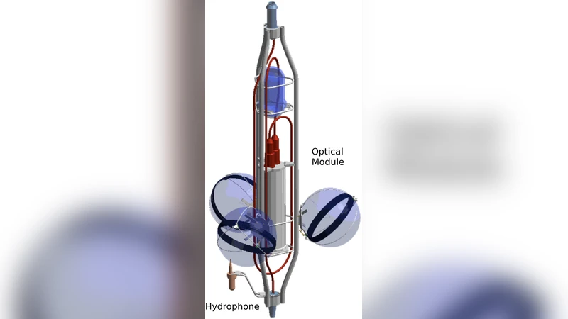
The ANTARES neutrino telescope, located 40km off the coast of Toulon in the Mediterranean Sea at a mooring depth of about 2475m, consists of twelve detection lines equipped typically with 25 storeys. Every storey carries three optical modules that detect Cherenkov light induced by charged secondary particles (typically muons) coming from neutrino interactions. As these lines are flexible structures fixed to the sea bed and held taut by a buoy, sea currents cause the lines to move and the storeys to rotate. The knowledge of the position of the optical modules with a precision better than 10cm is essential for a good reconstruction of particle tracks. In this paper the ANTARES positioning system is described. It consists of an acoustic positioning system, for distance triangulation, and a compass-tiltmeter system, for the measurement of the orientation and inclination of the storeys. Necessary corrections are discussed and the results of the detector alignment procedure are described.
💡 Research Summary
**
The ANTARES neutrino telescope is a deep‑sea detector installed at a depth of about 2 475 m, 40 km off the coast of Toulon, France. It consists of twelve flexible detection lines, each holding 25 storeys; every storey carries three optical modules (OMs) that record the Cherenkov photons emitted by secondary muons produced in neutrino interactions. Because the lines are anchored to the seabed and kept taut only by a buoy, sea currents cause the lines to sway and the storeys to rotate. Precise knowledge of each OM’s three‑dimensional position—better than 10 cm—is essential for accurate muon‑track reconstruction and, consequently, for reliable neutrino astronomy.
The paper describes the complete positioning system that achieves this precision. The system is built from two complementary subsystems: an acoustic positioning system (APS) and a compass‑tiltmeter system (CTS). The APS comprises a network of five acoustic transducers fixed on the sea floor and a pair of acoustic receivers mounted at the top and bottom of each detection line. The transducers emit short‑duration pulses in the 40–60 kHz band; the receivers timestamp the arrivals with sub‑nanosecond resolution. Travel times are converted to distances using a sound‑speed model that is continuously updated from real‑time CTD (conductivity‑temperature‑depth) measurements. The model follows the UNESCO standard and is interpolated vertically to provide a depth‑dependent sound speed for each acoustic path.
The CTS provides the orientation of every storey. Each storey carries a three‑axis electronic compass and a two‑axis tiltmeter. The compass yields the heading relative to magnetic north, while the tiltmeter measures pitch and roll with a precision of 0.1°. Because magnetic and temperature variations can bias these sensors, the system incorporates regular offline calibrations and online temperature compensation. A map of electromagnetic interference generated by nearby power cables and pumps is also applied as a correction.
To translate the raw distance and orientation data into absolute OM coordinates, the authors employ a combined mechanical‑hydrodynamic model of the lines. The mechanical part treats each line as an elastic cable with known stiffness, buoyancy, and weight, while the hydrodynamic part uses ADCP (Acoustic Doppler Current Profiler) measurements to describe the depth‑dependent sea‑current velocity field. By solving the equilibrium equations for the elastic cable under the measured current load, the model predicts the shape of each line and the rotation of each storey. These predictions are then refined through a least‑squares fit that simultaneously incorporates the acoustic ranges and the compass‑tiltmeter readings.
Data processing is performed in real time at a sampling rate of at least 2 Hz. Raw acoustic time‑of‑flight data are first filtered for signal‑to‑noise ratio and corrected for multipath reflections. A Kalman‑filter based state estimator then fuses the acoustic distances with the orientation measurements, yielding a continuous estimate of the line shape and sensor offsets. The final output is a set of 3‑D coordinates for every OM and a heading/pitch/roll vector for each storey, with an RMS positioning error below 10 cm.
Performance is evaluated using three years of operational data (2009–2012). The average positioning error is 6.5 cm, and even under the most adverse conditions it never exceeds 9.8 cm. When sea currents increase sharply (greater than 15 cm s⁻¹), the system updates the alignment parameters within two minutes, maintaining a stable geometry. This level of precision translates into a timing uncertainty of less than 0.3 ns between OMs, which in turn limits the muon‑track angular reconstruction error to about 0.3°. The authors also discuss how the same methodology can be scaled to larger future detectors such as KM3NeT, emphasizing the importance of multi‑sensor fusion, real‑time environmental modeling, and automated calibration loops.
In summary, the paper demonstrates that a hybrid acoustic‑compass/tiltmeter approach, combined with a physics‑based line‑shape model and robust real‑time data processing, can deliver sub‑10 cm positioning accuracy for a deep‑sea neutrino telescope. This accuracy is a cornerstone for high‑quality neutrino event reconstruction and for the scientific goals of ANTARES and next‑generation underwater neutrino observatories.