Kawasaki dynamics with two types of particles: stable/metastable configurations and communication heights
This is the second in a series of three papers in which we study a two-dimensional lattice gas consisting of two types of particles subject to Kawasaki dynamics at low temperature in a large finite box with an open boundary. Each pair of particles oc…
Authors: Frank den Holl, er, Francesca R. Nardi
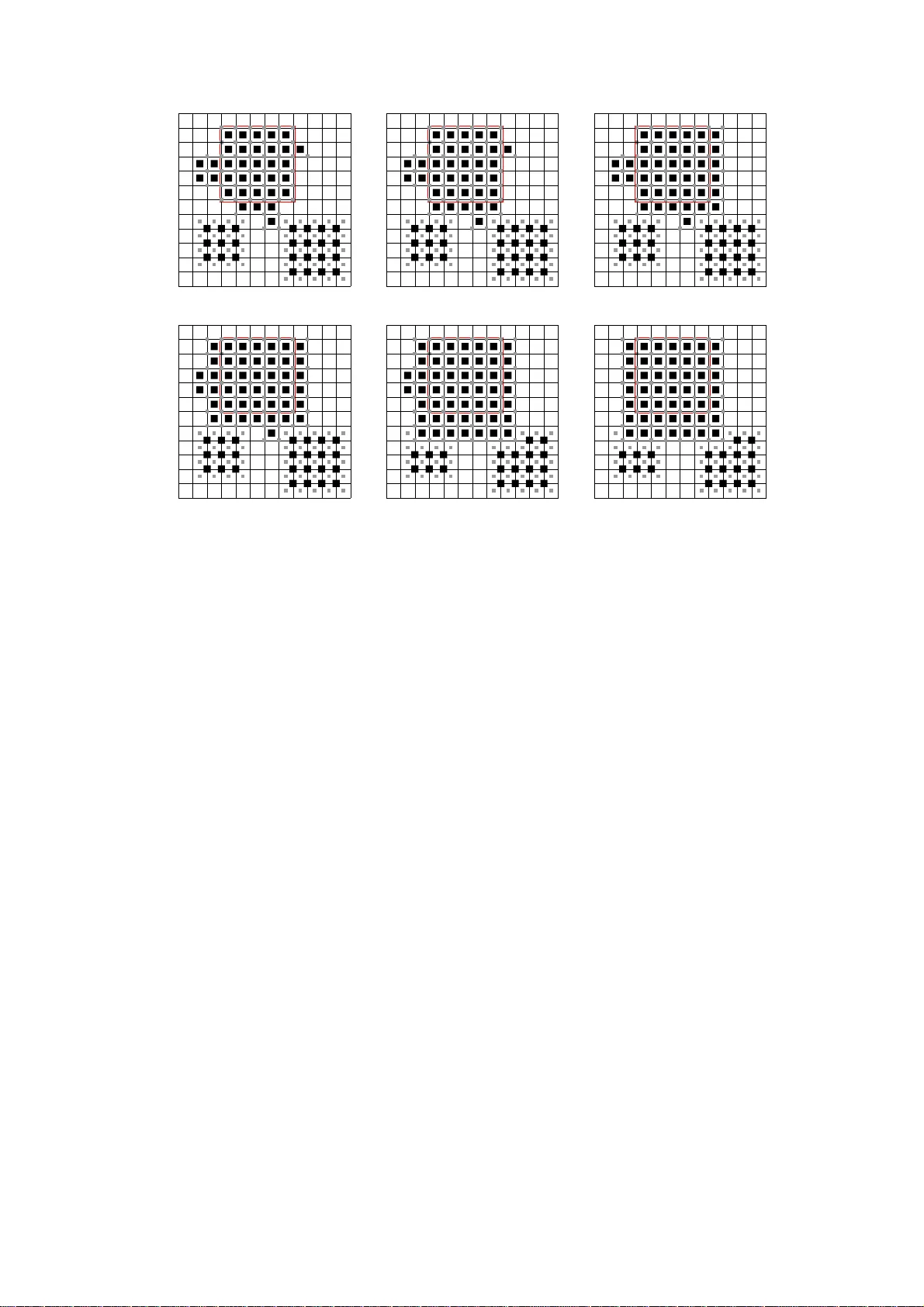
Ka w asaki dynamics wi th t w o t yp es of particles: stable/met astable configuratio ns and comm unicatio n heigh ts F. den Hollander 1 2 F.R. Nardi 3 2 A. T roiani 1 August 9, 2021 Abstract This is the second in a series of three pap ers in whic h we study a t wo-dimensional lattice gas consisting of tw o t yp es of pa rticles sub ject to Ka wasa k i dynamics at low temp erature in a large finite b o x with an op en bound ary . Each pair of p arti cles occupying neighboring sites has a negative binding energy p rovided their types are different, while each particle has a p os itive activ ation energy that depends on its type. There is no binding energy betw een particles of the same type. A t the b oundary of th e box particles are created and annihilated i n a wa y that rep resents the presence of an infinite gas re servo ir. W e start t h e dy namics from the empty b o x and are interested in the transition time t o the full b ox. This transition is triggered by a critical droplet app earing somewhere in the b o x . In the first pap er we identified the parameter range for which the system is metastable, show ed that the fi rst entrance distribution on the set of critical droplets is u nif orm, computed the exp ected transition t ime up to and including a multiplica t iv e factor of order one, and prov ed that th e nuclea tion time divided by its exp ectation is ex p onential ly distributed, all in the limit of low temp era t u re. These results w ere pro ved under thr e e hyp otheses , and invo lve thr e e mo del-dep endent quantities : th e energy , the shape and the number of critical droplets. In t h e second pap er we prov e the first and the second hyp o thesis and identify the energy of critical droplets. In the th i rd paper w e settle the rest. Both the second and the t hird pap er deal with u n derstanding the ge ometric pr op erties of sub criti cal, critical and sup ercritical droplets, which are crucial in determining the metastable b eha vior of the system, as explained in the first pap er. The geometry turns out to b e considerably more complex than for Kaw asaki dynamics with one type of particle, for whic h an extensive literature exists. The main motiv ation b ehind our w ork is to understand metastabilit y of multi- type particle systems. MSC2010. 60K35, 82C20 82C22 82C26 05B50 Key wor ds and phr ases. Lattice gas, Multi-typ e p article systems, Ka wasaki dynamics, Metastabil - it y , Critical configurations, P olyominoes, D is crete isoperimetric inequ al ities. 1 Mathematical Institute, Leiden Unive rsity , P .O. Box 9512, 2300 RA Leiden, The Netherlands 2 EURANDOM, P .O. Box 513, 56 00 MB Eindhov en, The Netherlands 3 T ech ni sc he Universiteit Eindho ven, P .O. Box 513 , 5600 MB Eindhov en, The N e therlands 1 1 In tro duction Section 1.1 defines the mo del, Section 1.2 intro duces basic notation, Section 1.3 sta tes the main theo- rems, while Section 1.4 discuss e s the main theorems a nd provides further p erspectives. 1.1 Lattice gas sub ject to Kaw asaki dynamics Let Λ ⊂ Z 2 be a lar g e box centered at the origin (later it will b e convenien t to choose Λ rhombus- shap ed). Let ∂ − Λ = { x ∈ Λ : ∃ y / ∈ Λ : | y − x | = 1 } , ∂ + Λ = { x / ∈ Λ : ∃ y ∈ Λ : | y − x | = 1 } , (1.1) be the int e r nal, res pectively , ex ternal b oundary o f Λ , and put Λ − = Λ \ ∂ − Λ and Λ + = Λ ∪ ∂ + Λ . With ea c h site x ∈ Λ w e asso ciate a v ariable η ( x ) ∈ { 0 , 1 , 2 } indicating the absence of a par ticle or the presence of a particle of type 1 or type 2 . A configuration η = { η ( x ) : x ∈ Λ } is an element of X = { 0 , 1 , 2 } Λ . T o each configur ation η w e a s sociate an energy given by the Ha milt o nian H = − U X ( x,y ) ∈ Λ ∗ , − 1 { η ( x ) η ( y )=2 } + ∆ 1 X x ∈ Λ 1 { η ( x )=1 } + ∆ 2 X x ∈ Λ 1 { η ( x )=2 } , (1.2) where Λ ∗ , − = { ( x, y ) : x, y ∈ Λ − , | x − y | = 1 } is the set of non-oriented b onds inside Λ − , − U < 0 is the binding ener gy b et ween neig h b oring par ticles of differ ent t yp es inside Λ − , and ∆ 1 > 0 and ∆ 2 > 0 are the activation ener gies of par ticles o f type 1 , r espectively , 2 inside Λ . W.l.o.g. we will ass ume that ∆ 1 ≤ ∆ 2 . (1.3) The Gibbs measure ass ociated with H is µ β ( η ) = 1 Z β e − β H ( η ) , η ∈ X , (1.4) where β ∈ (0 , ∞ ) is the inverse temper ature and Z β is the normalizing partition sum. Kaw asa ki dynamics is the co ntin uous -time Marko v pro cess, ( η t ) t ≥ 0 with state space X who se tran- sition rates are c β ( η , η ′ ) = e − β [ H ( η ′ ) − H ( η )] + , η , η ′ ∈ X , η 6 = η ′ , η ↔ η ′ , (1.5) where η ↔ η ′ means that η ′ can b e obtained from η by one of the following mov es: • int e r c hanging 0 and 1 or 0 a nd 2 b et ween t wo neighboring sites in Λ (“hopping of particles in Λ ” ), • changing 0 to 1 or 0 to 2 in ∂ − Λ (“creation of particles in ∂ − Λ ”), • changing 1 to 0 or 2 to 0 in ∂ − Λ (“annihilation of particles in ∂ − Λ ”), and c β ( η , η ′ ) = 0 otherwise. No te that this dynamics prese rv es particles in Λ , but allows particles to b e created and annihilated in ∂ − Λ . Think of the latter as describing particles ent ering and exiting Λ along non-oriented b onds betw e e n ∂ + Λ a nd ∂ − Λ (the rates of these mov es ar e a ssocia ted with the b onds rather than with the s it es). The pa irs ( η , η ′ ) with η ↔ η ′ are called c ommu nic ating c onfi gur ations , the transitions b et ween them are called al lowe d moves . Note that particles in ∂ − Λ do not interact: the in ter action only works in Λ − . The dynamics defined by (1 .2) a nd (1.5 ) mo dels the b ehavior in s ide Λ of a lattice gas in Z 2 , consisting of tw o t yp es of particles sub ject to rando m ho pping with hard- c o re r epulsion and with binding b et ween differe nt neighboring types. W e may think o f Z 2 \ Λ as a n infinite r eservoir that keeps 2 the particle densities fixed at ρ 1 = e − β ∆ 1 and ρ 2 = e − β ∆ 2 . In the ab ov e mo del this reservoir is replace d b y a n op en b oundary ∂ − Λ , where particles ar e crea ted a nd a nnih ila ted at a ra te that matches these densities. Th us , the dyna mics is a finite- s t ate Ma r k ov pro cess, ergo dic and reversible with resp ect to the Gibbs measure µ β in (1.4). Note that there is no binding energy betw ee n neig h b oring particles of the same type. Conse q uen tly , the mo del do es not r educe to K awasaki dyna mics for one t ype o f par ti c le when ∆ 1 = ∆ 2 . 1.2 Notation T o state our main theor e ms in Section 1.3, we need so me notation. Definition 1.1 (a) is the c onfigur ation wher e Λ is empty. (b) ⊞ is the set c onsisting of the t wo c onfigur ations wher e Λ is fil le d with the lar gest p ossible che ckerb o ar d dr oplet such that al l p articles of typ e 2 ar e surr ounde d by p articles of typ e 1 . (c) ω : η → η ′ is any p ath of al lowe d moves fr om η ∈ X to η ′ ∈ X . (d) Φ ( η , η ′ ) is the c ommunic ation height b etwe en η , η ′ ∈ X define d by Φ ( η , η ′ ) = min ω : η → η ′ max ξ ∈ ω H ( ξ ) , (1.6) and Φ ( A, B ) is its ext ensio n t o non-empty set s A, B ⊂ X define d by Φ ( A, B ) = min η ∈ A ,η ′ ∈ B Φ ( η , η ′ ) . (1.7) (e) V η is the stability level of η ∈ X define d by V η = Φ ( η , I η ) − H ( η ) , (1.8) wher e I η = { ξ ∈ X : H ( ξ ) < H ( η ) } is the set of c onfigur ations with ener gy lower than η . (f ) X stab = { η ∈ X : H ( η ) = min ξ ∈ X H ( ξ ) } is t he set of st a ble c onfigur ations, i.e., the set of c onfigu- r ations with mininal ener gy. (g) X meta = { η ∈ X : V η = ma x ξ ∈ X \X stab V ξ } is t h e set of m et astab le c onfigur ations, i.e., the set of non-stable c onfigur ations with maximal stability level. (h) Γ = V η for η ∈ X meta (note that η 7→ V η is c onstant on X meta ), Γ ⋆ = Φ ( , ⊞ ) − H ( ) (n ote that H ( ) = 0 ). In [3] we were interested in the transition o f the Kawasaki dynamics from to ⊞ in the limit a s β → ∞ . This tr ansition, which is viewed a s a cr ossov er fro m a “gas pha s e” to a “liquid phase ”, is triggered by the appe a rance of a critic al dr oplet somewher e in Λ . The critical droplets fo r m a s ubse t of the set of configur a tions realizing the energetic minimax o f the paths o f the K a wasaki dynamics fro m to ⊞ , which all hav e energy Γ ⋆ bec a use H ( ) = 0 . In [3] we show e d that the first entrance distribution on the set o f cr itica l dr oplets is uniform, computed the exp ected transition time up to and including a multiplicativ e factor of order o ne, and prov ed that the nucleation time divided by its e x pectation is exp onen tially distributed, all in the limit a s β → ∞ . These res ults, which a r e typical for meta s table b ehavior, were prov ed under thr e e hyp otheses : (H1) X stab = ⊞ . (H2) There exists a V ⋆ < Γ ⋆ such that V η ≤ V ⋆ for all η ∈ X \{ , ⊞ } . (H3) A hypothesis a bout the shap e of the co nfigurations in the e s sen tial gate fo r the transition fro m to ⊞ (for details see [3 ]). Hypo theses (H1–H3) are the ge ometric input that is needed to derive the main theorems in [3] with the help of the p otential-the or etic appr o ach to metastability as outlined in Bovier [2]. In the present pap er we prove (H1–H2) and identify the energy Γ ⋆ of critical droplets. In [4] we settle the rest. 3 Lemma 1 . 2 (H1–H2) imply that V = Γ ⋆ , and henc e that X meta = and Γ = Γ ⋆ . Pr o of . By Definition 1.1(e–h) and (H1), ⊞ ∈ I , which implies that V ≤ Γ ⋆ . W e show that (H2) implies V = Γ ⋆ . The pro of is by contradiction. Supp ose that V < Γ ⋆ . Then, by Definition 1.1(h), there exists a η 0 ∈ I \ ⊞ such that Φ ( , η 0 ) − H ( ) < Γ ⋆ . But (H2), toge ther with the finiteness of X , implies that there exist an m ∈ N and a seq uence η 1 , . . . , η m ∈ X with η m = ⊞ such that η i +1 ∈ I η i and Φ ( η i , η i +1 ) ≤ H ( η i ) + V ⋆ for i = 0 , . . . , m − 1 . Ther efore Φ ( η 0 , ⊞ ) ≤ max i =0 ,...,m − 1 Φ ( η i , η i +1 ) ≤ max i =0 ,...,m − 1 [ H ( η i ) + V ⋆ ] = H ( η 0 ) + V ⋆ < H ( ) + Γ ⋆ , (1.9) where in the first inequality we use that Φ ( η , σ ) ≤ max { Φ ( η , ξ ) , Φ ( ξ , σ ) } for all η , σ , ξ ∈ X , and in the last inequality that η 0 ∈ I and V ⋆ < Γ ⋆ . It follows that Φ ( , ⊞ ) − H ( ) ≤ max { Φ ( , η 0 ) − H ( ) , Φ ( η 0 , ⊞ ) − H ( ) } < Γ ⋆ , (1.10) which co n tradicts Definition 1.1(h). Observe that the pro of us es that X meta consists of a single co nfig- uration. Hypo theses (H1–H2) imply that ( X meta , X stab ) = ( , ⊞ ) , and that the highest energy barr ier b e- t ween any t wo configur a tions in X is the o ne sepa r ating and ⊞ , i.e., ( , ⊞ ) is the unique metastable p air . Hyp othesis (H3) is nee ded only to find the as ymptotics of the prefactor o f the expec ted tra nsition time in the limit a s Λ → Z 2 . The main theorems in [3 ] in volve thr e e mo del-dep endent quant ities : the energy , the shap e a nd the num b er of critical droplets. 1.3 Main theorems In [3] it was shown that ∆ 1 + ∆ 2 < 4 U is the metastable r e gion , i.e., the region o f parameters for which is a lo cal minim um but not a global minimu m of H . Mor eo ver, it was a rgued that within this region the subregion where ∆ 1 , ∆ 2 < U is o f no in ter est b ecause the critical droplet co nsists of tw o free particles, one of type 1 and one of type 2 . Therefore the pr op er metastable r e gion is 0 < ∆ 1 ≤ ∆ 2 , ∆ 1 + ∆ 2 < 4 U , ∆ 2 ≥ U, (1.11) as indicated in Fig. 1. Figure 1: Prop er metasta ble region. In this present pap er, the analysis will b e carried out for the subr egion where 0 < ∆ 1 < U, ∆ 2 − ∆ 1 > 2 U, ∆ 1 + ∆ 2 < 4 U, (1.12) as indicated in Fig. 2 . Note : The second a nd third res triction imply the firs t restric tio n. Nevertheless, we write all three b ecause each plays a n imp ortan t ro le in the sequel. The following three theorems are the main result of the pre s en t pap er and are v alid s ub ject to (1.12). W e write ⌈·⌉ to denote the uppe r in teger part. 4 Figure 2: Subregion of the pro per metastable regio n given by (1.12). Theorem 1 .3 X stab = ⊞ . Theorem 1 .4 Ther e exists a V ⋆ ≤ 10 U − ∆ 1 such that V η ≤ V ⋆ for al l η ∈ X \ { , ⊞ } . Conse quent ly , if Γ ⋆ > 10 U − ∆ 1 , then X meta = and Γ = Γ ⋆ . Theorem 1 .5 Γ ⋆ = − [ ℓ ⋆ ( ℓ ⋆ − 1) + 1](4 U − ∆ 1 − ∆ 2 ) + (2 ℓ ⋆ + 1)∆ 1 + ∆ 2 with ℓ ⋆ = ∆ 1 4 U − ∆ 1 − ∆ 2 ∈ N . (1.13) Theorem 1 .3 settles hypothesis (H1) in [3 ], Theorem 1.4 settles hypothesis (H2) in [3] when Γ ⋆ > 10 U − ∆ 1 , while Theorem 1.5 identifies Γ ⋆ . As so on as V ⋆ < Γ ⋆ , the energy landsca pe do es not contain w ells deeper than thos e surr ounding and ⊞ . Theor ems 1.3 a nd 1.4 imply that this o ccurs at least when Γ ⋆ > 10 U − ∆ 1 , while Theorem 1.5 iden tifies Γ ⋆ and allows us to exhibit a further subregion of (1.12) where the latter inequality is satisfied. This further subregio n cont a ins the shaded re g ion in Fig. 3. Figure 3: The para meter region where Γ ⋆ > 10 U − ∆ 1 contains the shaded regio n. 1.4 Discussion 1. In Section 4 w e will see that the critic al dr oplets for the crossover from to ⊞ consist of a rhombus- shap e d che ckerb o ar d with a pr otub er anc e plus a fr e e p article , as indicated in Fig. 4. A more detailed description will b e given in [4]. 2. Abbreviate ε = 4 U − ∆ 1 − ∆ 2 (1.14) 5 Figure 4 : A critical dro plet. Light-shaded s q uares are pa rticles of type 1 , dark-sha ded squar e s are particles of type 2 . The particles of type 2 form an ℓ ⋆ × ( ℓ ⋆ − 1) quasi-square with a protub erance attached to one of its long est sides, and ar e all surrounded by particles of type 1 . In a ddit io n, there is a free particle of t yp e 2 . As so on as this fr e e particle attaches itself “ properly” to a particle of type 1 the dynamics is “ov er the hill” (see [3], Section 2.3 , item 3 ). and write ℓ ⋆ = (∆ 1 /ε ) + ι with ι ∈ [0 , 1 ) . Then an easy computation shows that Γ ⋆ = (∆ 1 ) 2 /ε + ∆ 1 + 4 U + ει (1 − ι ) . F ro m this we see that ℓ ⋆ ∼ ∆ 1 /ε, Γ ⋆ ∼ (∆ 1 ) 2 /ε, ε ↓ 0 . (1.15) The limit ε ↓ 0 co rrespo nds to the we akly sup ersatur ate d regime, where the lattice g as wan ts to condensate but the energetic thres ho ld to do so is high (b ecause the critical droplet is larg e). F rom the viewp oin t of metastability this reg ime is the most interesting. The shaded reg io n in Fig. 3 captures this r egime for all 0 < ∆ 1 < U . This reg ion cont a ins the set of parameters where (∆ 1 ) 2 /ε + ∆ 1 + 4 U > 10 U − ∆ 1 , i.e., ε/U < (∆ 1 /U ) 2 / [6 − 2 (∆ 1 /U )] . 3. The simplifying feature s of (1.12) ov er (1.1 1 ) ar e the following: ∆ 1 < U implies that each time a particle of type 1 enters Λ and attaches itself to a par ti cle of type 2 in a dro plet the energ y go es down, while ∆ 2 − ∆ 1 > 2 U implies that no particle of type 2 sits o n the b oundary of a dro plet that has minimal ener gy given the num b er o f par ticles o f type 2 in the droplet. In [3] we co nj ectured tha t the metastability res ults presented there a c tua lly hold throug hout the region given b y (1 .11) , even though the critical droplets will b e differ ent when ∆ 1 ≥ U . As will b ecome clear in Section 3, the constraint ∆ 1 < U ha s the effect tha t in all config urations that ar e lo cal minima of H all par ticles on the b oundary of a droplet are of type 1 . It will turn out that such co nfigurations co ns ist of a single rhombus-shap e d che ckerb o ar d dr oplet . W e exp ect that as ∆ 1 increases from U to 2 U there is a gr adual transition from a rhombus-shaped chec kerb oard critical droplet to a squar e-shaped chec kerb o ard critical droplet. This is one of the reasons why it is difficult to go b ey ond (1.12). 4. What makes Theorem 1.4 ha r d to prove is that the estimate on V η has to be uniform in η / ∈ { , ⊞ } . In configura tions co n taining several droplets and/o r droplets close to ∂ − Λ there may b e a lack of free space making the motion of par ticles inside Λ difficult. The mechanisms developed in Section 5 allow us to rea lize an ener gy r e duction to a configuration that lies on a suitable r efer enc e p ath for the nucle ation within an energ y barrier 10 U − ∆ 1 also in the absence of free space aro und ea c h droplet. W e will se e in Section 5 that for droplets sufficient ly far awa y fr o m other droplets and from ∂ − Λ a reduction within an energ y ba rrier ≤ 4 U + ∆ 1 is p ossible. Thus, if we would b e able to control the configurations that fail to hav e this prop ert y , then we would hav e V ⋆ ≤ 4 U + ∆ 1 and, co nsequen tly , would hav e X meta = a nd Γ = Γ ⋆ throughout the subregion given by (1.1 2 ) be c a use Γ ⋆ > 4 U + ∆ 1 . Another way of phrasing the last observ ation is the fo llo wing. W e view the “liquid phase” as the configuration filling the entire b o x Λ . If, instead, we w o uld let the liquid phase corr espond to the set 6 of co nfigurations filling most of Λ but staying aw ay from ∂ − Λ , then the metastability results derived in [3] would apply throug hout the subreg io n given by (1.12). 5. Theore ms 1 .3 and 1.5 can actually b e prov ed without the restr iction ∆ 2 − ∆ 1 > 2 U . How ever, remov al of this restriction ma k es the task of showing that in droplets with minimal energy all particles of type 2 ar e surr ounded by pa rticles of type 1 more inv olved than wha t is done in Section 3. W e omit this extension, since the res tr iction ∆ 2 − ∆ 1 > 2 U is needed for Theorem 1.4 anyw ay . Outline. Section 2 contains preparations. Theor ems 1.3–1.5 a re proved in Sections 3– 5 , resp ectiv ely . The pro ofs are pur ely c ombinatorial , a nd are r ather inv olved due to the pre s ence of t wo types of particles ra ther than one. Sections 3–4 deal with statics a nd Section 5 with dynamics . Section 5 is tech nica lly the ha r dest a nd takes up ab out half o f the pap er. More deta iled outlines a re given at the beg inning of ea c h section. 2 Co ordinates, definitions and p ol y omino es Section 2.1 introduces tw o co ordinate systems that a re used to describ e the pa r ticle configur a tions: standard a nd dual. Section 2.2 lists the main geometric definitions that are needed in the rest of the pap er. Section 2.3 proves a lemma ab out polyomino es (finite unio ns of unit squares) and Section 2.4 a lemma abo ut 2 –tiled clusters (c heckerboar d configura tions where all particles of type 2 a re surrounded b y pa r ticles o f t y pe 1 ). These lemmas a re needed in Section 3 to ident ify the dro plets of minimal energy given the num b er o f par ticles o f type 2 in Λ . 2.1 Co ordinates 1. A site i ∈ Λ is identifi ed by its s t anda r d c o or dinates ( x 1 ( i ) , x 2 ( i )) , and is called o dd when x 1 ( i )+ x 2 ( i ) is o dd and even when x 1 ( i ) + x 2 ( i ) is even. The standard co ordinates of a particle p in Λ are denoted b y x ( p ) = ( x 1 ( p ) , x 2 ( p )) . The p arity o f a par ticle p is defined as x 1 ( p ) + x 2 ( p ) + η ( x ( p )) mo dulo 2 , and p is said to b e o dd when the parity is 1 and even when the parity is 0 . 2. A site i ∈ Λ is also identified b y its dual c o or dinates u 1 ( i ) = x 1 ( i ) − x 2 ( i ) 2 , u 2 ( i ) = x 1 ( i ) + x 2 ( i ) 2 . (2.1) T w o sites i and j a re said to be adjac ent , written i ∼ j , when | x 1 ( i ) − x 1 ( j ) | + | x 2 ( i ) − x 2 ( j ) | = 1 or, equiv a len tly , | u 1 ( i ) − u 1 ( j ) | = | u 2 ( i ) − u 2 ( j ) | = 1 2 (see Fig. 5). 3. F or co n venience, we take Λ to be the ( L + 3 2 ) × ( L + 3 2 ) dua l square centered at the o rigin for some L ∈ N with L > 2 ℓ ⋆ (to allow for H ( ⊞ ) < H ( ) ; see Section 3.1). Particles interact o nly inside Λ − , which is the ( L + 1 2 ) × ( L + 1 2 ) dual squa r e centered at the or igin. This dua l sq uare, a rhombus in standard co ordinates, is conv enient b ecause the lo cal minima o f H a re rho m bus-shap ed as well (see Section 3). 2.2 Definitions 1. A site i ∈ Λ is sa id to be lattic e-c onne cting in the configur ation η if there exis ts a la ttice pa th λ from i to ∂ − Λ suc h that η ( j ) = 0 for a ll j ∈ λ with j 6 = i . W e say that a pa rticle p is lattice-co nnecting if x ( p ) is a lattice-co nnecting site. 2. T wo particles in η a t s ites i and j ar e called c onne cte d if i ∼ j and η ( i ) η ( j ) = 2 . If tw o particles p 1 and p 2 are connected, then we say that there is an active b ond b b et ween them. The bo nd b is said to be incident to p 1 and p 2 . A pa rticle p is sa id to b e satur ate d if it is co nnected to four other particles, i.e., there a re four active b onds inciden t to p . The suppor t of the co nfiguration η , i.e., the union of the 7 (a) (b) Figure 5: A configuration repres en ted in: (a) standar d co ordinates; (b) dual co ordinates. Light-shaded squares are particles of type 1 , dark-shaded squares are particles of t yp e 2 . In dual co ordinates, particles of type 2 are r epresen ted by larger squar e s than particles of type 1 to exhibit the “tiled structure” o f the configura ti on. unit s quares centered at the o ccupied sites o f η , is denoted by supp ( η ) . F or a configura tio n η , n 1 ( η ) and n 2 ( η ) denote the num b er of particles of type 1 and 2 in η , and B ( η ) denotes the n umber of active bo nds. The energ y o f η eq uals H ( η ) = ∆ 1 n 1 ( η ) + ∆ 2 n 2 ( η ) − U B ( η ) . 3. Let G ( η ) b e the gr aph asso ciated with η , i.e., G ( η ) = ( V ( η ) , E ( η )) , where V ( η ) is the set o f s it e s i ∈ Λ s uc h that η ( i ) 6 = 0 , and E ( η ) is the set o f the pairs { i , j } , i, j ∈ V ( η ) , s uc h that the particles at sites i and j a re connected. A configur ation η ′ is called a sub c onfigur ation o f η , written η ′ ≺ η , if η ′ ( i ) = η ( i ) for all i ∈ Λ such that η ′ ( i ) > 0 . A sub c o nfiguration c ≺ η is a cluster if the graph G ( c ) is a maxima l connected compo nen t of G ( η ) . The se t of non-saturated particles in c is called the b oundary of c , and is denoted by ∂ c . Cle a rly , a ll particles in the same c lus ter hav e the same parity . Therefo r e the concept of par it y extends from particles to clusters. 4. F or a site i ∈ Λ , the tile cent er ed at i , denoted by t ( i ) , is the set o f five sites consisting of i and the four sites a dj a cen t to i . If i is a n even s ite, then the tile is said to b e even, otherwis e the tile is said to b e o dd. The five sites of a tile are lab eled a , b , c , d , e as in Fig. 6. The sites lab eled a , b , c , d are called jun ct i on sites . If a particle p sits at site i , then t ( i ) is also denoted b y t ( p ) and is ca lled the tile asso ciated with p . In standard co ordinates, a tile is a squa r e of size √ 2 . In dual co ordinates, it is a unit square. 5. A tile who se cen tr al site is o ccupied by a particle of type 2 and who se junction sites a re o ccupied by particles of type 1 is called a 2 –tile (see Fig. 6). T wo 2 –tiles a r e said to b e adjac e nt if their particles of t y p e 2 hav e dual distance 1. A hor izon tal (vertical) 1 2 –b ar is a maximal sequence of a dj a cen t 2 –tiles all having the sa me horizontal (vertical) co ordinate. If the sequence has length 1 , then the 12 –ba r is called a 2 –tile d pr otub er anc e . A cluster co n taining at leas t one particle o f type 2 such that all particles of type 2 a re saturated is said to b e 2 –tiled. A 2 –tiled co nfiguration is a co nfiguration consis ting of 2 –tiled clusters only . (a) (b) (c) (d) Figure 6: Tiles: (a) standar d repres e n tation o f the lab els of a tile; (b) standard representation of a 2 –tile; (c) dual re presen tation o f the lab els of a tile; (d) dual r epresen tation o f a 2 –tile . 8 6. The tile supp ort o f a config uration η is defined as [ η ] = [ p ∈ 2 ( η ) t ( p ) , (2.2) where 2 ( η ) is the set o f particles o f type 2 in η . Obviously , [ η ] is the union of the tile suppo rts of the clusters making up η . F or a standard cluster c the dual p erimeter , denoted by P ( c ) , is the length of the Euclidean b oundary of its tile s upp ort [ c ] (which includes an inner b oundary when c contains holes). The dua l p erimeter P ( η ) of a 2 –tiled configura tio n η is the sum of the dual p erimeters of the clusters making up η . 7. V ⋆,n 2 is the set of co nfigurations such that in Λ −− the num b e r of pa rticles of type 2 is n 2 . V 4 n 2 ⋆,n 2 is the set o f configuratio ns suc h that in Λ −− the n umber of particles of type 2 is n 2 , the num ber o f active bo nds is 4 n 2 , and there is no is o lated particle of t yp e 1 . In other words, V 4 n 2 ⋆,n 2 is the set of 2 – ti led configurations with n 2 particles of type 2 . The lower index ⋆ is used to indicate that configurations in these sets ca n have an a rbitrary num b er of pa rticles of t yp e 1 . A config uration η is ca lled standar d if η ∈ V 4 n 2 ⋆,n 2 , and its tile supp ort is a standard p olyomino in dual co ordinates (see Definition 2 .1 b elow for the definition of a standard po ly omino). 8. A unit hole is an empty site s uch that all four o f its neigh bo rs are o ccupied b y pa rticles of the same t y p e (either all of type 1 or a ll o f type 2 ). An empty site with three neig h b oring sites o ccupied by a particle of type 1 is called a go o d dual c orner . In the dual repr esen tation a go od dual corner is a concav e corner (see Fig. 7). 2.3 A lemma on p oly omino es The tile supp ort of a cluster c can b e represented by a p olyomino, i.e., a finite union of unit square s. The following notation is used: ℓ 1 ( c ) = width of c (= num b er of columns). ℓ 2 ( c ) = heig h t of c (= num b er of rows). v i ( c ) = num b er of vertical edges in the i -th non-empty row of c . h j ( c ) = num b er of horizo n tal edg es in the j - th non-empty co lumn of c . P ( c ) = length of the p erimeter of c . Q ( c ) = num b er o f holes in c . ψ ( c ) = n umber of conv ex corners of c . φ ( c ) = num b er o f concave co rners of c . Note that ψ ( c ) = P N ( c ) i =1 ψ ( i ) and φ ( c ) = P N ( c ) i =1 φ ( i ) , w her e N ( c ) is the num b er of vertices in the po ly omino representing c . If t wo edges e 1 and e 2 are incident to vertex i at a right angle with a unit square inside and no unit sq ua res outside, then ψ ( i ) = 1 a nd φ ( i ) = 0 (Fig. 7(a)). O n the o ther hand, if there is no unit squa re ins ide and three unit squares outside, then ψ ( i ) = 0 and φ ( i ) = 1 (Fig. 7(b)). If four edge s e 1 , e 2 , e 3 , e 4 are incident to vertex i , with tw o unit squar e s in opp osite angles, then ψ ( i ) = 0 a nd φ ( i ) = 2 (Fig. 7(c)). Definition 2.1 [Alonso and Cerf [1].] A p olyomino is c al le d monotone if its p erimeter is e qual to the p erimeter of its cir cumscribing r e ctangle. A p olyomino whose su pp ort is a quasi-squar e (i.e., a r e ctangle whose side lengths differ by at most one), with p ossibly a b ar attache d to one of its longest sides, is c al le d a standar d p olyomino. 9 (a) (b) (c) Figure 7 : Corners of p oly omino es: (a) one convex corner ; (b) one concav e cor ner; (c) tw o concav e corners. Shaded mean o ccupied by a unit squar e. In the sequel, a key ro le will b e play ed by the quantit y T ( c ) = 2 P ( c ) + [ ψ ( c ) − φ ( c )] = 2 P ( c ) + 4 − 4 Q ( c ) . (2.3) Lemma 2 . 2 (i) Al l p olyomino es c with a fixe d n umb er of monomino es minimizing T ( c ) ar e single- c omp onent monotone p olyomino es of minimal p erimeter, which include t h e standar d p olyomino es. (ii) If t he numb er of monomino es is ℓ 2 , ℓ 2 − 1 , ℓ ( ℓ − 1) or ℓ ( ℓ − 1) − 1 for some ℓ ∈ N \{ 1 } , t hen the standar d p olyomino es ar e the only minimizers of T ( c ) . Pr o of . In the pro of we assume w.l.o.g. that the p oly o mino consists of a s ing le cluster c . (i) The pro of uses pro jection. Pick any no n-monotone cluster c . Le t ˜ c = ( π 2 ◦ π 1 )( c ) , (2.4) where π 2 and π 1 denote the vertical, resp ectiv ely , the hor izon tal pro jection of c . The effect of vertical and hor izon tal pro jection is illustrated in Fig. 8. By c o nstruction, ˜ c is a monotone p oly omino (see e.g. the statement on F err ers diagra ms in the pro of of Alonso and Cerf [1], Theorem 2.2). Figure 8: Effect of vertical and horizo ntal pro jection. Suppos e first that Q ( c ) = 0 . Then T ( c ) = 2 P ( c ) + 4 . Since c is not monotone, we hav e P ( ˜ c ) < P ( c ) , and so c is not a minimizer of T ( c ) . Suppos e next that Q ( c ) ≥ 1 . Since P ( c ) = ℓ 2 ( c ) X i =1 v i ( c ) + ℓ 1 ( c ) X j =1 h j ( c ) (2.5) and every hole b elongs to at least one r ow a nd one co lum n, we hav e P ( c ) ≥ 2[ ℓ 1 ( c ) + ℓ 2 ( c )] + 4 Q ( c ) . (2.6) On the o ther hand, since ˜ c is a monotone p oly omino, we hav e v i (˜ c ) = h j (˜ c ) = 2 for all i and j , and so P ( ˜ c ) = 2 [ ℓ 1 (˜ c ) + ℓ 2 (˜ c )] . (2.7) Moreov er , since ℓ 1 (˜ c ) ≤ ℓ 1 ( c ) and ℓ 2 (˜ c ) ≤ ℓ 2 ( c ) , we ca n combine (2.6–2.7) to ge t P ( ˜ c ) − P ( c ) ≤ − 4 Q ( c ) , (2.8) 10 Using (2.8), we obta in T ( ˜ c ) − T ( c ) = [2 P (˜ c ) + 4 ] − [2 P ( c ) + 4 − 4 Q ( c )] = 2[ P (˜ c ) − P ( c )] + 4 Q ( c ) ≤ − 4 Q ( c ) ≤ − 4 < 0 , (2.9) and so c is not a minimizer of T ( c ) . (ii) W e saw in the pro of of (i) that if c is a minimizer of T ( c ) , then c is monotone, and hence do es not contain holes and minimizes P ( c ) . The claim therefore follows from Alo nso and Cerf [1], Corollary 3.7, which states that if the num b er o f mo nominoes is ℓ 2 , ℓ 2 − 1 , ℓ ( ℓ − 1) or ℓ ( ℓ − 1) − 1 for some ℓ ∈ N \{ 1 } , then the standard p olyominoes are the only minimizers of P ( c ) . 2.4 Relation b et w een T and the n umber of missing b onds in 2 –tiled clusters In this section we consider 2 –tiled clusters and link the n umber of par ticles of type 1 a nd type 2 to the n umber o f active bo nds a nd the geometric qua n tit y T considered in Section 2.3. Lemma 2 . 3 F or any 2 –tile d cluster c (i.e., c ∈ V 4 n 2 ⋆,n 2 for some n 2 ), 4 n 1 ( c ) = B ( c ) + T ( c ) and 4 n 2 ( c ) = B ( c ) . Pr o of . The cla im o f the lemma is equiv alent to the affirmation that T ( c ) = M ( c ) with M ( c ) the n umber of missing b onds in c . Indeed, informally , for every unit p erimeter tw o b onds are lost with resp ect to the four b onds that would b e incident to each particle of type 1 if it were saturated, while one b o nd is los t at each co n vex corner and one b ond is gained at ea c h concav e corner . F o rmally , let p b e a particle of t yp e 1 , B ( p ) the num b er o f b onds incident to p , and M ( p ) = 4 − B ( p ) the num b e r of missing b onds of p . Consider the set of particles of type 1 at the b oundary of a 2 –tiled cluster, i.e., the set of non-saturated pa rticles of t yp e 1 . Each of these particles b elongs to one of four classes (see Fig. 9): class 1 : p has tw o neighbor ing particles of type 2 b elonging to the same 12 –bar . class 2 : p has tw o neighbor ing particles of type 2 b elonging to different 12 –bars . class 3 : p has three neighbor ing particles of type 2 . class 4 : p has one neighbor ing particle of type 2 . (a) (b) ( c) (d) Figure 9: The circled b oundary particle of type 1 b e longs to: (a) class 1 ; (b) class 2 ; (c) class 3 ; (d) class 4 . Let M k ( c ) b e the num b er of missing bo nds of par ticles of cla ss k in cluster c , and A k ( c ) the num b er of edges incident to particles of class k in cluster c . Then M 1 ( c ) = 2 , A 1 ( c ) = 2; M 2 ( c ) = 2 , A 2 ( c ) = 4; M 3 ( c ) = 1 , A 3 ( c ) = 2; M 4 ( c ) = 3 , A 4 ( c ) = 2 . (2.10) Let N k ( c ) be the num b er of pa rticles of class k of type 1 in cluster c . Observing that a cluster has t wo concav e corners p er particle of clas s 2 , one concave cor ner p er particle of clas s 3 and one convex corner p er pa rticle of class 4 , we can write T ( c ) = 2 P ( c ) − 2 N 2 ( c ) − N 3 ( c ) + N 4 ( c ) . (2.11) 11 Since the dual p erimeter o f a cluster is equal to its total num b er of dual edges, we have 2 P ( c ) = 4 X k =1 A k ( c ) N k ( c ) = 2 N 1 ( c ) + 4 N 2 ( c ) + 2 N 3 ( c ) + 2 N 4 ( c ) (2.12) (the sum counts each edg e of the 2 –tile t wice). The total num b er of missing bonds , on the other hand, is M ( c ) = 4 X k =1 M k ( c ) N k ( c ) = 2 N 1 ( c ) + 2 N 2 ( c ) + N 3 ( c ) + 3 N 4 ( c ) . (2.13) Combining (2.11 – 2.1 3 ), we a rriv e at T ( c ) = M ( c ) . 3 Pro of o f Theorem 1.3: iden tificatio n of X stab Recall that Λ − (the part of Λ where particles int e r act) is an ( L + 1 2 ) × ( L + 1 2 ) dual s quare with L > 2 ℓ ⋆ . Le t η stab , η ′ stab be the co nfigurations cons isting of a 2 –tiled dual s q uare of size L with even parity , r espectively , o dd parity . These t wo configuratio ns hav e the same energy . Theorem 1.3 says that X stab = { η stab , η ′ stab } = ⊞ . Section 3.1 co n tains tw o lemmas ab out 2 –tiled configura tions with minimal energy . Section 3.2 uses these tw o lemmas to prov e Theorem 1.3. 3.1 Standard configurations are minimizers among 2 –tiled configurations Lemma 3 . 1 Within V 4 n 2 ⋆,n 2 , the standar d c onfigur ations achieve the minimal ener gy. Pr o of . Recall from item 2 in Section 2.2 that H ( η ) = ∆ 1 n 1 ( η ) + ∆ 2 n 2 ( η ) − U B ( η ) . (3.1) In V 4 n 2 ⋆,n 2 bo th n 2 and B = 4 n 2 are fixed, and hence min η ∈ V 4 n 2 ⋆,n 2 H ( η ) is attained at a configura tion minimizing n 1 . By Lemma 2.3, if η ∈ V 4 n 2 ⋆,n 2 , then n 1 ( η ) = 1 4 [ B ( η ) + T ( η )] , n 2 ( η ) = 1 4 B ( η ) . (3.2) Hence, to minimize n 1 ( η ) w e m ust minimize T ( η ) . The claim therefore fo llows from Lemma 2.2(i). F o r a sta ndard configura tion the computation of the ener gy is straightforw a rd. F or ℓ ∈ N , ζ ∈ { 0 , 1 } and k ∈ N 0 with k ≤ ℓ + ζ , let η ℓ,ζ ,k denote the sta ndard configura ti on co nsisting of a n ℓ × ( ℓ + ζ ) (quasi-)square with a bar o f length k attached to one of its longe s t sides (see Fig. 10). Figure 10: A standa r d configuration with ℓ = 7 , ζ = 1 and k = 5 . Lemma 3 . 2 The ener gy of η ℓ,ζ ,k is (r e c al l (1 .14) ) H ( η ℓ,ζ ,k ) = − ε [ ℓ ( ℓ + ζ ) + k ] + ∆ 1 [ ℓ + ( ℓ + ζ ) + 1 + 1 { k> 0 } ] . (3.3) 12 Pr o of . Note that P ( η ℓ,ζ ,k ) = 2[ ℓ + ( ℓ + ζ ) + 1 { k> 0 } ] and Q ( η ℓ,ζ ,k ) = 0 , so that T ( η ℓ,ζ ,k ) = 4[ ℓ + ( ℓ + ζ ) + 1 + 1 { k> 0 } ] . (3.4) Also note that B ( η ℓ,ζ ,k ) = 4[ ℓ + ( ℓ + ζ ) + k ] , (3.5) bec a use all particles o f type 2 are saturated. How ever, by (3.1 – 3.2), we hav e H ( η ℓ,ζ ,k ) = − 1 4 εB ( η ℓ,ζ ,k ) + 1 4 T ( η ℓ,ζ ,k )∆ 1 , (3.6) and so the claim follows by combinin g (3.4–3.6). Note that the energ y increases by ∆ 1 − ε (which is > 0 if a nd only if ℓ ⋆ ≥ 2 by (1.13)) when a bar of length k = 1 is added, and decr e ases by ε each time the bar is extended. Note further that H ( η ℓ, 1 , 0 ) − H ( η ℓ, 0 , 0 ) = ∆ 1 − ℓε, H ( η ℓ +1 , 0 , 0 ) − H ( η ℓ, 1 , 0 ) = ∆ 1 − ( ℓ + 1) ε, (3.7) which show that the energy of a growing s e q uence of sta ndard config urations go es up when ℓ < ℓ ⋆ and go es down when ℓ ≥ ℓ ⋆ . The hig hest energy is attained at η ℓ ⋆ − 1 , 1 , 1 , whic h is the critical droplet in Fig. 4. It is worth noting that H ( η 2 ℓ ⋆ , 0 , 0 s ) < 0 , i.e., the ener gy of a dual squar e of side length 2 ℓ ⋆ is lower than the energ y of . This is why we assumed L > 2 ℓ ⋆ , to allow for H ( ⊞ ) < H ( ) . 3.2 Stable configurations In this section we use Lemma s 3.1–3.2 to pr ove Theorem 1.3. Pr o of . Let η denote a n y configura ti o n in X stab . Below we will show that: (A) η do es not contain any particle in ∂ − Λ . (B) η is a 2 –tiled configura tion, i.e., η ∈ V 4 n 2 ⋆,n 2 for some n 2 ( = n 2 ( η ) ). Once we hav e (A) a nd (B), we observe that η ca nnot contain a num b er of 2 –tiles lar ger than L 2 . Indeed, consider the tile suppo rt of η . Since Λ − is an ( L + 1 2 ) × ( L + 1 2 ) dual squa re, if the tile suppo rt of η fits inside Λ − , then so do es the dual circumscr ibin g re c ta ngle of η . But any rectangle o f area ≥ L 2 has at lea st one side of length L + 1 . Hence n 2 ( η ) ≤ L 2 , and therefore the num b er of 2 – tiles in η is at most L 2 . B y Lemmas 3.1 – 3 .2 , the globa l minimum of the energy is attained at the larges t dual quasi-squar e that fits inside Λ − , since L > 2 ℓ ⋆ . W e therefor e conclude that η ∈ { η stab , η ′ stab } , which prov es the claim. Pro of of (A) . Since in ∂ − Λ pa rticles do not feel a ny interaction but have a po sitiv e ener gy cost, r emo v al of a particle fro m ∂ − Λ alwa ys low ers the energy . Pro of of (B) . W e note the following thr e e facts: (1) η do es not contain isola ted particles of type 1 . (2) ∂ − Λ − do es not contain a ny particle of t y pe 2 . (3) All particles of type 2 in η hav e a ll their neighboring sites o ccupied b y a pa rticle. F o r (1), s impl y note that the co nfiguration obtained from η b y removing iso lated particles has low er energy . F o r (2), note that particles in ∂ − Λ − hav e at most t wo active b onds. Therefor e, if η would hav e a par ticle of type 2 in ∂ − Λ − , then the remov al of that particle would low er the energy , b ecause ∆ 2 − ∆ 1 > 2 U and ∆ 1 > 0 (recall (1.12)) imply ∆ 2 > 2 U . F or (3), note that if a particle o f type 2 13 has an empty neighboring site, then the addition of a particle of type 1 at this site low ers the energy , bec a use ∆ 1 < U (reca ll (1.12)). W e can now co mplet e the pr o of of (B) as follows. The constraint ∆ 2 − ∆ 1 > 2 U implies that any particle of type 2 in η must hav e at least three neighboring sites o ccupied by a pa r ticle of type 1 . Indeed, the remov al o f a particle of type 2 with at mo st tw o active b onds low ers the e nergy . But the fourth neig h b oring site must also b e o ccupied by a pa rticle of t y p e 1 . Indeed, supp ose that this site would be o ccupied by a pa r ticle of type 2 . Then this particle would hav e at mo st three active b onds. Co nsider the configuration ˜ η obtained from η after r eplacing this particle by a particle of type 1 . Then B ( ˜ η ) − B ( η ) ≥ − 2 , n 1 ( ˜ η ) − n 1 ( η ) = 1 and n 2 ( ˜ η ) − n 2 ( η ) = − 1 . Consequently , H ( ˜ η ) − H ( η ) ≤ ∆ 1 − ∆ 2 + 2 U < 0 . Hence, any par ticle of type 2 in η must b e satura ted. 4 Pro of o f Theorem 1.5: iden tificatio n of Γ ⋆ = Φ ( , ⊞ ) In Section 4.1 we prove Theorem 1.5 sub ject to the following lemma. Lemma 4 . 1 F or any n 2 ≤ L 2 , the c onfigu r ations of minimal ener gy with n 2 p articles of typ e 2 b elong to V 4 n 2 ⋆,n 2 , i.e., ar e 2 –tile d c onfigur ations. The pro of o f this lemma is g iv en in Section 4.2. 4.1 Pro of of Theorem 1.5 sub ject to Lemma 4.1 Pr o of . F o r Y ⊂ X , define the ex t ernal b oundary of Y by ∂ Y = { η ∈ X \Y : ∃ η ′ ∈ Y , η ↔ η ′ } a nd the b ottom of Y by F ( Y ) = ar g min η ∈ Y H ( η ) . A cco rding to Manzo, Na rdi, Olivieri and Scopp ola [5], Section 4.2, Φ ( , ⊞ ) = min η ∈ ∂ B H ( η ) for B ⊂ X any (!) set with the following prop erties: (I) B is connected via allowed mov es, ∈ B and ⊞ / ∈ B . (II) There is a path ω ⋆ : → ⊞ suc h that { arg max η ∈ ω ⋆ H ( η ) } ∩ F ( ∂ B ) 6 = ∅ . Thu s , our task is to find such a B and compute the lowest energy of ∂ B . F o r (I), choos e B to b e the set o f all configur ations η such that n 2 ( η ) ≤ ℓ ⋆ ( ℓ ⋆ − 1 ) + 1 . Clea rly this set is connected, contains and do es no t contain ⊞ . F o r (II), cho o se ω ⋆ as follows. A particle o f t yp e 2 is brought inside Λ ( ∆ H = ∆ 2 ), mov ed to the origin and is satura ted by four times bring ing a particle of type 1 ( ∆ H = ∆ 1 ) and attaching it to the particle of t y pe 2 ( ∆ H = − U ). After this first 2 –tile has b een c o mpleted, ω ⋆ follows a sequence o f increasing 2 – ti le d dual q uasi-squares. The passag e from one q uasi–square to the next is obtained by adding a 1 2 –bar to one of the long est sides, as follows. First a particle o f type 2 is br o ugh t inside Λ ( ∆ H = ∆ 2 ) and is attached to o ne of the lo ngest sides of the quasi-squa re ( ∆ H = − 2 U ). Next, twice a particle of type 1 is brought inside the b ox ( ∆ H = ∆ 1 ) and is a ttached to the (not yet saturated) particle of type 2 ( ∆ H = − U ) in order to co mplete a 2 –tiled pr otuberance. Finally , the 12 –bar is c o mpleted b y bringing a particle o f t yp e 2 inside Λ ( ∆ H = ∆ 2 ), moving it to a c o nca ve co rner ( ∆ H = − 3 U ), a nd saturating it with a pa rticle of type 1 ( ∆ H = ∆ 1 , resp ectiv ely , ∆ H = − U ). It is obvious that ω ⋆ even tually hits ⊞ . The path ω ⋆ is referred to as the r efer enc e p ath for the nucle ation . Call η ⋆ the config uration in ω ⋆ consisting o f an ℓ ⋆ × ( ℓ ⋆ − 1) quasi-squar e, a 2 –tiled pr otuberance attached to one of its lo ngest sides, and a free particle of type 2 (see Fig. 11; there ar e many choices for ω ⋆ depending o n where the 2 – tiled protub erances are a dded; all these choices are equiv a len t. Note that, in the notatio n of Lemma 3.2, η ⋆ = η ℓ ⋆ − 1 , 1 , 1 + fp[2] , where +fp[2] denotes the addition of a fr ee particle of type 2 . O bserv e that: (a) ω ⋆ exits B via the co nfiguration η ⋆ ; (b) η ⋆ ∈ F ( ∂ B ) ; 14 (c) η ⋆ ∈ { ar g ma x η ∈ ω ⋆ H ( η ) } . Observ ation (a) is obvious, while (b) follows from Lemmas 3.1 and 4.1. T o s e e (c), note the following: (1) The total ener gy difference obtained by adding a 12 – bar of leng th ℓ on the side of a 2 –tiled cluster is ∆ H ( adding a 12 –bar ) = ∆ 1 − εℓ , whic h changes sign at ℓ = ℓ ⋆ (recall (3 .7 )); (2 ) The co nfigurations of maximal energ y in a sequence of growing quasi-squa res are those where a free particle of type 2 enters the b o x after the 2 –tiled pro tuberance ha s bee n completed. Th us, within energ y barrier 2∆ 1 + 2∆ 2 − 4 U = 4 U − ε the 12 – bar is completed down wards in energy . This means that, after configuration η ⋆ is hit, the dynamics ca n rea c h the 2 –tiled dual squar e of ℓ ⋆ × ℓ ⋆ while staying b elo w the energ y level H ( η ⋆ ) . Since all 2 –tiled dual quasi-s quares larger than ℓ ⋆ × ( ℓ ⋆ − 1) hav e an energy smaller than that of the 2 – tiled dual qua si-square ℓ ⋆ × ( ℓ ⋆ − 1) itself, the path ω ⋆ do es no t a gain rea c h the energy level H ( η ⋆ ). Because of (a–c), we have Φ ( , ⊞ ) = H ( η ⋆ ) . T o complete the pro of, use Lemma 3.2 to co mput e H ( η ⋆ ) = H ( η ℓ ⋆ − 1 , 1 , 1 + fp[2]) = − ε [ ℓ ⋆ ( ℓ ⋆ − 1) + 1] + ∆ 1 (2 ℓ ⋆ + 1) + ∆ 2 . (4.1) Figure 11: A critical configura tion η ⋆ . This is the dual version of the critical droplet in Fig. 4. 4.2 Pro of of Lemma 4.1 The pro of of Lemma 4.1 is ca rried out in t wo steps. In Section 4.2.1 we show that the cla im holds for single-cluster co nfigurations with a fixed n umber o f particles o f type 2 . In Section 4.2.2 we extend the claim to genera l configurations with a fixed num b er of particles of type 2 . 4.2.1 Sing l e clusters of m inimal energy are 2 –til ed clusters Lemma 4 . 2 F or any single-cluster c onfigur ation η ∈ V ⋆,n 2 \V 4 n 2 ⋆,n 2 ther e exists a c onfigur ation ˜ η ∈ V 4 n 2 ⋆,n 2 such that H ( ˜ η ) < H ( η ) . Pr o of . Pic k a n y η ∈ V ⋆,n 2 \V 4 n 2 ⋆,n 2 . Every neighbor ing site of a particle of type 2 in the cluster is either empt y or o ccupied by a particle of type 1 , a nd there is at lea st one non-satura ted particle of t y pe 2 . Since η c onsists of a single cluster , ˜ η can b e constructed in the following way: • ˜ η ( i ) = η ( i ) for all i ∈ supp ( η ) . • ˜ η ( j ) = 1 for a ll j / ∈ supp ( η ) such that there exists an i ∼ j with η ( i ) = 2 . 15 Since H ( η ) = ∆ 1 n 1 ( η ) + ∆ 2 n 2 ( η ) − U B ( η ) , H ( ˜ η ) = ∆ 1 n 1 ( ˜ η ) + ∆ 2 n 2 ( ˜ η ) − U B ( ˜ η ) , (4.2) and n 2 ( η ) = n 2 ( ˜ η ) , we hav e H ( ˜ η ) − H ( η ) = ∆ 1 [ n 1 ( ˜ η ) − n 1 ( η )] − U [ B ( ˜ η ) − B ( η )] . (4.3) By construction, B ( ˜ η ) − B ( η ) ≥ n 1 ( ˜ η ) − n 1 ( η ) > 0 . Since 0 < ∆ 1 < U (recall (1.1 2) ), it follows from (4.3) that H ( ˜ η ) < H ( η ) . 4.2.2 Configurations of mini mal ene rgy with fixed n umbe r of particles of t yp e 2 Lemma 4 . 3 F or any n 2 and any c onfigur ation η ∈ V ⋆,n 2 c onsisting of at le ast two clusters, any c onfigur ation η ⋆ such that η ⋆ is a single clust er, η ⋆ ∈ V 4 n 2 ⋆,n 2 and η ⋆ is a standar d c onfigu r ation satisfies H ( η ⋆ ) < H ( η ) . Pr o of . Let η ∈ V ⋆,n 2 be a configur ation consisting of k > 1 clusters, lab eled c 1 , . . . , c k . Let η n 2 ( c i ) denote any standard co nfiguration with n 2 ( c i ) particles of type 2 . By Lemmas 3.1 and 4.2, we hav e H ( η ) = k X i =1 H ( c i ) ≥ k X i =1 H ( η n 2 ( c i ) ) . (4.4) By Lemma 2.3, we hav e (re c all (1.14)) k X i =1 H ( η n 2 ( c i ) ) = k X i =1 ∆ 1 n 1 ( η n 2 ( c i ) ) + ∆ 2 n 2 ( η n 2 ( c i ) ) − U B ( η n 2 ( c i ) ) = k X i =1 ∆ 1 n 2 ( η n 2 ( c i ) ) + 1 4 T ( η n 2 ( c i ) ) + ∆ 2 n 2 ( η n 2 ( c i ) ) − U 4 n 2 ( η n 2 ( c i ) ) = k X i =1 − εn 2 ( η n 2 ( c i ) ) + 1 4 ∆ 1 T ( η n 2 ( c i ) ) . (4.5) But from Lemma 2.2 it follows that k X i =1 T ( η n 2 ( c i ) ) > T η P k i =1 n 2 ( c i ) , (4.6) where η P k i =1 n 2 ( c i ) denotes a n y standar d configura tion with P k i =1 n 2 ( c i ) = n 2 ( η ) particles of type 2 . Combining (4.4 – 4.6), we ar riv e at H ( η ) > − εn 2 ( η ) + 1 4 ∆ 1 T ( η n 2 ( η ) ) = H ( η n 2 ( η ) ) . (4.7) 5 Pro of o f Theorem 1.4: upp er b ound on V η for η / ∈ { , ⊞ } In this section we show that for any configura tion η / ∈ { , ⊞ } it is p ossible to find a path ω : η → η ′ with η ′ ∈ { , ⊞ } such that max ξ ∈ ω H ( ξ ) ≤ H ( η ) + V ⋆ with V ⋆ ≤ 10 U − ∆ 1 and η ′ ∈ I η . By Definition 1.1(c–e), this implies that V η ≤ V ⋆ for all η / ∈ { , ⊞ } and therefore settles Theo rem 1.4. Section 5.3 describ es a n ener gy r e duction algorithm to find ω . Roughly , the idea is that if η contains only “sub critical clusters”, then these clusters can be remov ed one by one to reach , while if η contains 16 some “sup ercritical cluster”, then this cluster ca n be taken as a stepping s tone to construct a pa th to ⊞ that go es via a sequence of incr easing rectangles. In particular, the sup ercritical cluster is first extended to a 2 – tiled rectangle touc hing the north-b oundary of Λ , a f ter that it is extended to a 2 –tiled rectangle touching the west-bounda ry and the east-b oundary of Λ , and fina lly it is extended to ⊞ . T o c a rry o ut this task, six ener gy r e duction me chanisms are needed, which ar e intro duced and explained in Section 5 .2: • Moving unit holes inside 2 –tiled clusters (Section 5 .2.1 ). • Ad ding a nd removing 12 –bars from lattice-co nnecting rectangles (Section 5.2.2). • Changing bridges into 12 –bars (Section 5.2.3). • Maximally expanding 2 –tiled rectangle s (Section 5 .2 .4) . • Merging adjacent 2 –tiled recta ngles (Section 5.2.5). • Removing sub critical clusters (Section 5.2.6). Each of Sections 5.2.1–5.2.6 states a definition and a lemma, and uses these to prove a prop osition ab out the relev ant energy reduction mechanism. The six prop ositions th us obtained will b e crucia l for the energy reduction algo r ithm in Section 5.3. In Section 5.1 we b egin b y defining b e a ms a nd pillars, which ar e needed througho ut Section 5.2. 5.1 Beams and pillars Lemma 5 . 1 L et η b e a c onfigura t i on c ontaining a tile t t ha t has at le ast thr e e jun ctio n sites o c cu pie d by a p article of typ e 1 . Then the c onfigur ation η ′ obtaine d fr om η by tu rning t into a 2 –tile satisfies H ( η ′ ) ≤ H ( η ) . (i) (ii) (iii) (iv) (v) (vi) (vii) (viii) Figure 12: Possible tiles with at least three junction s ites o ccupied by a par ticle of type 1 . Pr o of . W.l.o.g. we may assume that η ( t a ) = η ( t b ) = η ( t d ) = 1 , and that η ′ is the configuratio n in Fig. 6(d), i.e., η ′ ( t a ) = η ′ ( t b ) = η ′ ( t c ) = η ′ ( t d ) = 1 , η ′ ( t e ) = 2 . The following eig h t ca ses are p ossible (see Fig. 12 and re c all (1.12)): (i) ( η ( t c ) , η ( t e )) = (0 , 0) . One particle o f type 1 a nd one pa rticle of type 2 ar e added, and a t least four new b onds a re activ ated: ∆ H ≤ ∆ 1 + ∆ 2 − 4 U < 0 . (ii) ( η ( t c ) , η ( t e )) = (0 , 2) . One particle o f type 1 is a dded, and one new b ond is activ a ted: ∆ H = ∆ 1 − U < 0 . (iii) ( η ( t c ) , η ( t e )) = (2 , 0) . One particle o f type 2 is mov ed to another s ite without deactiv ating a ny bo nds, a fter which ca se (ii) applies. (iv) ( η ( t c ) , η ( t e )) = (2 , 2) . One particle of type 2 with a t most three active b onds is r eplaced by one particle of type 1 with at least one active b ond: ∆ H ≤ ∆ 1 − ∆ 2 + 2 U < 0 . (v) ( η ( t c ) , η ( t e )) = (1 , 0) . One particle of type 2 is added, and four new b onds are activ ated: ∆ H = ∆ 2 − 4 U < 0 . 17 (vi) ( η ( t c ) , η ( t e )) = (0 , 1) . One particle o f type 1 is mov ed to a nother site without deactiv ating any active b ond, o ne par ticle of type 2 is a dded, a nd at least four new b onds ar e activ ated: ∆ H ≤ ∆ 2 − 4 U < 0 . (vii) ( η ( t c ) , η ( t e )) = (2 , 1) . T wo par ticles a re exchanged without dea ctiv ating any b onds: ∆ H ≤ 0 . (viii) ( η ( t c ) , η ( t e )) = (1 , 1) . One par ticle of type 1 is replaced b y a particle o f t yp e 2 , a nd fo ur new bo nds a re activ ated: ∆ H = ∆ 2 − ∆ 1 − 4 U < 0 . Definition 5.2 A b e am of length ℓ is a r ow (or c olumn) of ℓ + 1 p articles of typ e 1 at dual distanc e 1 of e ach other. A pil lar is a p article of typ e 1 at dual distanc e 1 of the b e am not lo c ate d at one of the two ends of the b e am. The p article in the b e am sitting nex t t o the pil lar divides the b e am into two se ctions. The lengths of these two se ctions ar e ≥ 0 and sum up to ℓ . The supp ort of a pil lar e d b e am is the union of al l the tile supp orts. The supp ort c onsists of thr e e r ows (or c olumns) of sites – an upp er, midd le and lower r ow (or c olumn) – which ar e r eferr e d to as r o of, c ent er and b asement ( see Fig. 1 3 ). Figure 13: A south-pillared horizontal b eam of length 10 with a west-section of length 4 and an east-section of length 6. Note that a b eam can hav e mo re than o ne pillar. Lemma 5.1 implies the following. Corollary 5.3 L et η b e a c onfigur ation c ontaining a pil lar e d b e am ˜ b su ch that supp ( ˜ b ) is not 2 –tile d. Then t he c onfigur ation η ′ obtaine d fr om η by 2 – t il ing supp ( ˜ b ) satisfies H ( η ′ ) ≤ H ( η ) . 5.2 Six energy r ed uct ion mec hanisms 5.2.1 Moving unit holes ins ide 2 – tiled clusters In this section we show how a unit hole can mov e inside a 2 –tiled cluster. In particular , w e show that such motion is p ossible within an energ y barrier 6 U by changing the configuration only lo cally . Definition 5.4 A set of sites S inside Λ obtaine d fr om a 4 × 4 squar e after r emoving the four c orner sites is c al le d a slot. Given a slot S , we assig n a lab el to each o f the 12 sites in S as in Fig. 14 (a ): first clo ckwise in the center of S and then clo c kwise on the b oundary of S . W e call the pairs ( S 1 , S 3 ) and ( S 2 , S 4 ) slot-conjugate sites. Lemma 5 . 5 L et S b e a slot, and let η 0 b e any c onfigur ation such that al l p articles in S have the same p arity. W.l.o.g. this p arity m ay b e taken to b e even, so that η ( S 1 ) = 0 and η ( S 3 ) = 2 . L et η 1 b e the c onfigur ation obtaine d fr om η by inter changing the states of S 1 and S 3 . Then H ( η 0 ) = H ( η 1 ) , and ther e exists a p ath ω : η 0 → η 1 that never ex c e e ds the ener gy level H ( η 0 ) + 6 U . Pr o of . W.l.o.g. we take η 0 as in Fig. 14(b–c). Let a → b denote the motion of a pa rticle from site a to site b . F or the path ω we choose the following s equence of mov es: S 4 → S 1 ; S 3 → S 4 ; S 2 → S 3 ; S 1 → S 2 ; S 4 → S 1 ; S 3 → S 4 . The first three mov es and the second thre e mov es each are a rota tion by π 2 of the s ub configuration at the s ites S 1 , S 2 , S 3 , S 4 . No te that all config urations in ω hav e the same n umber o f particles of each type and hence the changes in ener gy only dep end on the change in the 18 (a) (b) (c) (d) (e) Figure 14: (a) lab elling of the sites in the s lo t (standa rd representation); (b) ex ample o f η 0 in the slot (sta nda rd repr esen tation); (c) example of η 0 in the slo t (dual repre s en tation). (d) η 1 in the slo t (standard representation); (e) of η 1 in the slot (dual repre sen tation). n umber of active b onds. Let M RF be the loss o f the num b er o f active b onds b et ween the r otating particles and the fixed pa rticles, and M R the loss of the num b er of active b onds b et ween the rota tin g particles. W e must show that M RF + M R ≤ 6 during the s ix moves. T o that end, w e first observe that M RF ≤ 6 , since the total num be r of active b onds b et ween the rotating particles and the fixed particles is a t mos t 6 (see Fig. 1 4( b)), and that M RF = 6 only after the first three mov es ar e completed, i.e., when the co nfiguration is such that all the r otating particles hav e a differe nt par it y with res pect to the parity they had in configuration η 0 (recall that particles with different parity cannot shar e a b ond). Next we o bserv e that, by the choice o f ω , the v alue of M R can only b e 0 o r 1 , and that M R = 0 after the first three moves are c o mpleted. Lemma 5.5 implies the following. Prop osition 5.6 L et η b e a 2 – t il e d c onfigur ation with a unit hole. Then the c onfigur ation η ′ obtaine d fr om η by moving the u nit hole elsewher e satisfies H ( η ′ ) = H ( η ) and Φ ( η , η ′ ) ≤ H ( η ) + 6 U . A po ssible 6 U -path for a unit hole inside a 2 –tiled cluster is given in Fig. 15. This path is obtained through an iteration of lo cal mov es as explained in Fig . 1 4 . Figure 15: Motion of a unit hole inside a 2 – til e d cluster. 5.2.2 Adding and removing 12 –bars from lattice-connecting rectangles Lemma 5 . 7 L et η b e a c onfigur ation c onsisting of a single 2 –tile d lattic e-c onne cting r e ct a ngle. Then the c onfigur ation η ′ obtaine d fr om η by, r esp e ctively, 1. adding a 12 –b ar of length ℓ ≥ ℓ ⋆ , 2. adding a 12 –b ar of length ℓ < ℓ ⋆ , 3. r emoving a 12 –b ar of length ℓ ≥ ℓ ⋆ , 4. r emoving a 12 –b ar of length ℓ < ℓ ⋆ , satisfies, r esp e ctively, 19 1. H ( η ′ ) < H ( η ) and Φ ( η , η ′ ) ≤ H ( η ) + 2∆ 1 + 2∆ 2 − 4 U , 2. H ( η ′ ) > H ( η ) and Φ ( η , η ′ ) ≤ H ( η ) + 2∆ 1 + 2∆ 2 − 4 U , 3. H ( η ′ ) > H ( η ) and Φ ( η , η ′ ) ≤ H ( η ) + ( ℓ − 2) ε + 4 U − ∆ 1 , 4. H ( η ′ ) < H ( η ) and Φ ( η , η ′ ) ≤ H ( η ) + ( ℓ − 2) ε + 4 U − ∆ 1 . Pr o of . Recall the computations in Sec ti o ns 3 .1 and 4.1. A dding a 12 –bar. A dding a 12 –bar of length ℓ on a lattice-connecting side of a 2 –tiled rectangle (i.e., a side such that a ll the particles of t yp e 1 on that side ar e lattice-co nnectin g ) can b e done in t wo steps: (i) initiate the 12 – bar by adding a 2 –tiled pr otuberance (see Fig . 16); (ii) co mplete the 1 2 –bar b y adding a 2 –tile (in a “co rner”) ℓ − 1 times (see Fig. 17). This can b e achiev ed within energy bar rier ∆ H = 2 ∆ 1 + 2∆ 2 − 4 U b y fo llo wing the same mov e s as the re fer ence path ω ⋆ describ ed in Section 4.1. The ener gy difference due to the extr a 12 –ba r of length ℓ is ∆ H ( ℓ ) = ∆ 1 − ℓε , which changes sign at ℓ = ℓ ⋆ . Figure 16: A 2 – ti led protube r ance is added to a side of a dual recta ng le within energ y barrier ∆ 2 . Figure 1 7: A 2 – tile is added in a corner b et ween 2 –tiles within a energ y barrier ∆ 2 . Removing a 12 –bar . Removing a 12 – bar of length ℓ from a lattice-co nnectin g r ectangle can b e done by following the reverse o f the path us e d to a dd a 12 –ba r : (i) remove ℓ − 1 times a 2 –tile from a bar; (ii) remov e the last 2 –tiled protub erance. This can b e achiev ed within energy bar rier 20 ∆ H ( ℓ ) = ( ℓ − 2) ε + 4 U − ∆ 1 . If the cluster consis ts of one 12 –ba r only , then the path just describ ed leav es ℓ + 1 free particles of type 1 inside Λ , whic h c a n b e remov ed (free of energy cost) afterwards. W e use Lemma 5.7 to build a northern r e ctangle on top of a 1 2 –bar as follows. Definition 5.8 L et b denote the vertic al c o or dinate of the sites lying on t he n o rth-side of ∂ − Λ − . F or a given 2 –tile d r e ctangle r in Λ − , let b r denote the vertic al c o or dinate of the northern-most p articles of typ e 1 in r . Then r is said to b e touching the north-side of ∂ − Λ − if b r = b or b r = b − 1 2 . In words, a 2 –tiled recta ngle is said to be touching the north-side of ∂ − Λ − if it is not p ossible to add a 12 – bar o n the no rth-side within Λ − . Rectang les touching the south-, east- or west-side o f Λ − are defined similarly . Let ¯ b b e a horizontal 12 –bar of length ℓ , i.e., a 2 – tiled ℓ × 1 rectangle. Supp o se that a ll s ites ab o ve ¯ b are v acant. Then it is p ossible to successively add ho rizon tal 12 – bars , say m in total, on top of ¯ b until the nor th side of the rectangle grown in this wa y touches the no r th-side o f Λ − . The 2 –tiled rectangle with m + 1 r o ws and ℓ columns such that ¯ b is its low er-most horizontal 12 –bar is denoted b y ⊓ ¯ b and is called the nor thern rectangle of ¯ b . Lemma 5.7 implies the following. Prop osition 5.9 L et η b e a c onfigu r ation c ontaining a horizontal 12 –b ar ¯ b of length ℓ ≥ ℓ ⋆ . Then t he c onfigur ation η ′ obtaine d fr om η by building ⊓ ¯ b satisfies H ( η ′ ) < H ( η ) and Φ ( η , η ′ ) ≤ H ( η ) + 2∆ 1 + 2∆ 2 − 4 U . 5.2.3 Changing bridge s i n to 12 –bar s Definition 5.10 A (south-)bridge b c onsists of a b e am ˜ b and t wo (sout h-)pil lars at t he outer- mo st sites of the (sout h-)b asement of ˜ b . The (sout h-)supp ort of b c oincides with the (sout h - )supp ort of ˜ b . If e ach of the c entr al sites of the tiles of t he (south-)supp ort of the bridge is o c cupie d by a p article of typ e 2 , then the bridge is said to b e st ab le ( se e Fig. 18 ). Clearly , a 12 –ba r is a stable bridge. North-, ea st- and west-bridges a r e defined in a similar way . Figure 18: A stable bridg e of length 6 . Given a bridge b , let ¯ b denote the 1 2 –bar obtained by 2 –tiling b . Lemma 5.1 implies the following. Lemma 5 . 11 L et η b e a c onfigur ation c ontaining a bridge b whose su pp ort is n ot 2 – tile d. Then the c onfigur ation η ′ obtaine d fr om η by changing b t o ¯ b satisfies H ( η ′ ) < H ( η ) . Lemma 5.11 leads us to the following. Prop osition 5.12 L et η b e a c onfigur ation c ontaining a (south-)bridge b whose (south-)supp ort is not 2 –tile d such that the p articles of its b e am ar e lattic e-c onne cting. Then the c onfigu r ation η ′ obtaine d fr om η by 2 –tiling supp ( b ) satisfies H ( η ′ ) < H ( η ) and Φ ( η , η ′ ) ≤ H ( η ) + 4 U + ∆ 1 . Pr o of . Let the (so uth - )bridge b hav e length ℓ . Lab el the ℓ + 1 sites of its (south-)basement a s s 0 , s 1 , . . . , s ℓ , from the left to the right. In or der to s how tha t supp ( b ) c an b e 2 –tiled within ener gy barrier 4 U + ∆ 1 , it is eno ugh to s ho w that within the same ener gy bar rier a particle of t y p e 1 c a n b e brought to a site of the bas emen t of b (from the left) that is empty or is o ccupied by a pa r ticle of type 21 2 . W.l.o.g . s 1 may b e assumed to b e such a site. The configura tio n th us o btained has an energy that is at most the energy of the or iginal configura tio n (see Lemma 5.1). The cla im follows by no ting that the particles of type 1 at the ex tr emal sites s 1 and s ℓ are the t wo pillars of a (south-)bridge of length ℓ − 1 whos e ba semen t consists of the sites s 1 , s 2 , . . . , s ℓ . It r emains to show how a particle of type 1 can b e br ough t to site s 1 . Lab el the site nor th-w est o f s 1 b y v 1 , and the site no rth-east of v 1 b y a s v 2 . T wo cases need to b e distinguished: (1) If η ( s 1 ) = 0 , then, by the same argument as in the pro of of Lemma 5.5, it is eas y to show that the particle of type 1 at v 2 can b e moved to s 1 (to obtain a configuratio n ¯ η with H ( ¯ η ) ≤ H ( η ) ) without exceeding energy level H ( η ) + 4 U . The configuration η ′ is reached within an energy barrier ∆ 1 b y bringing a particle of type 1 inside Λ and moving it to v 2 . (2) If η ( s 1 ) = 2 , then consider the following pa th. First detach ( ∆ H = 2 U ) and remove ( ∆ H = − ∆ 1 ) the particle of type 1 a t v 2 , and afterwards detach ( ∆ H = 2 U ) and remove ( ∆ H = − ∆ 2 ) the particle of type 2 a t v 3 . Next, move the par ticle of type 2 at site s 1 to site v 1 ( ∆ H ≤ 0 ; this particle has at most 2 a ctiv e b onds when it s it s a t s 1 ), and finally bring a particle of type 1 ( ∆ H = ∆ 1 ) to s ite v 2 ( ∆ H = − 2 U ). Call this configura tio n ¯ η . Note that H ( ¯ η ) < H ( η ) , since effectively a particle of t y p e 2 with at most tw o active b onds has b een removed, and Φ ( η , η ′ ) = H ( η ) + 4 U + ∆ 1 . Finally , observe that η ′ is the same configura tion as η in Case (1). 5.2.4 Maximall y e xpanding 2 – ti led rectangles The mec ha nism presented in this section, which is ca lled north maximal exp ansion of a 2 –tiled rectangle, is suc h that it can be a pplied to a 2 –tiled re ctangle whose no r th-side is lattice-connecting (even though this condition is not res trictiv e). South, east and west maximal expans io n o f a 2 –tiled cluster are analogo us. Definition 5.13 The north maximal exp ansion c omes in t wo phases: a gr owing phase and a smo othing phase. (i) The gr owing phase c onsists of the fol lowing thr e e st ep s r ep e ate d cyclic al ly: 1. If the p articles of typ e 1 on the south-side of the r e ctangle, either at the b e ginning or obtaine d after step 3, c onstitute a south-pil lar e d b e am ˜ b s , then change supp ( ˜ b s ) into a 12 –b ar. 2. If the p articles of typ e 1 on the e ast-side of the r e ctangle, obtaine d after step 1 , c onstitu te an e ast-pil lar e d b e am ˜ b e , then change supp ( ˜ b e ) into a 12 –b ar. 3. If the p articles of typ e 1 on the west -side of the r e ctangle, obtaine d after st ep 2, c onstitute a west-pil lar e d b e am ˜ b w , then change supp ( ˜ b w ) into a 1 2 –b ar. The gr owing phase ends after thr e e c onse cutive steps le ave the c onfigur ation unchange d. (ii) The smo othing phase c onsists of re m o ving al l the p articles of typ e 2 that ar e adjac ent to the ones on the sides of t he r e ctangle that is built during the gr owing phase. Note that these p articles have at most two active b onds (otherwise it would b e p ossible to identify another pil lar e d b e am), and ther efor e r emoval of these p articles lowers the ener gy. The outcome of the north maximal expansion (see Fig. 19) of a 2 – tiled rectangle is aga in a 2 –tiled rectangle, co n taining the old rectangle and such that the nor th e rn-most 1 2 –bar of the new recta ngle has the same vertical co ordinate. Given a 2 –tiled r ectangle r , let R ⊣ ( r ) denote the north maximal expans ion o f r . Cor ollary 5.3 implies the following. Lemma 5 . 14 L et η b e a c onfigur ation c ontaining a 2 –tile d r e ctangle. Then the c onfi gur ation η ′ ob- taine d fr om η via (north) maximal exp ansion of t hi s 2 –til e d r e ctangle satisfies then H ( η ′ ) ≤ H ( η ) . 22 (a) (b) (c) (d) (e) (f ) Figure 1 9 : Exa mple of no rth maximal ex pa nsion of a 2 –tiled rectang le . The outcome of the steps of the g ro wing phase ar e repr esen ted in pictures (b–e), while the outcome of the smo othing phase is represented in picture (f ). Lemma 5.14 leads us to the following. Prop osition 5.15 L et η b e a c onfigur ation c ontaining a 2 –til e d r e ctangle r whose north-side is lattic e- c onne cting. Then the c onfigu r ation η ′ obtaine d fr om η after r eplacing r by R ⊣ ( r ) satisfies H ( η ′ ) ≤ H ( η ) and Φ ( η , η ′ ) ≤ H ( η ) + 10 U − ∆ 1 . Pr o of . If R ⊣ ( r ) = r , then there is nothing to prove. Therefor e supp ose that r is such that one its sides is a pillared b eam. W.l.o.g. we may as sume that the south-side o f r is a bea m ˜ b with a south-pillar. W e m us t show that the south-supp ort of ˜ b can b e turned in to a 12 – bar within energy barrie r 10 U − ∆ 1 . Since supp ( ˜ b ) is not a 12 –bar , a pillar ca n b e chosen in such a way that a t leas t one of the 2 – tiles of the supp ort the pillar b elongs to (i.e., the first tile of each s e ction of the supp ort, counting from the pillar) is not a 2 –tile. W.l.o.g. we let this tile b e the first tile o f the right-section and ca ll it t . Let v denote the tile adjacent to the right site of v . In the following, the term sup erficial r efers to tiles that are in the top tile-bar of the r ectangle. In analo gy with the pro of of Lemma 5.1, several cas es need to be considered (we stick to the order in Fig. 1 2 ). (i) ( η ( t c ) , η ( t e )) = (0 , 0) . A particle of t y p e 2 has to b e bro ugh t to site t e and a particle o f type 1 to site t c . First br ing a particle of type 2 to site t e , to reach a co nfiguration ˆ η , and then pro ceed a s in Cas e (ii). As we will s ee in Cas e (ii), since H ( ˆ η ) = H ( η ) − 3 U + ∆ 2 , the seco nd part of the path ca n be completed without exceeding ener gy level H ( η ) + 6 U + ∆ 2 . T o re ac h co nfiguration ˆ η , mov e the par ticle o f type 2 of the 2 –tile ab ov e t to site t e to r eac h a config uration called η ′ . This can be done without exceeding energy level H ( η ) + 6 U . Note that H ( η ′ ) = H ( η ) + U . The unit hole that has b een created at the central s ite of the tile ab o ve t has to b e filled. This can b e done (see L e mm a 5 .5) by first moving the unit hole until it b e c omes super ficial (configuration ˜ η with ener gy H ( ˜ η ) = H ( η ′ ) ) without exceeding energy level H ( η ′ ) + 6 U , and then filling this unit hole with a particle of type 2 within energy level H ( η ′ ) + U − ∆ 1 + ∆ 2 = H ( η ) + 2 U − ∆ 1 + ∆ 2 . Thu s , η ′ can b e reached without exceeding energ y barrier 6 U + ∆ 2 . 23 (ii) ( η ( t c ) , η ( t e )) = (0 , 2 ) . A particle of type 1 has to b e brought to site t c . Dep ending on the state of site v e , there are three ca s es. (a) Site v e is o ccupied by a particle of type 2 . Move the par ticle of type 1 at site t b to site t c , to rea c h a configuration η ′ with energy H ( η ′ ) ≤ H ( η ) + 2 U within an energy barrie r of 6 U . The v acancy at site t b can b e mov ed (aga in by Lemma 5 .5) to the nor th - side of the rectangle within ener gy barrier 6 U , to r eac h a configuratio n ˆ η with H ( ˆ η ) ≤ H ( η ) , and then filled with an extra pa rticle of t y pe 1 . Th us, η ′ can b e rea c hed without exceeding energy level H ( η ) + 8 U . (b) Site v e is empty . Mov e the particle of type 1 at site t b to site v e ( ∆ H ≤ 3 U ), and then to site t d ( ∆ H = 0 ). Call this config ur ation η ′ , and note that H ( η ′ ) ≤ H ( η ) + 2 U . Ar guing as a bov e, we see that the v a cancy at site t b can b e filled without exceeding the energy level H ( η ) + 9 U . (c) Site v e is o ccupied by a par ticle of type 1 . Observe that the particle o f type 1 at t b has k ≤ 3 active b onds and the particle of type 2 at v e has m ≤ 2 active bo nds. It is p ossible to mov e the par ticle at site v e to site t c ( ∆ H = ( m − k ) U ), a nd then the pa rticle at site t b to site v c ( ∆ H = ( k − m ) U ). T he configuration η ′ , reached within ener gy ba rrier ( k − m ) U , has energy H ( η ′ ) ≤ H ( η ) + k U . Aga in, the v acancy at s ite t b has to b e filled with a pa rticle of t y p e 1 . This ca n b e done without ex ceeding the energy level H ( η ) + (6 + k ) U ≤ H ( η ) + 9 U . (iii) ( η ( t c ) , η ( t e )) = (2 , 0) . The particle of type 2 at site t c is mov ed to site t e without increa sing the energy . Then argue as in Case (ii ). (iv) ( η ( t c ) , η ( t e )) = (2 , 2 ) . The pa rticle of type 2 at site t c has to b e repla ced by a particle of type 1 . Remove the particle of type 2 at t e . T o do this, firs t crea te a sup erficial unit ho le (which can be done within energy barrier 4 U − ∆ 1 b y creating a hole in a corner tile o f the rectang le) and mov e this v acancy to site t e . By Lemma 5.5, this can b e achieved without exceeding energ y level H ( η 0 ) + 10 U − ∆ 2 . T hen move the pa r ticle of type 2 at site t c to site t e ( ∆ H ≤ 0 ). Ca ll η ′ the configuration that is rea c hed in this wa y . Note that H ( η ′ ) ≤ H ( η ) − ∆ 2 + 3 U . T o bring a particle of type 1 to site t c , arg ue as in Ca se (ii), to a rriv e at H ( ˆ η ) ≤ H ( η ) + 12 U − ∆ 2 . (v) ( η ( t c ) , η ( t e )) = (1 , 0 ) . A par ticle o f t y pe 2 has to be bro ugh t to site t e . Move the unit hole at t e to the top tile–bar of the rectang le. This do es not change the energ y of the configura tion and can be done within energ y bar r ier 6 U b y Prop osition 5.6. The task r educes to filling a sup erficial unit hole on the s urface of the cluster with a pa r ticle of type 2 . This can b e achiev ed within energ y barrier U + ∆ 2 − ∆ 1 . Therefore the maximal energ y level re a c hed in this case is H ( η ) + 6 U . (vi) ( η ( t c ) , η ( t e )) = (0 , 1 ) . Move the par ticle o f type 2 from site t e to site t c . This mov e do es not increase the energy of the co nfiguration. Then pro ceed as in Cas e (v). (vii) ( η ( t c ) , η ( t e )) = (2 , 1 ) . The o ccupation num b ers of sites t c and t e hav e to b e exchanged. T o do this, first remov e the pa r ticle o f t yp e 1 at s it e t b to o btain a configur ation η ′ with energ y H ( η ′ ) ≤ H ( η ) + 3 U without exceeding the energy level H ( η ) + 10 U − ∆ 1 (again use Lemma 5.5). Mov e the particle of type 1 from t e to t b ( ∆ H < 0 ) and the par ticle of type 2 from t c to t e ( ∆ H = 0 ). Call ˆ η the configur ation that is reached in this w ay . Note that H ( ˆ η ) ≤ H ( η ) + U − ∆ 1 . Pro ceed as in Ca se (ii) to conclude within energy barrier of 1 0 U − ∆ 1 . (viii) ( η ( t c ) , η ( t e )) = (1 , 1) . The particle of type 1 a t s ite t e has to b e replac e d b y a particle o f type 2 . This ca n be done as follows. First the particle o f type 1 sitting a s ite t b is r emo ved. T o achiev e this, first remov e a pa r ticle of t yp e 1 at the no rth-side of the rectangle and then (use Lemma 5 .5) mov e the v a cancy to site t b . The configuration that is reached, which we call η ′ , is s uch that H ( η ′ ) ≤ H ( η ) + 3 U − ∆ 1 . Next, mov e the pa rticle o f t yp e 1 a t t e to s it e t b ( ∆ H = 0 ), to reach a config ur ation ˆ η w ho se e ner gy is H ( ˆ η ) = H ( η ) − ∆ 1 . Finally , ar gue as in Case (v), to arrive at H ( ˆ η ) ≤ H ( η ) + 3 U − ∆ 1 . 24 Finally , note that (1.12) implies max { 6 U + ∆ 2 , 10 U − ∆ 1 , 12 U − ∆ 2 } = 1 0 U − ∆ 1 . By Lemma 5.1, H ( η ′ ) ≤ H ( η ) , and therefor e the same argument can b e used to show that all the right-sections of the supp ort can b e 2 –tiled within the same energ y barrier. The left-sec tio n can be 2 –tiled analog o usly . T o conclude, it remains to b e shown how par ticles of type 2 , po ssibly adjace nt to o ne side of the rectangle, can b e r emo ved from Λ . Call t the tile asso ciated with the particle p of type 2 that has to b e remov ed ( p sits at site t e ) and v the tile adjacent to t b elonging to the recta ngle. First bring a v acancy to site v e within energy bar rier 10 U − ∆ 2 (one wa y to achiev e this ha s bee n describ ed in Case (iv) ab o ve) and then mov e p to site v e (see Lemma 5.5). 5.2.5 Mergi ng adjacen t 2 –ti led rectangles Definition 5.16 A 12 –b ar b 1 of length ℓ of a cluster c 1 is said to b e adjac ent to a 12 –b ar b 2 of length m ≤ ℓ of a cluster c 2 if t h er e exist m mutu al ly disjoint p airs ( q i 1 , q i 2 ) of p articles of typ e 1 with q i 1 ∈ b 1 and q i 2 ∈ b 2 such that u ( q i 1 ) − u ( q i 2 ) = v with k v k = 1 2 √ 2 for i = 1 , . . . , m . The ve ct or v is c al le d the offset of b 2 with r esp e ct to b 1 . The tiles in b 1 have a differ ent p arity than the tiles in b 2 . The p articles q i 1 ∈ b 1 , i = 1 , . . . m , ar e c al le d the external p articles of b 1 with r esp e ct to b 2 , and the p articles q i 2 ∈ b 2 , i = 1 , . . . , m , ar e c al le d t h e external p articles of b 2 with r esp e ct to b 1 . Prop osition 5.17 L et η b e a c onfigur ation that c ontains two adjac ent 2 – t il e d r e ctangles. Then the c onfigur ation η ′ obtaine d by “mer ging” t he se two r e ctangles satisfies H ( η ′ ) = H ( η ) and Φ ( η , η ′ ) ≤ H ( η ) + 2 U − ∆ 1 . Pr o of . Given tw o adjacent bar s b 1 and b 2 with offset v = ( v 1 , v 2 ) in a configuratio n η , we want to define the sliding of b 2 onto b 1 along v . The r esulting configuratio n η ′ is such that all the par ticles of type 2 o riginally in b 2 are slid by ( v 1 , v 2 ) with res p ect to their po sition in η , and all the ex ter nal particles o f type 1 of b 2 with res pect to b 1 are slid by ( v 1 , − v 2 ) when the t wo ba r s are horizontal and b y ( − v 1 , v 2 ) when the tw o bars are vertical. Via the sliding, the m 2 –tiles in b 2 are turned into m 2 –tiles with the same pa rit y as the tiles in b 1 . It is easy to see that H ( η ′ ) = H ( η ) , since neither the total num b er of active b onds of the configur a tion nor the n umber o f particles o f each type is ch a nged. T o describ e the sliding of a bar onto ano th e r bar alo ng a vector v , we may as sume w.l.o.g. that the tw o bars are vertical and that the vector v is eq ua l to ( − 1 2 , − 1 2 ) (Fig. 20(a)). Start by mo ving the low er-mos t external particle of type 1 in b 2 ov er the vector v ′ = ( 1 2 , − 1 2 ) (Fig. 2 0(b) ). This leads to an increase by U in energy . Then move the low er -most particle of type 2 ov er the vector v (Fig. 20(c)). Since the num b er of deac tiv ated bo nds is equal to the num b er of new b onds activ ated, this move do es not change the energ y . Pro ceed by moving ov er the vector v ′ the second par ticle o f type 1 fro m the bo tt o m o f the bar (Fig. 2 0(d) ). This a lso is a mov e that do es not change the energy . Afterw a rds, the second particle of type 2 from the top is mov ed ov er the vector v (Fig. 20(e)). This s equence o f moves pro ceeds iter ativ ely (without a change in energy) unt il the m -th pa r ticle o f type 2 has b een mov ed ov e r the vector v . Finally , the ( m + 1) -s t external particle of type 1 is mov ed ov er the v ec to r v ′ (Fig. 2 0(f )). This move decreases the e ner gy b y U . Thus, U is the energ y ba rrier that must b e ov erc o me in order to realize the sliding of a 12 –ba r onto another 12 – bar ov er the vector v . It is clear that, given a co nfiguration η cont a ining t wo 2 –tiled rec ta ngles c 1 (with vertical side length ℓ ) and c 2 (with vertical side length m ≤ ℓ ) with offset v , it is p ossible to reduce η to a c o nfiguration η ′ such that c 1 and c 2 are merged in to of a single cluster b y sliding o ne bar after another, without exceeding energy ba rrier ∆ H = U , provided the o ther clusters of η do not interfere with this pro cedure. Sliding the las t ba r of c 2 we g et a n excess of free particles of type 1 , which can b e r emo ved from Λ , low ering the ener gy . In particular, the configur a tion η ′ obtained via the sliding of c 2 onto c 1 along v without exceeding energ y level H ( η ) + U has ener gy H ( η ′ ) = H ( η ) − ( m + 1)∆ 1 , since the tw o configurations c onsist of the s a me num b er of 2 –tiles, and η ′ contains m + 1 particles of type 1 less than η . Mor eo ver, Φ ( η , η ′ ) = H ( η ) + U . In the a rgumen t ab o ve, the first mov e consisted o f moving down-right a particle of type 1 of b 2 to a n empty site (say , site i ). If in configuration η site i is o ccupied by a particle of type 1 , then 25 (a) η 0 (b) (c) (d) (e) (f ) η 1 Figure 20: The sliding o f b 2 onto b 1 . the sliding of the vertical 12 –ba r can b e realized by modifying the pr ocedure as follows. Fir st re move from the b ox the top-left par ticle o f type 1 of b 2 sitting at site j to reach a configuration with e ner gy H ( η ) + U − ∆ 1 (whic h can b e done without exceeding energy level H ( η ) + U ). Then mov e to j the particle of type 1 sitting at site k = j + v = j + ( − 1 2 , − 1 2 ) in η , which incr e a ses the energy up to level H ( η ) + 2 U − ∆ 1 . Then site k is filled with the pa rticle of t yp e 1 origina lly at site k + ( 1 2 , − 1 2 ) witho ut an increase in energ y . It is p ossible to contin ue in this wa y until the co nfig uration obtained after the first step o f the a bov e case is reached. This configuration has energy H ( η ) + U − ∆ 1 . Then pro ceed as in the ab ov e case un til b 2 is slid onto b 1 . This leads to a co nfiguration with energ y H ( η ) − ∆ 1 < H ( η ) . In or der to p erform the (mo dified) sliding pr ocedure, it is su fficient to assume that the nor th-side of rectangle c 2 is lattice-connecting. 5.2.6 Rem o ving sub critical clusters The cle aning me chanism defined in this section pro duces a configur a tion for which we hav e a certain control o n the g eometry of the co ns tituent clusters. In particular , these clusters will b e suitable fo r the application o f the prev io us five energ y reduction mechanisms. W e b egin by loo king at p ending dimer s (see Fig. 21). Figure 21: A p ending dimer is the pair of particles circled in the picture. Definition 5.18 A p ending dimer c onsists of two adjac ent p articles of differ ent typ e su ch that the p article of typ e 1 is lattic e-c onne cting and has only one active b ond and the p article of typ e 2 has at most thr e e active b onds. Prop osition 5.19 L et η b e a c onfi gur ation c ontaining p ending dimers. Then ther e ex is t s a c onfigur a- tion η ′ not c ont ai ning p ending dimers that satisfies H ( η ′ ) < H ( η ) and Φ ( η , η ′ ) ≤ H ( η ) + 3 U + ∆ 2 . 26 Pr o of . If the par ti cle of t yp e 2 has a t most tw o a ctiv e b onds, then s impl y r emo ve the pe nding d imer . This reduces the energy , s ince tw o b onds are dea c tiv ated and a particle of each type is remov ed fro m Λ ( ∆ H ≤ 2 U − ∆ 1 − ∆ 2 < 0 ), and can b e achiev ed within an energy barr ier 2 U − ∆ 1 along the following path: first detach ( ∆ H = U ) and remov e ( ∆ H = − ∆ 1 ) the particle of t y pe 1 , then deta c h ( ∆ H ≤ U ) and remov e ( ∆ H = − ∆ 2 ) the particle of t yp e 2 . If the particle of type 2 ha s three active b onds we have tw o cases: (i) The fourth neighbor o f the pa rticle of type 2 o f the p ending dimer is empty . In this ca se η ′ is obtained by filling this e mpty s ite with a particle of type 1 in order to obtain a 2 –tile, which low ers the energy since ∆ 1 < U . T o do this, temp orarily remov e the pe nding dimer as des c ribed ab o ve. This leads to a configuratio n ˜ η with energy H ( ˜ η ) = H ( η ) + 3 U − ∆ 1 − ∆ 2 reached within energy barr ier 3 U − ∆ 1 . Then br ing a pa rticle o f t yp e 1 to the designa ted site ( ∆ H ≤ ∆ 1 ) and finally put back the dimer. The whole path is realized within e ner gy barrier 3 U + ∆ 2 . (ii) The fourth neighbo r of the par ti c le o f type 2 is o ccupied by a pa rticle of type 2 . In this ca se η ′ is the configuration s uch that the dimer is r emo ved a nd the site or iginally o ccupied by the particle of type 2 of the dimer is o ccupied by a particle of type 1 . T o o btain η ′ from η , remov e the p ending dimer (again, as a bov e, within energ y barr ie r 3 U − ∆ 1 ), to rea c h a configuration ˜ η with energy H ( ˜ η = H ( η ) + 3 U − ∆ 1 − ∆ 2 , and bring a par ticle of type 1 within energ y barr ie r ∆ 1 . T o conclude, observe that H ( η ′ ) = H ( η ) + 2 U − ∆ 2 < H ( η ) . The cleaning mechanism works a s follows: 1. Remov e all the lattice-co nnectin g free particles from the co nfiguration. After that rep eat c yclically the following tw o steps: 2. Iteratively remove/transform all the lattice-connecting p ending dimers. 3. Bring a particle o f type 1 to a n y of the free sites adjacent to the lattice-co nnectin g par ticles of t y p e 2 . Repea t the cleaning mec ha nism until the configuration is not affected anymore. Each of the three steps can b e p erformed within e ner gy bar rier 3 U + ∆ 2 . Moreover, each step reduces the energ y . Lemma 5 . 20 The outc ome of the cle aning me chanism is either a c onfigur ation such that the first p article enc ount er e d while sc anning Λ in the lexic o gr aphic or der is a p article of typ e 1 b elonging to a horizontal stable (south-)bridge, or the c onfigur ation . Pr o of . Call q the first particle of Λ in the lexicogra phic or der. Recall that the dual c oordinates of q are denoted by u ( q ) = ( u 1 ( q ) , u 2 ( q )) . Step 3 of the cleaning mec ha nism guarantees that q is a pa rticle of type 1 . The fact that q is the firs t par ticle in the lexicog raphic order implies that: (i) a ll the sites ab o ve u ( q ) are empty; (ii) all the s ites with the same vertical co ordinate as q lying on the left of q are empt y as well. As a consequence of (ii), all the sites on the le ft of q with vertical co ordinate u 2 ( q ) − 1 2 are lattice-c o nnecting and therefore cannot b e o ccupied b y a pa rticle of type 2 . Since q cannot b e a free particle, the site with co ordinates ( u 1 ( q ) + 1 2 , u 2 ( q ) − 1 2 ) must b e o ccupied by a par ticle p of type 2 . Let s ( p ) b e the lo ng est sequence of tiles adjacent to t ( p ) such that the central site is o ccupied by a par ticle of type 2 . Obviously , p is the left-most par ticle of type 2 in s ( p ) . Call ˜ p the last particle of t y p e 2 in s ( p ) and ˜ q the particle of type 1 with co ordinates ( u 1 ( p ) + 1 2 , u 2 ( p ) + 1 2 ) . (Note that p and ˜ p may co incide.) All the sites on the north-side o f s ( p ) ar e la ttice-co nnecting a nd hence are o ccupied b y a pa r ticle of type 1 . T o co nclude, observe that b oth p and ˜ p m ust b e saturated, otherwise a t least one of the pairs ( q , p ) and ( ˜ q , ˜ p ) constitutes a p ending dimer. 27 5.3 Energy reduction of a general configuration: Pro of of Theorem 1.4 Fix a n y η / ∈ { , ⊞ } . In this section we will give a general pro cedure, called ener gy r e duction algori t hm , that allows us to c o nstruct a path ω : η → η r with η r ∈ { , ⊞ } s uc h tha t max ξ ∈ ω H ( ξ ) ≤ H ( η ) + V ⋆ with V ⋆ ≤ 10 U − ∆ 1 and H ( η r ) < H ( η ) . No te tha t if η r = ⊞ , then H ( η r ) < H ( η ) b ecause X stab = ⊞ . The c o nstruction uses the six energy reduction mec ha nisms describ ed in Sections 5.2.1–5.2 .6 and r elies on Prop ositions 5.6, 5.9, 5.1 2 , 5 .15, 5 .17 , 5.19, which are the key results o f these sections. The maximal energy ba rrier in these pro positions is 10 U − ∆ 1 . Note : The energy reduction mechanisms in Sections 5 .2.2 and 5.2.3 concer n single dr oplets far aw ay from ∂ − Λ and hav e an ener gy barr ier not exceeding 4 U + ∆ 1 < Γ ⋆ (see below (1.14)). F or such configur ations, the e ner gy can b e ess en tially reduced b y sa turating particles of type 2 and by adding and removing 12 –bars. T his explains the remark made in Section 1 .4 , item 4. In the remainder of this section we ca ll su p er critic al a 12 –bar of length ≥ ℓ ⋆ . Similarly , w e call sup er critic al a dua l rec ta ngle with b oth side lengths ≥ ℓ ⋆ . Pr o of . As a preliminary step, pe r form the c lea ning mechanism. If the outcome is , then the claim is proven. O therwise, let b 1 be the first br idg e encount e r ed in the lexicographic order (which exists by Lemma 5.20). This bridge ca n b e turned into an 12 –ba r ¯ b 1 (see Section 5.2.3). If the length o f b 1 is < ℓ ⋆ , then the 12 –ba r ¯ b 1 can b e r emo ved, which low ers the energy (see Section 5.2.2). In this case, go back to per fo r ming the cleaning mechanism. W.l.o.g. we may therefore assume that the length of b 1 is > ℓ ⋆ . By construction, all sites ab o ve ¯ b 1 are empty , and therefore it is p ossible first to construct the 2 –tiled recta ngle r 1 = ⊓ ¯ b 1 within energ y ba r rier 2 ∆ 1 + 2∆ 2 − 4 U (ag ain lowering the energy), and then expand r 1 to the rectang le R 1 = R ⊣ ( r 1 ) (see Sec tio n 5 .2.4). If the vertical s ide length o f R 1 is < ℓ ⋆ , then R 1 can be re moved (lowering the energ y), a nd it is p ossible to p erform ag ain the cleaning mechanism. Therefore suppo se that R 1 has b oth its side lengths ≥ ℓ ⋆ . In the remainder of the section we will show how to reach within ener gy ba rrier 10 U − ∆ 1 a c o nfiguration containing a r ectangle R N W touching b oth the north-side and the west-side of Λ − whose suppo rt co n tains the suppo rt of R 1 . O nce this has b een achiev ed, it is po s sible to arg ue for R N W in the same way as for R 1 in order to reach a config ur ation containing a re c tangle R N W E touching the north-side, the east-s ide and the west-side of Λ − whose supp ort contains the supp ort o f R N W . Rep eating the same ar gumen t for R N W E , it is po ssible to r eac h ⊞ . The co nstruction of R N W is o bt a ined b y using an alg orithm called invasion of R 1 , which is con- structed with the help of techniques similar to the ones that were used to build R 1 . (A) In v asion of R 1 . See Fig. 22. Let ( a 1 , b 1 ) b e, res p ectively , the horizontal a nd the vertical co ordinate of the left low er-mos t par ti c le of R 1 (whic h is of type 1 ). Define Λ( R 1 ) ⊂ Λ to b e the se t consisting of the sites whose vertical co ordinate is ≥ b 1 and horizo n tal co ordinate is < a 1 . In words, Λ( R 1 ) contains the sites of Λ on the left of R 1 . P erfor m the cleaning mechanism (see Sectio n 5 .2.6) and scan Λ( R 1 ) in the lexicog r aphic order. Three cases ar e pos sible. 1. Λ( R 1 ) is empty . Add, if p ossible ( R 1 might alrea dy be touching the west-boundar y of Λ − ), 12 – bars onto the left side of R 1 un til the resulting cluster touches the west-boundary of Λ − . 2. The fir s t ho r izon tal br idge b 2 encountered in Λ ( R 1 ) has length < ℓ ⋆ . Remove the particles of the (south)-suppo rt o f the br idg e, lowering the energy o f the configura tion, and restar t the cov er ing of Λ( R 1 ) . 3. The first horizontal bridge b 2 encountered in Λ( R 1 ) has length ≥ ℓ ⋆ . As fo r b 1 , first turn b 2 in to the 12 –bar ¯ b 2 , then build the 2 –tiled rectangle r 2 = ⊓ ¯ b 2 , after that ex pand r 2 to R 2 = R ⊣ ( r 2 ) , and finally p erform the cleaning mechanism. Note that the suppo rt of R 2 may cover (part or p ossibly all of ) the s upp ort of R 1 . This means that during the maximal expansion, so me of the sites of supp ( R 1 ) were in the supp ort o f the pillared b eam that is going to b e 2 – tiled. Eac h time this happ ens, R 2 absorbs an entire vertical sup ercritical 12 – bar of R 1 (see Sectio n 5.2 .4 ). Ca ll ˜ R 1 what is left o f R 1 28 after the maximal expansio n of R 2 . The following three cases ar e pos sible: (i) ˜ R 1 do es not co n tain any par ticle ( ˜ R 1 = ∅ ); (ii) ˜ R 1 ≺ R 1 (in the pr o per sense); (iii) ˜ R 1 = R 1 . In Case (ii), the rectangles R 2 and ˜ R 1 are necessar ily adjacent (more precisely , the rig ht-most 1 2 –bar of R 2 is adjacent to the left-most 12 –bar of R 1 ), whereas in Case (iii) the tw o rectang les may or ma y not b e adjacent. Note that this implies that if ˜ R 1 ≺ R 1 , then R 2 is necessarily s upercritical. Obviously , if ˜ R 1 6 = ∅ , then it is aga in a 2 –tiled rectangle, and there are s e v eral p ossibilities. (a) R 2 is not sup ercritical. This implies that ˜ R 1 = R 1 . Remov e R 2 from Λ , put R 1 = ˜ R 1 and restart the inv asion of R 1 . (b) R 2 is sup ercritical and ˜ R 1 = ∅ . Change the name of R 2 to R 1 and restart the cov ering o f Λ( R 1 ) . (c) R 2 is sup e r critical and is a djacen t to ˜ R 1 . Note that b oth rectangles touch the north-side of Λ − . Call R max the rectang le with the largest vertical length (in case of a tie, w.l.o.g. choo s e R 1 ) and call R min the other rectangle . Slide R min onto R max . This is p ossible b ecause the smo othing phase of the maxima l expansion (see Sectio n 5 .2 .4) remov es all the par ticles of t yp e 2 that may in terfere with the sliding of the 12 – bars . Then per form aga in the maximal expansion of R max , i.e., the rectang le that has not b een moved during the sliding. Thes e steps br ing the configuration to a rectangle whose suppor t co n tains supp ( R 2 ) ∪ supp ( R 1 ) ∪ Λ( R 1 ) . Ca ll this rectangle R 1 and restart the inv asio n of R 1 . (d) R 2 is sup ercritical a nd is not adjacent to ˜ R 1 . This implies ˜ R 1 = R 1 . Start the in v as ion of R 2 (see below). In order to complete the pro of, it remains to show how the inv asio n of R 2 carries over. T o that end, we introduce the following r e cursive algorithm r ealizing the invasion of R i for i = 2 , 3 , . . . , etc. (B) Inv asi on of R i . Call ¯ R i − 1 what is left of R i − 1 after the inv asion of R i +1 . There are three case s : I. ¯ R i − 1 = ∅ (i.e., the supp ort of R i − 1 is completely cov ered by R i ). Put R i − 1 = R i and restart the in v as ion of R i − 1 . II. ¯ R i − 1 6 = ∅ and R i and ¯ R i − 1 are a djac e n t. Call R max the rectangle with the lar g est vertical side betw ee n R i and ¯ R i − 1 (in case o f a tie, w.l.o.g. choose R max = R i ) and call R min the other rectangle. Slide R min onto R max and pe r form the maximal expa nsion of R max . Call R i − 1 the outcome of the max imal expansion of R max and restart the inv asion of R i − 1 . II I. ¯ R i − 1 6 = ∅ and R i and ¯ R i − 1 are not a dja c e nt. If R i is on the left of R i − 1 , then let ( a i , b i ) denote, resp ectiv ely , the ho rizon tal and the vertical co ordinate of the low er rig h t-most pa rticle (which is of t y p e 1 ) of R i , a nd ca ll Λ ( R i ) the subset of Λ( R i − 1 ) consisting of those sites who se vertical co ordinates ar e ≥ b i and whose horizo n tal co ordinates ar e > a i . If R i is on the right of R i − 1 , then let ( a i , b i ) denote, resp ectiv ely , the horizontal and the vertical co ordinate of the low er left-mos t particle (which is of type 1 ) of R i , and call Λ ( R i ) the subset o f Λ( R i − 1 ) consisting of those sites whose vertical co ordinates are ≥ b i and who se horizontal co ordinates are < a i . In words, Λ( R i ) consists of those sites of Λ( R i − 1 ) betw een R i − 1 and R i . Perform the cleaning mechanism a nd scan Λ( R i ) in the lexicogr aphic order. There are aga in several cases. 1. Λ( R i ) is e mpty . Call R max the rectangle w ith the lar gest vertical side b et ween R i and ¯ R i − 1 (in case of tie, w.l.o.g. choose R max = R i ) and call R min the other rectangle. Add vertical 12 –bar s on the side o f R min facing R max un til (dep ending on the parity of the r ectangles) it bec omes adjacent (different parity) to R max or it is at distance 1 (same parity) from R max . In the fir st case, slide the extended R min onto R max . Perform the maximal expansio n of R max , and call R i − 1 the rectangle obtained in this wa y , who se supp ort contains supp ( R i ) ∪ R i − 1 ∪ Λ( R i − 1 ) . Restart the inv asion of R i − 1 . 2. The fir s t horizo n tal bridge b i +1 encountered in Λ( R i ) has length < ℓ ⋆ . Remov e the particles of the (south)-supp ort of the bridge, low ering the energ y of the config uration, and restart the in v as ion of R i . 29 3. The first ho rizon tal br idge b i +1 encountered in Λ( R i ) has leng th ≥ ℓ ⋆ . Fir st turn b i +1 in to the 12 –bar ¯ b i +1 , then build the 2 –tiled recta ngle r i +1 = ⊓ ¯ b i +1 , after that ex pand r i to R i +1 = R ⊣ ( r i +1 ) , and finally pe r form the cleaning mechanism. Call ˜ R i what is left of R i after the maximal expansio n of R i +1 . The following cas es are p ossible. (a) R i +1 is no t super critical. This implies ˜ R i = R i . Remov e R i +1 from Λ , put R i = ˜ R i , a nd restart the inv asion of R i . (b) R i +1 is superc ritical and ˜ R i = ∅ . Change the name o f R i +1 to R i , and restart the inv asion of R i . (c) R i +1 is superc ritical and is adjacent to ˜ R i . Note that b oth rectangles touc h the north-s ide of Λ − . Slide the r ectangle with the shor ter vertical length ont o the other re ctangle and per form again the maximal expansion of the rectangle that has not b een mov ed dur ing the sliding. These steps bring the c onfiguration to a rectangle whose suppo rt contains supp ( R i +1 ) ∪ supp ( R i ) ∪ Λ ( R i ) . Call this rectang le R i and restar t the in v as io n of R i . (d) R i +1 is sup ercritical and is not adjacent to ˜ R i . This implies ˜ R i = R i . Start the inv asion of R i +1 . The finiteness of Λ ensur es that the algo rithm even tually terminates. (a) (b) (c) (d) (e) (f ) Figure 22: Example of in v as ion of the dual rectangle R 1 . Only the supp ort of the relev ant cluster s are drawn and the parity of different clusters is no t indicated. The set Λ( R 1 ) co ntains a sup ercritical bridge b elonging to cluster A (Fig. 22(a )). Gr o wing this br idge via the co nstruction of its northern rectangle a nd its subsequent maximal expansion leads to the sup ercritical rectangle R 2 (Fig. 22 (b) ). Next, the inv asion of Λ( R 2 ) has to be p erformed in o rder to complete the inv as ion of R 1 . The set Λ( R 2 ) contains a s upercritical bridge b elonging to cluster B , which is grown int o the supe r critical rectangle R 3 (Fig. 22(c)). Note that R 3 partly cov ers the supp ort of ˜ R 1 and that R 3 and ¯ R 1 are adjacent. The in v as ion of R 2 pro ceeds via the in v as io n of R 3 . Since Λ( R 3 ) is empt y , the in v asio n of R 3 is carrie d out b y adding 12 –bars to the left-side of R 3 un til ˜ R 2 is at dual distance 1 . After that a maximal expa nsion pro duces a dual recta ng le that cov ers the supp ort of ˜ R 2 (Fig. 22(d)). The new dual re c ta ngle R 2 is adjacent to ¯ R 1 . The tw o recta ng les ar e merged and a maximal ex pa nsion gives a new rectang le R 1 (Fig.22(e)). Now Λ( R 1 ) is e mpty and can b e filled by adding 12 – bars to the left-side of R 1 un til the rectangle R N W is obtained (Fig. 2 2(f )). 30 References [1] L. Alonso and R. Cer f , The three dimensio nal p olyominoes of minimal area, Electron. J . Combin. 3 (1996) Research Paper 27 . [2] A. Bovier, Metastability , in: Metho ds of Contemp or ary Mathematic al St a tistic al Physics (ed. R. Kotec ký), Lecture Notes in Mathematics 197 0, Springer, Berlin, 20 09, pp. 177–2 21. [3] F. den Hollander, F.R. Nardi and A. T ro iani, Metastability for Kawasaki dynamics at low tem- per ature with tw o types o f particles, submitted to Electro n. Comm. Proba b, arXiv:11 0 1.6069 v1. [4] F. den Hollander, F.R. Nardi a nd A. T roiani, K a wasaki dynamics with tw o types of particles: critical droplets, manuscript in prepa r ation. [5] F. Manzo, F.R. Nardi, E. Olivieri, and E. Scopp o la, On the essential features of metastability: tunnelling time and critical config ur ations, J. Stat. Phys. 115 (2004) 591– 642. 31
Original Paper
Loading high-quality paper...
Comments & Academic Discussion
Loading comments...
Leave a Comment