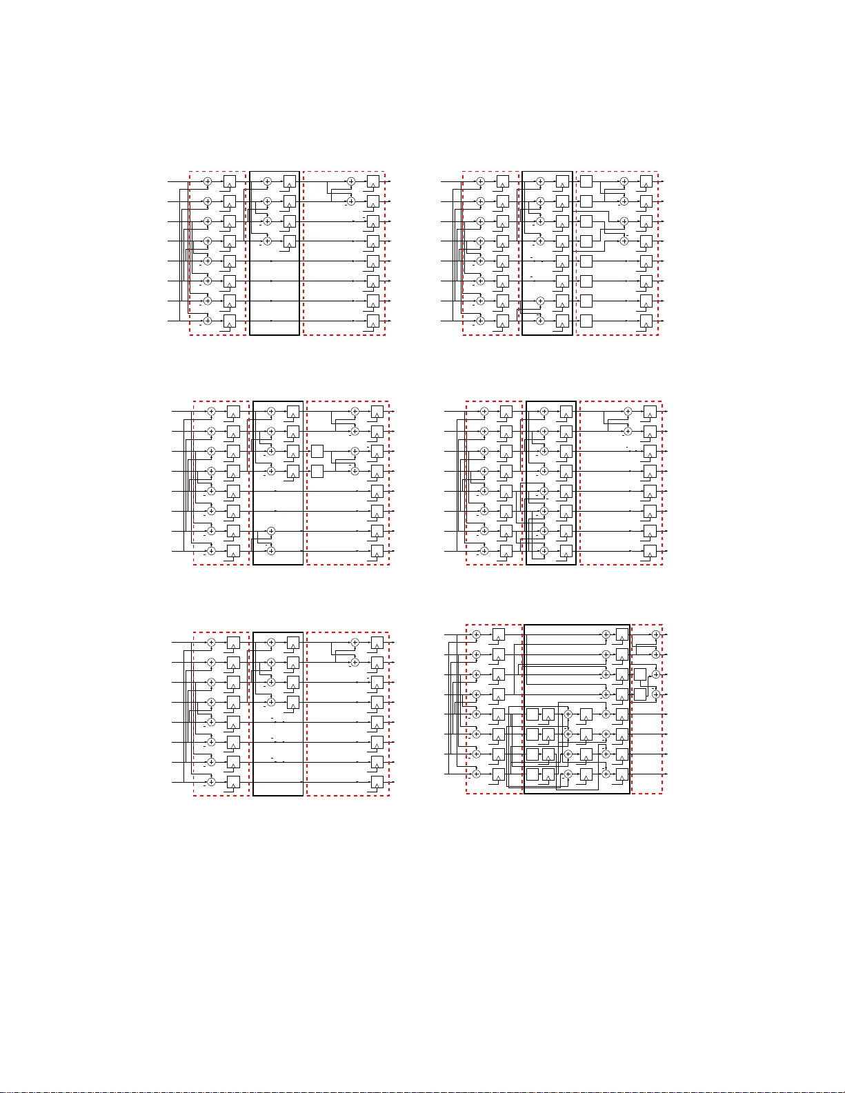
Improved 8-point Approximate DCT for Image and Video Compression Requiring Only 14 Additions
Video processing systems such as HEVC requiring low energy consumption needed for the multimedia market has lead to extensive development in fast algorithms for the efficient approximation of 2-D DCT transforms. The DCT is employed in a multitude of …
Authors: U. S. Potluri, A. Madanayake, R. J. Cintra
Impro v ed 8-p oin t Appro ximat e DCT for Image and Video Compressio n Requiring Only 1 4 Additions Uma Sadh vi P otluri ∗ Arjuna Madana y ak e ∗ Renato J. Cin tra † F´ abio M. Ba y er ‡ Sunera Kulasek era ∗ Amila Edirisuriy a ∗ Abstract Video process ing systems such as HEV C req uiring lo w energ y consumption needed for the m ultimedia market has lead to extensive development in fast a lgorithms for the efficient ap- proximation o f 2-D DCT transforms. The DCT is employ ed in a multit ude of compressio n standards due to its remark able energ y compa ction prop erties. Multiplier-free approximate DCT tra nsforms ha ve bee n prop osed that offer sup erior compress io n p erformance at very low circuit complexity . Such approximations can b e realized in dig ita l VLSI ha rdw are using addi- tions and subtractions only , leading to significant reductions in c hip area and power consumption compared to con ven tional DCTs and integer transfor ms. In this pa p er, we int ro duce a nov el 8- po in t DCT appr o ximation tha t req uir es only 1 4 a ddition o perations and no m ultiplications. The prop osed transform p ossesses low computational complexit y and is co mpared to state-of-the-art DCT approximations in terms of b oth algor ithm complexity and p eak signal-to- noise ra tio. The prop osed DCT approximation is a candidate for reco nfigurable v ideo standa rds such as HEVC. The prop osed transfor m and several other DCT approximations a re mapp ed to systolic-a rra y digital architectures and physically realized a s digital prototype c ir cuits using FPGA technology and mapp ed to 45 nm CMO S tec hnolog y . Keyw ords Approximate DCT, low-complexity a lgorithms, image compression, HEVC, lo w power consumption 1 In tro duction Recen t y ears hav e exp erienced a significant demand for h ig h dynamic range systems that op erate at high resolutions [1]. In particular, h igh-qualit y digital vid eo in multimedia devices [2] and video- ∗ Uma Sadhvi P otluri, Arjuna Madanay ake, S unera Kulasekera and Amila Ed ir isuriya are with the Department of Electrical and Computer Engineering, The Universit y of Akron, Akron, OH, USA (e-mail: arjuna@uakron.edu). † Renato J. Cin tra is with the Signal Processing Group , Departamento de Estat ´ ıstica, Universidade F ed eral de P ernambuco, Recife, PE, Brazi l ( e-mail : rjdsc@ieee.org). ‡ F´ abio M. Bay er is with th e Departamento de Estat ´ ıstica and Lab orat´ orio de Ciˆ encias Espaciais de Santa Maria (LACESM), Un iv ersidade F ederal d e Santa Maria , Santa Maria, R S, Brazil (e-mail: bay er@ufsm.br). 1 o v er-In ternet proto col net w orks [3] are prominen t areas wh ere such r equiremen ts are eviden t. Oth e r noticeable fields are geospatial r emote sens in g [4 ], tr a ffic cameras [5], automatic su rv eillance [1], homeland securit y [6], automotiv e industry [7], and multimedia wireless sensor net w orks [8 ], to name but a f ew. Often hardware capable of significan t throughp ut is necessary; as wel l as allo w able area-time complexit y [8]. In th is context, the discrete cosine transf o rm (DCT) [9 – 11] is an essentia l mathematical to ol in b oth image and vid e o cod ing [8, 11–15]. Ind ee d, the DCT was demonstrated to p ro vide go od energy compaction for natural images, wh ich can b e d esc rib ed by fi rst-order Mark o v signals [10, 1 1, 13]. Moreo v er, in man y situations, the DCT is a very close substitute for the Karh unen -Lo` ev e transform (KL T), which has optimal prop erties [9–11, 13, 14, 16]. As a result, the t w o-dimensional (2-D) v ersion of th e 8-p oin t DCT was adopted in s e veral imaging standards such as JPEG [17], MPEG-1 [18], MPEG-2 [19 ], H.261 [20], H.263 [21, 22], and H.264/A V C [23, 24]. Additionally , n ew compression s c h emes su ch as th e High Effi ci ency Vid e o Co ding (HEVC) em- plo ys DCT-lik e intege r transforms op erating at v arious blo c k sizes r a nging f rom 4 × 4 to 32 × 32 pixels [25 – 27]. The distinctiv e charac teristic of HEVC is its capabilit y of achieving high com- pression p erformance at app ro ximate ly half th e bit rate requ ir ed by H.264/A V C with same image qualit y [25–27]. Also HEV C was d e monstrated to b e esp ecial ly effectiv e for h ig h-resolution video applications [27]. Ho w ev er, HEV C p ossesses a significant computational complexit y in terms of arithmetic op erations [26 – 28]. In fact, HEV C can b e 2–4 times more computationally d emand- ing wh en compared to H.264/ A V C [26]. Ther efore, lo w complexity DCT-lik e approximat ions ma y b enefit fu ture v id eo co decs in clud ing emerging HEV C/H.265 systems. Sev eral efficien t algorithms were devel op ed and a noticeable literature is a v ailable [10 , 29 – 35]. Although fast algorithms can significan tly reduce the computational complexit y of computing the DCT, floating-p oin t op erations are still required [11]. Despite their accuracy , floating-p oin t op era- tions are exp ensiv e in terms of circuitry complexit y and p ow er consump tio n. T herefore, m in imizi ng the num b er of floating-p oin t op erations is a sought pr operty in a f a st algorithm. One wa y of cir- cum v enti ng this issue is by means of approximat e transf orm s. The aim of this pap er is tw o-fold. First, w e in tro duce a new DCT approximat ion that p os- sesses an extremely lo w arithmetic complexit y , r e quiring only 14 additions . T his no v el transform w as obtained b y means of solving a tailored optimization p r oblem aiming at minimizing the trans- form computational cost. Second, w e prop ose hardware imp le menta tions for sev eral 2-D 8-p oin t appro ximate DCT. The appro ximate DCT metho ds und er consideration are (i) th e pr oposed trans- form; (ii) th e 2008 Bouguezel-Ahmad-Sw am y (BAS) DCT app ro ximatio n [36]; (iii) the parametric transform for image compression [37]; (iv) the Cintra-B a ye r (CB) app ro ximate DCT b a sed on th e rounding-off fun ction [38 ]; (v) the mo dified CB appro ximate DCT [39]; and (vi) the DCT appr o xi- mation prop osed in [40] in the con text of b eamforming. All int ro duced implementat ions are sought to b e f ully parallel time-m ultiplexed 2-D architect ures for 8 × 8 d at a blo c ks. Add iti onally , the pr o- 2 p osed designs are based on successiv e calls of 1-D archite ctures taking adv antag e of the separabilit y prop ert y of the 2-D DCT kernel. Designs we re thorough ly assessed and compared. This pap er un folds as follo ws. In S ect ion 2, w e discuss the role of DCT-lik e fast algorithms for video CODECs while pr op osing some new p ossibilities for lo w-p o w er vid eo pro cessing wh ere rapid reconfiguration of th e hardware realization is p ossible. In Section 3, w e review s elected ap- pro ximate metho ds for DCT computation and describ e asso ciate fast algorithms in terms of matrix factorizat ions. Section 4 d eta ils the p roposed transform and its fast algorithm b ase d on matrix fac- torizatio ns. Section 5 discusses the computational complexit y of the approxi mate DCT tec hniques. P erformance measures are also quantified and ev aluated to assess the prop osed appr o xim ate DCT as well as the remaining selected ap p ro ximatio ns. In S ec tion 6 digital hardware arc hitectures for discussed algorithms are sup plied b oth for 1-D and 2-D analysis. Hardwa re resource consumptions using field programmable gate arra y (FPGA) an d CMOS 45 n m application-sp ecific integ rated circuit (ASIC) tec hnologies are tabulated. Conclusions and final remarks are in Section 7. 2 Reconfigurable DCT -lik e F ast A lgori thms in Video CODECs In curr e nt literature, seve ral appro ximate method s for the DCT calculation ha v e b een arc hiv ed [11]. While not computing the DCT exactly , such appro ximations can provide meaningful estimations at low-co mplexit y requirements. In particular, some DCT approximat ions can totall y eliminate the requirement for fl oa ting-p oin t op erations—all calculations are p erformed o v er a fixed-p oin t arithmetic framew ork. Prominen t 8-p oin t appr o x im ation-based tec hniques were prop osed in [14, 15, 36–44]. W orks addressin g 16-p o int DCT appro ximations are also archiv ed in literature [43, 45, 46]. In general, these approxima tion metho ds emplo y a transformation matrix wh ose elemen ts are defined o v er the set { 0 , ± 1 / 2 , ± 1 , ± 2 } . Th is implies n ull m ultiplicativ e complexit y , b ecause the required op eratio ns can b e implemen ted exclusiv ely by means of b inary ad d itio ns and sh ift op era- tions. Such DCT ap p ro ximatio ns can pro vide lo w-cost and low-pow er d esigns and effectiv ely r eplac e the exact DCT and other DCT-like transforms . I ndeed, the p erformance c haracteristics of the lo w complexit y DCT appr o ximations ap p ear similar to the exact DCT, while th ei r asso ciate h ardw are implemen tations are economical b ecause of th e absence of m ultipliers [14, 15, 36 – 43, 43 – 46]. As a consequence, some prosp ectiv e app lic ations of DCT approximati ons are foun d in real-time vid eo transmission and pro cessing. Emerging vid eo standards such as HEV C pro vide for reconfigurable op eration on-the-fly wh ic h mak es the av ailabilit y of an ens emble of fast algorithms and digital VLSI arc hitectures a v aluable asset for low-energy high-p erformance em b edded systems. F or certain applications, lo w circuit complexit y and/or p o we r consumption is the d riving factor, while for certain other app lic ations, highest p ict ure qualit y f o r reasonably low p o w er consumption and/or complexit y ma y b e more imp ortan t. In emerging systems, it may b e p ossible to s witc h mo dus op er andi based on the de- manded picture qualit y vs a v ai lable energy in the device. Su c h feature wo uld b e in v aluable in high 3 qualit y sm art video devices demand ing extended battery life. T h us, th e a v ail abilit y of a suite of fast algorithms and implemen tation libr aries for several efficien t DCT app ro ximatio n algorithms ma y b e a welc oming con tribution. F or example, in a futur e HEVC system, it may b e p ossible to reconfigur e the DCT engine to use a higher complexity DCT app ro ximatio n wh ic h offers b etter signal-to-noise r at io (SNR) when the master device is p o wered b y a remote p o we r sour ce , and then hav e the device seamlessly switc h in to a lo w complexit y fast DCT algorithm w hen the battery storage f alls b elo w a certain th reshold, for example [47 ]. Alternativ ely , the CO DEC ma y b e reconfigured in real-time to switch b et w een differen t DCT approximat ions offering v arying picture qualit y and p o we r consumptions dep ending on the measured SNR of the incoming video stream, wh ic h would b e con ten t sp ecific and v ery difficult to predict without resorting to real-time video metrics [48]. F u r thermore, another p ossible app lic ation f o r a su it e of DCT appro ximation algorithms in the ligh t of reconfigur able video co decs is the in telligen t in tra-frame fast reconfiguration of th e DCT core to tak e in to accoun t certain lo ca l frame information and measured S NR metrics. F or example, certain parts of a frame can d emand b etter picture qualit y (foreground , sa y) wh en compared to relativ ely u nimp ortan t part of the frame (bac kground , say) [48]. In suc h a case, it may b e p ossible to switch DCT appro ximations algorithms on an intra frame basis to tak e into accoun t the v arying demands f or picture clarit y within a frame as we ll as th e a v aila bilit y of reconfigurable logic based digital DCT engines that sup port fast r ec onfigur a tion in real-time. 3 Review of Appro ximate DCT M et ho ds In this s e ction, w e review the m at hematical description of the selected 8-p oin t DCT app ro ximatio ns. All discussed metho ds h er e consist of a tr an s formati on matrix that can b e put in the follo wing format: [diagonal matrix] × [lo w-complexit y matrix] . The diagonal matrix u sually con tains irrational n umb ers in th e form 1 / √ m , where m is a small p ositiv e in teger. In principle, the irr a tional num b ers required in the diagonal matrix would re- quire an incr eased compu tational complexit y . Ho w ev er, in the con text of image compr ession, the diagonal m atrix can simply b e absorb ed into the qu an tiza tion step of JPEG-like compression pr o- cedures [15, 36 – 39, 42]. Therefore, in this case, the complexity of the appr o ximat ion is b ounded b y the complexit y of the lo w-complexit y matrix. Since the entrie s of the lo w complexit y matrix comprise only p o w ers of t wo in { 0 , ± 1 / 2 , ± 1 , ± 2 } , null multiplica tiv e complexit y . is ac hiev ed. In the next sub sect ions, we detail these metho ds in terms of its transformation matrices and the asso cia ted fast algorithms obtained b y matrix f ac torization tec hniqu es. All derive d fast algorithms emplo y sparse matrices w hose elemen ts are the ab o v e-men tioned p o w ers of t w o. 4 3.1 Bouguezel-Ahmad-Sw amy A ppro xima te D C T In [36], a lo w-complexit y appr o ximate wa s in tro duced b y Bouguezel et al. W e refer to this ap- pro ximate DCT as BAS-2008 approximat ion. The BAS-2008 app r o ximat ion C 1 has th e follo wing mathematical structure: C 1 = D 1 · T 1 = D 1 · 1 1 1 1 1 1 1 1 1 1 0 0 0 0 − 1 − 1 1 1 2 − 1 2 − 1 − 1 − 1 2 1 2 1 0 0 − 1 0 0 1 0 0 1 − 1 − 1 1 1 − 1 − 1 1 1 − 1 0 0 0 0 1 − 1 1 2 − 1 1 − 1 2 − 1 2 1 − 1 1 2 0 0 0 − 1 1 0 0 0 , where D 1 = diag 1 √ 8 , 1 √ 4 , 1 √ 5 , 1 √ 2 , 1 √ 8 , 1 √ 4 , 1 √ 5 , 1 √ 2 . A fast algorithm for matrix T 1 can b e d eriv ed b y m e ans of m atrix factorizatio n. In deed, T 1 can b e written as a p rod u ct of th r ee sparse matrices ha ving { 0 , ± 1 / 2 , ± 1 } elemen ts as shown b elo w [36]: T 1 = A 3 · A 2 · A 1 , where A 1 = h I 4 ¯ I 4 ¯ I 4 − I 4 i , A 2 = 1 0 0 1 0 0 0 0 0 0 0 0 0 0 1 1 0 1 1 0 0 0 0 0 0 0 0 0 0 − 1 0 0 0 1 − 1 0 0 0 0 0 0 0 0 0 0 0 − 1 1 1 0 0 − 1 0 0 0 0 0 0 0 0 − 1 0 0 0 , A 3 = 1 0 1 0 0 0 0 0 0 1 0 0 0 0 0 0 0 0 0 0 1 2 0 1 0 0 0 0 1 0 0 0 0 1 0 − 1 0 0 0 0 0 0 0 0 0 0 1 0 0 0 0 0 0 − 1 0 1 2 0 0 0 0 0 0 0 0 1 . Matrices I n and ¯ I n denote the iden tit y and counte r-identit y matrices of ord er n , r e sp ectiv ely . I t is recognizable that matrix A 1 is the w ell-kno wn decimation-in-frequency structure present in sev eral fast algorithms [11]. 3.2 P arametric T ransform Prop osed in 2011 by Bouguezel-Ahmad-Sw am y [37], the p arame tric transform is an 8-p oin t orthog- onal transform cont aining a single p arameter a in its transformation m atrix C ( a ) . In this wo rk, w e refer to this metho d as the BAS-2011 transf o rm. It is give n as follo ws: C ( a ) = D ( a ) · T ( a ) = D ( a ) · 1 1 1 1 1 1 1 1 1 1 0 0 0 0 − 1 − 1 1 a − a − 1 − 1 − a a 1 0 0 1 0 0 − 1 0 0 1 − 1 − 1 1 1 − 1 − 1 1 0 0 0 1 − 1 0 0 0 1 − 1 0 0 0 0 1 − 1 a − 1 1 − a − a 1 − 1 a , where D ( a ) = diag 1 √ 8 , 1 2 , 1 √ 4+4 a 2 , 1 √ 2 , 1 √ 8 , 1 √ 2 , 1 2 , 1 √ 4+4 a 2 . Usually th e parameter a is selected as a small inte ger in order to minimize the complexit y of T ( a ) . In [37], suggested v alues are a ∈ { 0 , 1 / 2 , 1 } . The v al ue a = 1 / 2 will not b e considered in our analyses b ecause in h ard w are it represent s a right -shift which may incur in computational errors. Another p ossible v al ue that furnish es a low-c omplexit y , error-free transform is a = 2. The matrix factorization of T ( a ) that 5 leads to its fast algorithm is [37]: T ( a ) = P 1 · Q ( a ) · A 4 · A 1 , wh er e Q ( a ) = diag h 1 1 1 − 1 i , h a 1 − 1 a i , I 4 , and A 4 = diag 1 0 0 1 0 1 1 0 0 1 − 1 0 1 0 0 − 1 , I 2 , h 1 1 − 1 1 i . Matrix P 1 p erforms the simp le p erm utation (1)(2 5 6 4 8 7)(3), where cyclic n otation is emplo y ed [49 , p. 77]. This is a compact notation to denote p erm utation. In this particular case, it means that comp onen t indices are p erm uted according to 2 → 5 → 6 → 4 → 8 → 7 → 2. Indices 1 and 3 are u n c hanged. Therefore, P 1 represent s no computational complexit y . 3.3 CB-2011 Approxim ation By means of jud ici ously roun ding-off the elemen ts of the exact DCT matrix, a DCT approxi mation w as obtained and describ ed in [38]. The r esulting 8-p oin t appr o ximation m atrix is orthogonal and con tains only elements in { 0 , ± 1 } . C le arly , it p ossesses v ery lo w arithmetic complexit y [38]. The matrix derive d transform a tion matrix C 2 is giv en by: C 2 = D 2 · T 2 = D 2 · 1 1 1 1 1 1 1 1 1 1 1 0 0 − 1 − 1 − 1 1 0 0 − 1 − 1 0 0 1 1 0 − 1 − 1 1 1 0 − 1 1 − 1 − 1 1 1 − 1 − 1 1 1 − 1 0 1 − 1 0 1 − 1 0 − 1 1 0 0 1 − 1 0 0 − 1 1 − 1 1 − 1 1 0 , where D 2 = diag 1 √ 8 , 1 √ 6 , 1 2 , 1 √ 6 , 1 √ 8 , 1 √ 6 , 1 2 , 1 √ 6 . An efficien t factorization for the fast algo- rithm for T 2 w as prop osed in [38] as describ ed b elo w: T 2 = P 2 · A 6 · A 5 · A 1 , where A 5 = diag 1 0 0 1 0 1 1 0 0 1 − 1 0 1 0 0 − 1 , − 1 1 − 1 0 − 1 − 1 0 1 1 0 − 1 1 0 1 1 1 and A 6 = diag h 1 1 1 − 1 i , − 1 , I 5 . Matrix P 2 corresp onds to the follo wing p ermutat ion: (1)(2 5 8)(3 7 6 4). 3.4 Mo dified CB - 2011 A ppro xima tion The transform p rop o sed in [39 ] is obtained by r eplac ing elemen ts of the CB-2011 matrix with zeros. The resulting matrix is giv en by: C 3 = D 3 · T 3 = D 3 · 1 1 1 1 1 1 1 1 1 0 0 0 0 0 0 − 1 1 0 0 − 1 − 1 0 0 1 0 0 − 1 0 0 1 0 0 1 − 1 − 1 1 1 − 1 − 1 1 0 − 1 0 0 0 0 1 0 0 − 1 1 0 0 1 − 1 0 0 0 0 − 1 1 0 0 0 , where D 3 = diag 1 √ 8 , 1 √ 2 , 1 2 , 1 √ 2 , 1 √ 8 , 1 √ 2 , 1 2 , 1 √ 2 . Matrix T 3 can b e factorized in to T 3 = P 2 · A 6 · A 7 · A 1 , where A 7 = diag 1 0 0 1 0 1 1 0 0 1 − 1 0 1 0 0 − 1 , − I 3 , 1 . This p artic ular DCT approxima tion has the distinction of requirin g only 14 additions for its computation [39]. 6 3.5 Appro ximate DCT in [40] In [40], a DCT app ro ximatio n tailored for a p artic ular radio-frequency (RF) application was ob- tained in accordance with an exhaustiv e computational searc h. Th is transformation is given by C 4 = D 4 · T 4 = D 4 · 1 1 1 1 1 1 1 1 2 1 1 0 0 − 1 − 1 − 2 2 1 − 1 − 2 − 2 − 1 1 2 1 0 − 2 − 1 1 2 0 − 1 1 − 1 − 1 1 1 − 1 − 1 1 1 − 2 0 1 − 1 0 2 − 1 1 − 2 2 − 1 − 1 2 − 2 1 0 − 1 1 − 2 2 − 1 1 0 , where D 4 = 1 2 · d ia g 1 √ 2 , 1 √ 3 , 1 √ 5 , 1 √ 3 , 1 √ 2 , 1 √ 3 , 1 √ 5 , 1 √ 3 . The fast algorithm for its compu ta- tion consists of the follo wing matrix factorization: T 4 = P 3 · A 9 · A 8 · A 1 , wh er e A 9 = diag h 1 1 1 − 1 i , h 1 2 − 2 1 i , I 4 , A 8 = d ia g 1 0 0 1 0 1 1 0 0 1 − 1 0 1 0 0 − 1 , 0 1 1 2 − 1 − 2 0 1 1 0 − 2 1 − 2 1 − 1 0 , and matrix P 3 denotes the p erm utation (1)(2 5)(3)(4 7 6)(8). 4 Prop osed T ransform W e aim at deriving a n o vel lo w-complexit y approximate DCT. F or such end, w e prop ose a searc h o v er the 8 × 8 matrix space in ord er to find candidate matrices that p ossess low computation cost. Let us defi ne the cost of a tr a nsf orm a tion matrix as the num b er of arithmetic op erations r equired for its compu ta tion. One wa y to guarant ee go o d candidates is to restrict the search to m atrices whose en tries do not require multiplicat ion op erations. T hus w e hav e the follo wing optimization problem: T ∗ = arg min T cost( T ) , (1) where T ∗ is the sought matrix and cost( T ) r etur ns the arithmetic complexit y of T . Additionally , the follo wing constrain ts w ere adopted: 1. Elemen ts of matrix T m ust b e in { 0 , ± 1 , ± 2 } to en sure that resulting multiplica tiv e complexit y is null; 2. W e imp ose the follo wing form for matrix T : T = a 3 a 3 a 3 a 3 a 3 a 3 a 3 a 3 a 0 a 2 a 4 a 6 − a 6 − a 4 − a 2 − a 0 a 1 a 5 − a 5 − a 1 − a 1 − a 5 a 5 a 1 a 2 − a 6 − a 0 − a 4 a 4 a 0 a 6 − a 2 a 3 − a 3 − a 3 a 3 a 3 − a 3 − a 3 a 3 a 4 − a 0 a 6 a 2 − a 2 − a 6 a 0 − a 4 a 5 − a 1 a 1 − a 5 − a 5 a 1 − a 1 a 5 a 6 − a 4 a 2 − a 0 a 0 − a 2 a 4 − a 6 , where a i ∈ { 0 , 1 , 2 } , for i = 0 , 1 . . . , 6; 3. All ro ws of T are n o n-null; 7 4. Matrix T · T ⊤ m ust b e a diagonal matrix to ensure orthogonalit y of th e resulting ap p ro xima- tion [50]. Constrain t 2) is required to preserve the DCT-like matrix structur e. W e recall that the exact 8-p oin t DCT matrix is give n by [35]: C = 1 2 · γ 3 γ 3 γ 3 γ 3 γ 3 γ 3 γ 3 γ 3 γ 0 γ 2 γ 4 γ 6 − γ 6 − γ 4 − γ 2 − γ 0 γ 1 γ 5 − γ 5 − γ 1 − γ 1 − γ 5 γ 5 γ 1 γ 2 − γ 6 − γ 0 − γ 4 γ 4 γ 0 γ 6 − γ 2 γ 3 − γ 3 − γ 3 γ 3 γ 3 − γ 3 − γ 3 γ 3 γ 4 − γ 0 γ 6 γ 2 − γ 2 − γ 6 γ 0 − γ 4 γ 5 − γ 1 γ 1 − γ 5 − γ 5 γ 1 − γ 1 γ 5 γ 6 − γ 4 γ 2 − γ 0 γ 0 − γ 2 γ 4 − γ 6 , where γ k = cos(2 π ( k + 1) / 32), k = 0 , 1 , . . . , 6. Ab o v e optimization p roblem is algebraically in tractable. T h erefore w e resorted to exh au s ti ve computational searc h. As a r esult, eight candidate m atrices were found, includ in g the transform matrix pr o p osed in [39]. Am on g these minimal cost matrices, we separated the matrix th a t presen ts the b est p erformance in terms of image qualit y of compressed images according th e JPEG-like tec hnique employ ed in [36–39, 41 – 44], and b riefly reviewe d in n ext Section 5. An imp ortan t parameter in the image compression routine is the num b er of retained coefficient s in th e transform domain. In sev eral applications, the num b er of retained co efficien ts is v ery lo w. F or instance, considering 8 × 8 image blo c ks, (i) in image compr ession using supp ort vec tor mac hine, only the fi rst 8–16 co efficien ts w ere considered [5 1]; (ii) Ma ndyam et al. prop osed a metho d for image reconstru ct ion based on only three co effic ient s; and Bouguezel et al. employ ed only 10 DCT co efficien ts when assessing image compr essio n metho ds [41 , 42]. Retaining a v ery small n umb er of co efficien ts is also common f or other image b loc k sizes. In h ig h sp eed face recognition applications, Pan et al. demonstrated th at just 0.34%–2 4.26% out of 92 × 112 DCT co efficien ts are sufficien t [52, 53]. Therefore, as a compromise, w e adopted the n umber of retained coefficient s equal to 10, as suggested in the exp erimen ts b y Bouguezel et al. [41, 42]. The solution of (1) is the follo wing DCT ap p ro ximatio n: C ∗ = D ∗ · T ∗ = D ∗ · 1 1 1 1 1 1 1 1 0 1 0 0 0 0 − 1 0 1 0 0 − 1 − 1 0 0 1 1 0 0 0 0 0 0 − 1 1 − 1 − 1 1 1 − 1 − 1 1 0 0 0 1 − 1 0 0 0 0 − 1 1 0 0 1 − 1 0 0 0 1 0 0 − 1 0 0 , where D ∗ = diag 1 √ 8 , 1 √ 2 , 1 2 , 1 √ 2 , 1 √ 8 , 1 √ 2 , 1 2 , 1 √ 2 . Matrix T ∗ has en tries in { 0 , ± 1 } and it can b e giv en a sp a rse fact orization according t o: T ∗ = P 4 · A 12 · A 11 · A 1 , where A 11 = diag 1 0 0 1 0 1 1 0 0 1 − 1 0 1 0 0 − 1 , I 4 , A 12 = diag h 1 1 1 − 1 i , − 1 , I 5 , and P 4 is the p erm utation (1)(2 5 6 8 4 3 7). 8 5 Computational Complexit y and P erformance A nalysis The p erformance of the DCT appr o xim ations is often a tr ad e-off b et w een accuracy and computa- tional complexit y of a giv en algorithm [11]. In this section, we assess the computational complexit y of the discussed m etho ds and ob jectiv ely compare th em. Additionally , w e separate sev eral p erfor- mance measures to quantify ho w “clo se” eac h approxi mation are; and to ev aluate their p erformance as image compression to ol. 5.1 Arithmetic Complexit y W e adopt the arithmetic complexit y as fi gure of mer it f o r estimating the computational com- plexit y . The arithmetic complexit y consists of the num b er of elemen tary arithm e tic op erations (additions/subtractions, m ultiplications/divisions, and bit-shift op erations) requ ired to compu te a giv en tran s formatio n. In other words, in all cases, w e fo cus our atten tion to th e low-co mplexity matrices: T 1 , T ( a ) , T 2 , T 3 , T 4 , and the prop osed matrix T ∗ . F or instance, in the con text of image and video compression, the complexit y of the diagonal m a trix can b e absorb ed into the quan tiza- tion step [15, 36–39, 42]; therefore the d iagonal matrix do es not con tribu te to w ards an in crea se of the arithmetic complexit y [38, 39]. Because al l considered DCT appro ximations ha v e null m ultiplicativ e complexit y , we resort to comparing them in term s of their arithmetic complexit y assessed by the num b er of addi- tions/subtractions and bit-shift op erations. T able 1 displa ys the obtained complexities. W e also include the complexit y of the exact DCT calculated (i) directly f r om d e fin iti on [10 ] and (ii) accord- ing to Arai f a st algorithm for the exact DCT [33]. W e d eriv ed a fast algorithm for the p roposed transform, employing only 14 additions . T his is th e s ame very lo w-complexit y exhibited by the Mo dified CB-2011 app ro ximatio n [39]. T o the b est of our kno wledge these are DCT ap p ro ximatio ns offering th e lo we st arithmetic complexit y in literature. 5.2 Comparativ e Performance W e emp lo yed three classes of assessment to ols: (i) matrix p ro ximit y metrics with r esp ect to the exact DCT m at rix; (ii) transf orm-rela ted measures; and (iii) image qualit y measures in image compression. F or the first class of measures, we adopted the total error energy [38] and the mean- square error (MSE ) [11, 13]. F or transform p erformance ev aluation, we selecte d the transf o rm co ding gain ( C g ) [11, 13] and the transform efficiency ( η ) [11, 54]. Finally , for image qualit y assessment w e emplo y ed the p eak SNR (PS NR) [55, 56 ] and the un iv ersal qualit y index (UQI) [57]. Next subsections furnish a brief description of eac h of these m ea sures. 9 T able 1: Arithmetic complexit y an alysis Metho d Mult Add Shifts T otal Exact DCT (Definition) [10] 64 56 0 120 Arai algorithm (exact) [33] 5 29 0 34 BAS-2008 [36] 0 18 2 20 BAS-2011 [37] with a = 0 0 16 0 16 BAS-2011 [37] with a = 1 0 18 0 18 BAS-2011 [37] with a = 2 0 18 2 20 CB-2011 [38] 0 22 0 22 Mo dified CB-2011 [39] 0 14 0 14 Appro ximate DCT in [40] 0 24 6 30 Prop osed transform 0 14 0 14 5.2.1 Matrix Pro ximit y Metrics Let ˆ C b e an approximate DCT matrix and C b e the exact DCT matrix. The total error energy is an energy-based measure f o r quantifying the “distance” b et wee n C and ˆ C . It is describ ed as follo ws [38]. Let H m ( ω ; T ) is th e transfer function of the m -th ro w of a giv en matrix T as sho wn b elo w: H m ( ω ; T ) = 8 X n =1 t m,n exp − ( n − 1) ω , m = 1 , 2 , . . . , 8 , where = √ − 1 and t m,n is the ( m, n )-th elemen t of T . T hen the row-wise err o r energy related to the difference b et w een C and ˆ C is furnish ed b y: D m ( ω ; ˆ C ) , H m ( ω ; C − ˆ C ) 2 , m = 1 , 2 , . . . , 8 . W e note that, for eac h row m at any angular frequency ω ∈ [0 , π ] in radians p er s amp le, D m ( ω ; C − ˆ C ) expression quanti fies ho w d iscrepan t a giv en ap p ro ximatio n matrix ˆ C is fr o m the matrix C . In this w a y , a total error energy d eparting from the exact DCT can b e obtained b y [38]: ǫ = 8 X m =1 Z π 0 D m ( ω ; ˆ C ) d ω. Ab o v e in tegral can b e computed b y numerical quadr a ture metho ds [58 ]. F or the MS E ev aluation, w e assume that the inp ut signal is a first-order Gaussian Mark o v pro cess with zero-mean, unit v ariance, and correlation equal to 0.95 [11, 13]. T ypically images satisfy these requir emen ts [11]. Th e MSE is m a thematically detailed in [11, 13] and shou ld b e minimized 10 to main tain the compatibilit y b et w een the approxima tion and the exact DCT outputs [11]. 5.2.2 T ransform-relate d Measures The transform co ding gain is an imp ortan t fi gure of merit to ev aluate the co ding efficiency of a giv en transform as a data compression to ol. Its mathematical descrip tio n can b e foun d in [11, 13]. Another measure to ev aluat e the transform co ding gain is the transform efficiency [11, 54]. The optimal KL T con v erts signals in to completel y un co rrelated co e fficient s that has tran s form efficiency equal to 100, whereas the DCT-I I ac hiev es a tr a nsf orm efficiency of 93.9911 for Marko vian data at correlation co efficie nt of 0.95 [11]. 5.2.3 Image Quality Measures in JPEG-lik e Compression F or qualit y analysis, images were sub mitt ed to a JP EG-l ike tec hnique for image compression. The resulting compressed images are th en assessed for image degradation in comparison to the original input image. Thus, 2-D versions of the discussed metho ds are required. An 8 × 8 image blo c k A has its 2-D transform mathematically expressed by [59]: T · A · T ⊤ , (2) where T is a considered transformation. Input images were divided into 8 × 8 sub -bloc ks, wh ic h w ere submitted to the 2-D transform s. F or eac h blo c k, this compu ta tion furnish ed 64 co efficien ts in th e appro ximate transform domain f o r a p artic ular transformation. According to the standard zigzag sequence [60 ], only the 2 ≤ r ≤ 20 initial co efficie nts in eac h blo c k were r et ained and employ ed for image reconstruction [38]. This range of r corresp onds to high compression. All the r emainin g co e fficient s were set to zero. Th e in v erse pro cedure w as then applied to reconstruct the pro cessed image. Subsequ ently , reco ve red images had th eir PSNR [55] and UQI [57] ev aluate d. The PSNR is a standard qualit y metric in the image p rocessing literature [56], and the UQI is regarded as a more sophisticate to ol for qualit y assessmen t, wh ic h tak es into consideration structural similarities b et w een images under analysis [38, 57]. This metho dology was employ ed in [14], sup ported in [36, 37, 41–43], and extended in [38, 39]. Ho w ev er, in contrast to the JPEG-lik e exp eriments d esc rib ed in [36, 37, 41–43], the extended exp erimen ts considered in [38, 39] adopted the av erag e image qualit y measure from a collec tion of represent ativ e images instead of resorting to measurement s obtained from single particular images. This approac h is less prone to v ariance effects and fortuitous inp ut d at a, b eing more robust [61]. F or the ab o v e pro cedure, w e considered a set of 45 8-bit greyscale 512 × 512 standard images ob tained from a public image bank [62]. 11 T able 2: Accuracy measures of discussed metho ds Metho d ǫ MSE ( × 10 − 2 ) C g η PSNR UQI Exact DCT 0.000 0.000 8.826 93.991 28.33 6 0.7 33 BAS-2008 [36] 5.929 2.378 8.120 86.863 27.24 5 0.6 86 BAS-2011 [37] with a = 0 26.864 7.104 7.912 85.642 26.91 8 0.6 69 BAS-2011 [37] with a = 1 26.864 7.102 7.913 85.380 26.90 2 0.6 68 BAS-2011 [37] with a = 2 27.922 7.832 7.763 84.766 26.29 9 0.6 29 CB-2011 [38] 1.794 0.980 8.184 87.432 27.36 9 0.6 97 Mo dified CB-2011 [39] 8.659 5.939 7.333 80.897 25.22 4 0.5 63 Appro ximate DCT in [40] 0.870 0.621 8.344 88.059 27.56 7 0.7 01 Prop osed trans f o rm 11.313 7.899 7.333 80.89 7 25 .726 0.586 5.3 P erformance Results Figure 1 presents the resulting av erage PSNR and a ve rage UQI absolute p ercenta ge error (APE) relativ e to the DCT, for r = 2 , 3 , . . . , 20, i.e., for h ig h compr essio n ratios [38]. Th e prop osed transform could outp erform the Mo dified CB-2011 approximati on for 10 ≤ r ≤ 15, i.e. , when 84.38% to 76.5 6% of the DCT co efficien ts are discarded. Su c h h ig h compression ratios are emplo y ed in sev eral applications [41 , 51 – 53, 63]. T able 2 sho ws the p erformance measures for th e considered transforms . Averag e P S NR and UQI measures are pr ese nted for all considered images at a selected h igh compression ratio r = 10. The appro ximate transform prop osed in [40] could outp erform r ema ining metho ds in term s of pro ximity measures (total energy err o r and MSE) when compared to the exact DCT. It also f urnished go o d image qualit y measure results (av erag e PSNR = 27 . 567 dB ). Ho w ev er, at the same time, it is the most exp ensiv e app ro ximatio n measured b y its computational cost as shown in T able 1. On the other hand, the tran s forms with lo w est arithmetic complexities are the Mo dified CB-2011 appro ximation and new p rop osed tr an s form, b oth requiring only 14 additions. Th e new transform could ou tp erform the Mo dified CB-2011 appr oximati on as an image compression to ol as indicated b y the PSNR and UQI v alues. A qu ali tativ e comparison b ased on th e resulting compressed image Lena [62] obtained from th e ab o v e describ e pr o cedure for r = 10 is sh o w n in Fig. 2. Fig. 1 and T able 2 illustrate the usual trade-off b et we en computational complexit y and p er- formance. F or instance, although BAS-2011 (for a = 0) could yield a b etter PSNR figure when compared with the prop osed algorithm, it is computationally more demanding (ab out 14.3% m ore op eratio ns) and its co ding gain and transf o rm efficiency are impr ov ed in only 7.9% and 5%, resp ec- tiv ely . I n cont rast, th e prop osed algorithm requires only 14 additions, which can lead to smaller, faster and more energy efficien t circuitry designs. In the next section, w e offer a compreh e nsive hardware analysis and comparison of the discussed algorithms with several implemen tation sp ecific figures of merit. 12 2 4 6 8 10 12 14 16 18 20 24 26 28 30 r PSNR (dB) DCT B AS−2008 [36] B AS−2011 with a=0 [37] CB−2011 [38] Approximate DCT in [40] Modified CB−2011 [39] Proposed (a) A v erage PSNR 2 4 6 8 10 12 14 16 18 20 0.1 0.2 0.3 0.4 0.5 r APE (UQI) B AS−2008 [36] B AS−2011 with a=0 [37] CB−2011 [38] Approximate DCT in [40] Modified CB−2011 [39] Proposed (b) A v erage UQI absolute p ercen tage error relativ e to the DCT Figure 1: Image qualit y m ea sures for seve ral compression ratios. 13 (a) BA S -2008 (b) BAS-2011 ( a = 0) (c) CB-2011 (d) Mod ified CB-2011 [39 ] (e) Approximate DCT in [40] (f ) Prop osed transform Figure 2: Compressed Lena image using sev eral DCT approxima tions. Compression r a tio is 84 . 375% ( r = 10). 14 0.0 0.5 1.0 1.5 2.0 2.5 3.0 3.5 4.0 4.5 5.0 35 40 45 50 bits/frame PSNR (dB) DCT Proposed Figure 3: RD curves for ‘Bask etballP ass’ test sequence. W e also notice that although the pro ximit y of the exact DCT—as measured by the MS E—is a go o d c haracteristic, it is not the defining prop ert y of a go od DCT app r o ximat ion, sp ecially in image compression applications. A vivid example of this—seemingly counter-in tuitiv e p h enomenon—is the BAS ser ies of DCT appr o x im ation. S uc h app ro ximatio ns p ossess comparative ly large v alues of pro ximit y m e asures (e.g., MSE) w hen compared with the exact DCT matrix. Neve rtheless, th ey exhibit very go o d p erformance in image compression application. Results d ispla y ed in T able I I illustrate this b eha vior. 5.4 Implemen tation in Real T ime Video Compression Softw are The pr o p osed approxima te DCT transf o rm w as emb edded into an op en sour ce HEVC standard reference soft wa re [64] in ord er to assess its p erformance in real time video co ding. The original in teger transform prescrib ed in the s elected HEVC reference soft wa re is a scaled appro ximation of Chen DCT algorithm [65], w hic h emplo ys 26 additions. F or comparison, the p roposed approximate DCT requires only 14 additions. Both algorithms were ev aluated for their effect on the ov erall p erformance of the enco ding pro cess by obtaining rate-distortion (RD) cur ves for standard video sequences. Th e curves were obtained by v arying the quantiz ation p oin t (QP) from 0 to 50 and obtaining the PS NR of the p roposed appro ximate transform with r eference to the Chen DCT implemen tation, wh ic h is already implemen ted in the reference s o ftw are, along with the bits/frame of the enco ded video. The PS NR computation w as p erformed by taking the a ve rage PSNR obtained from the three channels YCb Cr of the color image, as s ugg ested in [66, p. 55]. Fig. 3 depicts the obtained RD curves f or the ‘Bask etballP ass’ test sequence. Fig. 4 sh o w s p artic ular 416 × 240 frames for QP ∈ { 0 , 32 , 50 } when the prop osed appr o ximat e DCT and the C hen DCT are considered. The RD curves r eveal s that the difference in the rate p oin ts of Chen DCT and pr oposed ap- 15 (a) Chen DCT (QP = 0) (b) Prop os ed DCT (QP = 0) (c) Chen DCT (QP = 32) (d) Prop osed DCT (QP = 32) (e) Chen DCT (QP = 50) (f ) Prop osed DCT (QP = 50) Figure 4: Selected f rames fr om ‘Bask etballP ass’ test vid e o cod ed by means of the Chen DCT and the prop osed DCT app r o ximat ion for QP = 0 (a-b), QP = 32 (c-d), and QP = 50 (e-f ). 16 pro ximation is negligible. In fact, the mean absolute difference was 0.1234 dB, whic h is v ery lo w. Moreo v er, the f rames show that b oth enco ded video streams usin g the ab o v e t wo DCT trans- forms are almost identical . F or eac h QP v alue, the PS NR v alues b et w een the resulting frames were 82.51 dB, 42.26 dB, and 36.38 dB, resp ectiv ely . These v ery high PSNR v alues confirm the adequacy of the prop osed sc heme. 6 Digital Arc hitectures and Realizations In this section we pr opose arc hitectures for the detailed 1-D and 2-D app ro ximate 8-p oin t DCT. W e aim at physic ally implementing (2) for v arious transformation matrices. Introd uced arc hitectures w ere submitted to (i) Xilinx FPGA implementat ions and (ii) CMOS 45 nm app lica tion sp ecific in tegrated circuit (ASIC) implementat ion up to the synt hesis lev el. This section explores the hardware utilization of the discuss ed algorithms while providing a comparison with the pr o p osed n o vel DCT appro ximation algorithm and its fast algorithm realiza- tion. Our ob j ec tiv e her e is to offer digital realizations together with measured or sim ulated metrics of hardwa re resources so th a t b etter decisions on the c hoice of a p artic ular fast algorithm and its implemen tation can b e r ea c hed. 6.1 Prop osed A rc hitectures W e prop ose digital computer arc hitectures that are cus tom d esigned for the real-time implemen ta- tion of the fast algorithms describ ed in Section 3. The prop osed arc hitectures emplo ys t w o parallel realizatio ns of DCT appr oximati on b loc ks, as sh o wn in Fig. 5. The 1-D appr o ximate DCT blo c ks (Fig. 5 ) implemen t a particular fast algorithm chosen from the collect ion describ ed earlier in the p aper. The first instan tiation of the DCT blo c k f u rnishes a ro w-wise transform computation of the inp ut image, while the second imp leme ntat ion f urnishes a column-wise trans f ormati on of the in termediate r esult. T he row- and column-wise tr a nsf orm s can b e an y of the DCT approximat ions d eta iled in the pap er. In other w ords, there is no restriction for b oth ro w- and column-wise transforms to b e the same. Ho we ve r, for sim p lic it y , we adopted iden tical transforms f or b oth s te ps. Bet w een the approxima te DCT blo c ks a real-time row-paralle l tr an s position buffer circuit is required. S uc h blo c k ensures d a ta ord ering for conv erting the ro w-transformed data from the fi rst DCT appr o x im ation circuit to a tr a nsp osed format as required by the column transform circuit. The transp osition bu ffer b loc k is d eta iled in Fig. 6. The digital architect ures of the discussed appr oximate DCT algorithms we re giv en h a rd ware signal flo w diagrams as listed b elo w: 1. Prop osed no v el algorithm and arc hitecture shown in Fig. 7(a); 17 1−D App. DCT buffer Transposition 1−D App. DCT x j, 7 X j, 7 X 7 ,k x j, 1 x j, 0 X j, 0 X j, 1 X 0 ,k X 1 ,k X (2-D) 0 ,k X (2-D) 1 ,k . . . . . . . . . . . . X (2-D) 1 ,k Figure 5: Tw o-dimensional approxi mate transf orm by means of 1-D appro ximate transform. Sig- nal x k , 0 , x k , 1 , . . . corresp onds to the ro ws of the in put image; X k , 0 , X k , 1 , . . . indicates the trans- formed ro ws; X 0 ,j , X 1 ,j , . . . ind ic ates the column s of the transp osed ro w-wise transform ed image; and X (2-D) 0 ,j , X (2-D) 1 ,j , . . . indicates the columns of the final 2-D tr an s formed image. If i = 0 , 1 , 2 , 3 , . . . , then indices j and k satisfy j = i (mo d 8) and k = [( ↓ 8) i ] / 8 (mo d 8). D D D D D D D D D D D D D D D D MUX D D D D D D D D MUX D D D D D D D D MUX D D D D D D D D MUX D D D D D D D MUX D D D D D D D D D D MUX MUX D D D D D D MUX Counter clk X j, 0 X j, 1 X j, 2 X j, 3 X j, 4 X j, 5 X j, 6 X j, 7 X 0 ,k X 1 ,k X 2 ,k X 3 ,k X 4 ,k X 5 ,k X 6 ,k X 7 ,k Figure 6: Details of the transp osition buffer blo c k. 18 2. BAS-2008 archite cture sho wn in Fig. 7(b); 3. BAS-2011 archite cture sho wn in Fig. 7(c); 4. CB-2011 archite cture sho wn in Fig. 7(d); 5. Mo dified CB-2011 arc hitecture sh o w n in Fig. 7(e); 6. Arc hitecture for th e algorithm in [40] shown in Fig. 7(f ). The circuitry sections asso ciated to the constituent matrices of the discuss ed factorizat ions are emphasized in the figures in b old or dashed b o xes. 6.2 Xilinx FPGA Implemen tations Discussed metho ds were ph ysically r ea lized on a FPGA based rapid protot yping system for v ario us register sizes and tested using on-c hip hardwa re-in-the-lo op co-sim ulation. Th e architect ures were designed for d ig ital realization within the MA T LAB en vironment u sing the Xilinx System Generator (XSG) with s yn thesis options set to generic VHDL generation. This wa s necessary b ecause the auto- generated register transfer language (R T L) hard w are d escrip ti ons are targeted on b oth FPGAs as w ell as custom silicon us in g standard cell ASIC tec hn o logy . The prop osed architec tures were physically realized on Xilinx Virtex-6 X C6VSX475T-2ff115 6 device. The arc hitectures were r ealized w ith fine-grain pip elining f o r increased throu gh p ut. Clo c k ed registers were inserted at appropr ia te p oints within eac h fast algorithm in order to redu ce the critical path dela y as m uc h as p ossible at a s m al l cost to total area. It is exp ected th a t the additional logic ov erheard due to fine grain pip elining is marginal. Reali zations w ere v erified on FPGA c hip using a Xilinx ML605 b oard at a clo c k frequen cy of 100 MHz. Measured results f rom the FPGA realizatio n were ac hieve d using stepp ed h a rd w are-in-the-l o op v erification. Sev eral inp ut p recisio n levels we re considered in order to inv estigate the p erformance in terms of d ig ital logic resource consumptions at v aried d egrees of n umerical accuracy and dynamic r a nge. Adopting system word length L ∈ { 4 , 8 , 12 , 16 } , w e app lie d 10,000 random 8-p oin t inp ut test v ectors using hardware co-sim ulation. The test vec tors w ere generated from within th e MA TLAB envi- ronment and routed to th e physical FPGA d evic e using JT A G [67] b a sed hard w are co-sim ulation. JT A G is a digital comm unication standard for programming and debugging reconfigur able devices suc h as Xilinx FPGAs. Then the measured d at a fr om the FPGA w as r o uted b ack to MA TLAB memory sp ac e. E ach FPGA implemen tation w as ev a luated f o r hardware complexit y and real-time p erformance usin g metrics su c h as configu r able logic blo c ks (CLB) and flip-flop (FF) count, critical path dela y ( T cpd ) in ns, and maximum op erating f r equency ( F max ) in MHz. Th e num b er of a v ailable CLBs and FFs w ere 297,600 and 595,200, resp ectiv ely . 19 D clk D clk D clk D clk D clk D clk D clk D clk D clk D clk D clk D clk D clk D clk D clk D clk D clk D clk D clk D clk x 0 x 1 x 2 x 3 x 4 x 5 x 6 x 7 X 3 X 1 X 7 X 5 X 6 X 4 X 0 X 2 A 1 A 11 A 12 (a) Proposed ap p ro ximate transform ( T ∗ ). D clk D clk D clk D clk D clk D clk D clk D clk D clk D clk D clk D clk D clk D clk D clk D clk <<1 <<1 <<1 <<1 <<1 <<1 <<1 <<1 D clk D clk D clk D clk D clk D clk D clk D clk 1 1 x 0 x 1 x 2 x 3 x 4 x 5 x 6 x 7 X 3 X 5 X 1 X 7 X 2 X 4 X 0 X 6 A 1 A 2 A 3 (b) BAS -200 8 approximate DCT ( T 1 ). D clk D clk D clk D clk D clk D clk D clk D clk D clk D clk D clk D clk D clk D clk D clk D clk D clk D clk D clk D clk x 0 x 1 x 2 x 3 x 4 x 5 x 6 x 7 X 1 X 5 X 4 X 0 X 2 X 7 X 3 X 6 << m << m A 1 A 4 Q ( a ) (c) BAS-2011 approximate DCT ( T ( a ) ) where m ∈ {−∞ , 0 , 1 } . D clk D clk D clk D clk D clk D clk D clk D clk D clk D clk D clk D clk D clk D clk D clk D clk D clk D clk D clk D clk D clk D clk D clk D clk 1 x 0 x 1 x 2 x 3 x 4 x 5 x 6 x 7 X 1 X 5 X 3 X 7 X 6 X 4 X 0 X 2 A 1 A 5 A 6 (d) CB-2011 approximate DCT ( T 2 ). D clk D clk D clk D clk D clk D clk D clk D clk D clk D clk D clk D clk D clk D clk D clk D clk D clk D clk D clk D clk 1 1 1 x 0 x 1 x 2 x 3 x 4 x 5 x 6 x 7 X 3 X 1 X 7 X 5 X 6 X 4 X 0 X 2 A 1 A 7 A 6 (e) Mo dified CB-2011 app ro ximate DCT ( T 3 ). D clk D clk D clk D clk D clk D clk D clk D clk D clk D clk D clk D clk D clk D clk <<1 <<1 D clk D clk D clk D clk D clk D clk D clk D clk D clk D clk <<1 <<1 <<1 <<1 x 0 x 1 x 2 x 3 x 4 x 5 x 6 x 7 X 0 X 4 X 2 X 5 X 1 X 6 X 3 X 7 A 1 A 8 A 9 (f ) Ap pro ximate DCT in [40 ] ( T 4 ). Figure 7: Digital arc hitecture for considered DCT approximati ons. 20 Results are rep orted in T able 3. Q uan tities were obtained fr om the Xilinx FPGA s y nthesis and place-route to ols b y accessing the xfl ow.results rep ort file for eac h ru n of the design fl ow. In addition, th e static ( Q p ) and dynamic p ow er ( D p ) consumptions were estimated usin g the Xilinx XP o w er Analyzer. F rom T able 3 it is eviden t that the prop osed transform and the mo dified CB-2011 approxima tion are faster than remaining app ro ximatio ns. Moreo v er, these tw o particular designs ac hiev e the lo w est consumption of hardware resources when compared with remainin g designs. 6.3 CMOS 45 nm ASIC Implemen tation The digital arc hitectures w ere fi rst designed u sing Xilinx System Generator to ols within th e Mat- lab/Sim ulink en vironment. Th erea fter, th e corresp onding circuits were simulated u sing bit-true cycle-ac curate mo dels w ith in the Matlab/Sim ulink softw are framewo rk. The arc hitectures w ere then con ve rted to corresp onding digital hard w are d e scription language designs u sing the auto- generate feature of the S y s te m Generator tool. The resulting hardware description language co de led to physica l implementa tion of the arc hitectures usin g Xilinx FPGA tec hnology , whic h in turn led to extensiv e h ardw are co-sim ulation on FPGA c hip. Hardware co-simulat ion w as used for ver- ification of the hardware descrip ti on language d esig ns wh ic h were con tained in register transfer language (R T L) libraries. Thus, the ab o v e mentio ned v erified R TL co de for eac h of the 2-D arc hi- tectures wa s p orted to the Cadence R T L C ompiler en vironment for mapping to application s pecific CMOS tec hnology . T o gu arantee that the au to-generated R T L could seamlessly compile in the CMOS design environmen t, we ensured that R TL co de f ollo wed a b eha vioral description whic h d id not con tain an y FPGA s p ecific (vendor sp ecific) instructions. By adopting s tand ard IEEE 1164 li- braries and b eha vioral R TL, the resu lting co de w as compatible with Caden ce Encounte r for C MOS standard cell synt hesis. F or this pu r pose, we used F reePDK, a fr ee op en-source ASIC standard cell library at the 45 nm no de [68]. The sup p ly vo ltage of the CMOS realizatio n was fi xed at V DD = 1 . 1 V du ring estimation of p o w er consu mption and logic dela y . The adop ted figures of merit for the ASIC syn thesis w ere: area ( A ) in mm 2 , critical path delay ( T ) in ns, area-time complexit y ( AT ) in mm 2 · ns, dynamic p o w er consump tio n in w atts, and area-time-squared complexit y ( AT 2 ) in mm 2 · n s 2 . Results are displa y ed in T able 4 and 5. The AT complexit y is an adequate metric w hen th e chip area is more relev an t than sp eed or computational throughp ut. On the other h a nd , AT 2 is emplo ye d wh e n real-time sp eed is th e most imp ortan t drivin g force for the optimizations in the logic designs. In all cases, clear improv emen ts in maxim um real-time clo c k f requency is predicted o v er th e same R TL targeted at FPGA tec hnology . 21 T able 3: Hardw are Resource Cons u mption using Xilinx Virtex-6 X C6VSX475T-2ff11 56 device L CLB FF Q p (W) D p (W) T cp d F max BAS-2008 Algorithm 4 395 784 5.154 0.918 2.350 401.7 8 613 1123 5.168 1.105 2.573 367.1 12 8 21 1523 5.184 1.301 2.930 337.8 16 1029 191 5 5.187 1.344 3.254 284.0 BAS-2011 for a = 0 4 335 877 5.142 0.767 2.340 386.4 8 535 1276 5.161 1.015 2.600 356.2 12 7 28 1732 5.180 1.260 2.822 337.4 16 9 19 2187 5.198 1.486 2.981 325.2 BAS-2011 for a = 1 4 387 1019 5.146 0.811 2.413 396.7 8 605 1453 5.165 1.065 2.513 361.4 12 8 13 1949 5.179 1.247 2.962 329.4 16 1021 244 5 5.198 1.483 2.987 316.9 BAS-2011 for a = 2 4 385 1019 5.146 0.818 2.371 402.9 8 603 1453 5.163 1.042 2.584 364.7 12 8 12 1950 5.190 1.378 2.618 353.1 16 1019 244 5 5.201 1.527 3.006 326.5 CB-2011 Algorithm 4 452 883 5.141 0.750 2.518 363.4 8 702 1257 5.151 0.876 3.065 303.1 12 9 50 1709 5.162 1.029 3.466 270.6 16 1198 216 2 5.187 1.341 3.610 256.0 Approximate DCT in [40] 4 513 1040 5.158 0.972 2.545 387.8 8 779 1471 5.173 1.170 2.769 351.0 12 1036 196 8 5.181 1.262 2.945 314.9 16 1291 246 3 5.200 1.514 3.205 298.0 Modified CB-2011 approximation 4 297 652 5.153 0.903 2.384 399.7 8 481 961 5.177 1.214 2.523 391.2 12 6 57 1329 5.191 1.390 2.693 354.0 16 8 34 1698 5.219 1.752 2.829 345.5 Proposed T ransf orm 4 303 651 5.146 0.818 2.344 404.0 8 487 963 5.167 1.092 2.470 385.1 12 6 63 1329 5.185 1.322 2.524 353.7 16 8 39 1697 5.203 1.551 2.818 341.8 22 T able 4: Hardw are resource consu mption f o r CMOS 45nm ASIC implementat ion L ASIC Gates Area T cp d AT AT 2 F max BAS-2008 Algorithm 4 27792 0.123 1.140 0.140 0.160 877.2 8 44654 0.192 1.204 0.231 0.278 830.6 12 61388 0.262 1.216 0.319 0.388 822.4 16 78281 0.332 1.236 0.411 0.508 809.1 BAS-2011 for a = 0 4 26299 0.114 1.135 0.129 0.147 881.1 8 42313 0.182 1.147 0.209 0.239 871.8 12 58342 0.250 1.225 0.306 0.375 816.3 16 74062 0.317 1.310 0.415 0.544 763.4 BAS-2011 for a = 1 4 25940 0.108 1.106 0.120 0.133 904.2 8 40330 0.166 1.125 0.187 0.210 888.9 12 53728 0.225 1.170 0.263 0.308 854.7 16 67860 0.283 1.200 0.339 0.407 833.3 BAS-2011 for a = 2 4 25554 0.109 1.117 0.122 0.136 895.3 8 39321 0.167 1.132 0.189 0.214 883.4 12 53950 0.226 1.175 0.265 0.312 851.1 16 67979 0.284 1.201 0.341 0.409 832.6 CB-2011 Algorithm 4 30319 0.132 1.167 0.154 0.180 856.9 8 48556 0.209 1.192 0.249 0.296 838.9 12 66956 0.285 1.221 0.348 0.425 819.0 16 85873 0.363 1.240 0.450 0.558 806.5 Approximate DCT in [40] 4 35141 0.151 1.141 0.173 0.197 876.4 8 53624 0.230 1.211 0.278 0.337 825.8 12 73224 0.310 1.234 0.383 0.473 810.4 16 92697 0.391 1.242 0.486 0.603 805.2 Modified CB-2011 Approximation 4 24777 0.107 1.105 0.119 0.131 905.0 8 40746 0.175 1.128 0.197 0.222 886.5 12 56644 0.242 1.164 0.282 0.328 859.1 16 73702 0.314 1.177 0.369 0.434 849.6 Proposed T ransf orm 4 24817 0.107 1.110 0.119 0.132 900.9 8 40705 0.175 1.129 0.197 0.223 885.7 12 56703 0.242 1.165 0.282 0.329 858.4 16 73906 0.314 1.174 0.368 0.432 851.8 23 T able 5: P o w er consumption for CMOS 45nm ASIC implemen tation L Q p (mW) D p (W) BAS-2008 Algorithm 4 1.00 0.18 8 1.56 0.33 12 2.13 0.43 16 2.70 0.55 BAS-2011 for a = 0 4 0.94 0.21 8 1.48 0.33 12 2.04 0.42 16 2.59 0.50 BAS-2011 for a = 1 4 0.88 0.24 8 1.34 0.36 12 1.81 0.40 16 2.28 0.48 BAS-2011 for a = 2 4 0.89 0.20 8 1.35 0.30 12 1.82 0.39 16 2.29 0.48 L Q p (mW) D p (W) CB-2011 Algorithm 4 1.08 0.24 8 1.706 0.36 12 2.32 0.48 16 2.94 0.60 Approximate DCT in [40] 4 1.23 0.28 8 1.87 0.39 12 2.52 0.52 16 3.17 0.64 Modified CB-2011 4 0.88 0.20 8 1.42 0.32 12 1.98 0.43 16 2.55 0.55 Proposed T ransf orm 4 0.88 0.20 8 1.42 0.32 12 1.98 0.43 16 2.55 0.55 7 Conclusion In this pap er, we p roposed (i) a n o v el lo w-p o w er 8-p oin t DCT approximat ion that requir e only 14 addition op erations to computations and (ii) hardware imp le menta tion for the prop osed trans - form and sev eral other p rominen t approximat e DCT metho ds, includ ing the designs by Bouguezel- Ahmad-Swa my . W e obtained that all consid ered approxima te transform s p erform very close to the ideal DCT. How ev er, th e mo dified CB-2011 app ro ximati on and the prop osed transform p ossess lo w er computational complexit y and are faster th a n all other app ro ximatio ns under consideration. In terms of image compr essio n, the p rop o sed transform could outp erform the mo dified CB-2011 algorithm. Hence the new prop osed tr an s form is the b est app ro ximatio n for the DCT in terms of computational complexit y and sp eed among the approximat e transform examined. In tro duced implemen tations address b oth 1-D and 2-D appro ximate DCT. All the appr o x im a- tions w ere digitally im p lemen ted usin g b oth Xilinx FPGA to ols and C MOS 45 n m ASIC tec hnology . The sp eeds of op eration w ere muc h greater using the CMOS tec hnology for th e same fun cti on w ord size. Therefore, th e p roposed archite ctures are s u ita ble for image and vid eo pro cessing, b eing candidates for impro veme nts in sev eral standard s in cl ud ing the HEVC. F u tu re w ork includes replacing the F reePDK standard cells with h ig hly optimized proprietary digital libraries from TS MC PDK [68] and con tin uing the CMOS realization all the w a y up to c hip fab r ica tion and p ost-fab test on a measur ement s y s te m. A dd iti onally , we inte nd to devel op 24 the app r o ximat e ve rsions for the 4-, 16-, and 32-p oi nt DCT as well as to the 4-p oin t discrete sin e transform, whic h are d iscr ete transf orms r equired by HEV C. 8 Ac kno wledgmen ts This wo rk wa s sup ported by th e Universit y of Akron, Ohio, USA; the Conselho Nacional de D e- senvolvimento Ci ent ´ ıfic o e T e cnol ´ ogic o (CPNq) and F A CEPE, Brazil; and the Natural S cie nce and Engineering Researc h Coun cil (NS E R C), Canad a. References [1] H.-Y. Lin and W.-Z. Ch ang, “High dynamic range imaging for stereoscopic scene represent a- tion,” in 16th IEEE International Confer enc e on Image Pr o c essing (ICIP), 2009 , Nov. 2009, pp. 4305–4308 . [2] M. Rezaei, S. W enger, and M. Gabb ouj, “Video rate con trol for streaming and lo cal r ec ordin g optimized for mobile d evic es,” in IE E E 16th International Symp osium on Personal, Indo or and M obile R adio Communic ations (PIMRC), 2005 , vo l. 4, Sep . 2005, pp. 2284–228 8. [3] H. Zh en g and J . Boyc e, “P ac k et co ding sc hemes for MPEG video o ve r in ternet and wireless net w orks,” in IEEE Wir eless Communic ations and N etwo rking Confernc e (WCNC), 2000 , v ol. 1, 2000, pp. 191–195. [4] E. Magli and D. T aubman, “Image compression p ract ices and stand ards for geospatial informa- tion systems,” in IEE E International Ge oscienc e and R emote Sensing Symp osium (IGARSS), 2003 , vol. 1, Jul. 2003, p p. 654–656 . [5] M. Bram b erge r, J . Bru nner, B. Rin ner, and H. Sc h w abac h, “Real-t ime video analysis on an em b edded sm a rt camera for traffic sur v eill ance,” in 10th IEEE R e al-Time and Emb e dde d T e chno lo gy and Applic ations Symp osium, 2004 , Ma y 2004, pp. 174–181. [6] S . Marsi, G. I mp o co, S. C. A. Uko v ich, and G. Ramp oni, “Video enhancement and dynamic range control of HDR sequences f o r automotiv e app lic ations,” A dva nc es in Signal Pr o c essing , v ol. 2007, no. 80971, pp. 1–9, Jun . 2007. [7] I. F. Akyildiz, T . Melo dia, and K . R. Cho wdhury , “A survey on wireless multimedia sensor net w orks,” Computer and T ele c ommunic atio ns Ne tw orking , v ol. 51, no. 4, pp. 921–960, Mar. 2007. [8] A. Madana y ak e, R. J. Cintra, D. On en, V. S. Dimitrov, N. Ra japaksha, L. T . Bruton, and A. Ed ir isuriy a, “A Row-Parall el 8 × 8 2-D DCT Architec ture Using Algebraic Inte ger-Based 25 Exact Computation,” IEEE T r ans. Cir cuits Syst. Vide o T e chnol. , v ol. 22, no. 6, pp . 915–929, Jun. 2012. [9] N. Ahmed, T . Natara jan, and K. R. R ao, “Discrete cosine transform,” IEE E T r ans. Comput. , v ol. C-23, no. 1, pp . 90–93, Jan. 1974. [10] K. R. Rao and P . Yip, Discr ete Cosine T r ansform: Algorithms, A dvantages, A pp lic ations . San Diego, CA: Academic Press, 1990. [11] V. Britanak, P . Yip, and K . R. Rao, Discr ete Cosine and Sine T r ansfo rms . Academic Press, 2007. [12] V. Bhask aran and K. K o nstantinides, Image and V ide o Compr e ssio n Standar ds . Boston: Klu wer Academic Pub lishers, 1997. [13] J. Liang and T . D. T ran, “F ast multiplierless appr oximati on of the DCT w ith the lifting sc heme,” IEEE T r an s. Signal Pr o c e ss. , vol. 49, n o. 12, pp. 3032–30 44, Dec. 2001. [14] T. I. Ha wee l, “A new square wa ve transform b a sed on the DCT,” Signal Pr o c essing , vol . 81, no. 11, pp. 2309–2319 , No v. 2001. [15] K. Lengwehasat it and A. Ortega, “Scalable v ariable complexit y approximat e forward DCT,” IEEE T r ans. Cir cuits Syst. Vide o T e c hnol. , v ol. 14, no. 11, pp. 1236–124 8, No v. 2004. [16] R. J. Clarke, “Relation b et we en the Karhunen-Lo ` ev e and cosine transforms,” IEE Pr o c e e dings F Communic ations, R ad ar and Signal Pr o c essing , vo l. 128, n o. 6, pp. 359–36 0, No v. 1981. [17] W. B. Pennebak er and J. L. Mitc hell, JPEG Stil l Image Data Compr ession Standar d . New Y ork, NY: V an Nostrand Reinh o ld, 1992. [18] N. Roma and L . S ousa, “Efficient hybrid DCT-domain algorithm for video sp a tial downscal- ing,” EURASIP Journal on A dvanc es in Signal P r o c essing , vol. 2007, n o . 2, p p. 30–30, 2007. [19] Internatio nal Organisation for Standardisation, “Generic co ding of mo ving p ictur es and as- so cia ted au d io inf o rmation – Part 2: Video,” ISO, ISO / IEC JTC1/SC29/W G11 - Co ding of Mo ving Pictures and Aud io , 1994. [20] Internatio nal T elecomm un ication Union, “ITU-T recommendation H.2 61 v ersion 1: Video co dec for audio visual ser v ices at p × 64 kbits,” ITU-T, T ech. Rep., 1990. [21] ——, “ITU-T r ec ommendation H.263 version 1: Video co ding for lo w b it rate communicatio n,” ITU-T, T ec h. Rep., 1995. 26 [22] H. L. P . A. Madana y ak e, R. J . Cintra, D. Onen, V. S. Dimitro v, and L. T. Bruton, “Algebraic in teger based 8 × 8 2-D DCT arc hitecture for digital video pro cessing,” in IE EE International Symp osium on Cir cuits and Systems (ISCAS), 2011 , Ma y 2011, p p. 1247–1250 . [23] Internatio nal T elecomm unication Union, “ITU-T recommendarion H.264 v ersion 1: Adv anced video co ding for generic aud io -visual services,,” IT U-T, T ec h. Rep., 2003. [24] T. Wiegand, G. J . Sulliv an, G. Bjon tegaard, and A. Luthra, “Overview of the H.264/A V C video co ding standard,” IEEE T r ans. Cir cuits Syst. Vide o T e chnol. , v ol. 13, n o. 7, pp. 560–5 76, Ju l. 2003. [25] M. T . Po urazad, C. Doutre, M. Azimi, and P . Nasiopoulos, “HEV C: The new gold stand ard for video compr essio n: Ho w do es HEV C compare with H.264/A V C?” IEEE Consumer Ele ctr onics Magazine , v ol. 1, no. 3, pp . 36–46, Ju l. 2012. [26] J.-S. Park, W.-J. Nam, S.-M. Han, and S. Lee, “2-D large inv erse transform (16x16 , 32x32) f or HEV C (High Efficiency Video Co ding),” J o urnal of Semic onductor T e chnolo gy and Scienc e , v ol. 2, pp . 203–211, 2012. [27] J.-R. Ohm , G. J. Sulliv an, H. Sc hw arz, T. K. T an, and T. W. it, “Comparison of the cod ing efficiency of video co ding standards - including High Efficiency Video C oding (HEVC),” IEEE T r ans. Cir cuits Syst. Vide o T e chnol. , v ol. 22, no. 12, pp. 1669– 1684, Dec. 2012. [28] G. J. Sulliv an, J.-R. Oh m, W.-J. Han, T . Wiegand, and T. Wiegand, “Overview of the high efficiency video co ding (HEV C) standard,” IEEE T r ans. Ci r cuits Syst. Vide o T e chnol. , vol . 22, no. 12, pp. 1649–1668 , Dec. 2012. [29] Z. W ang, “F ast algorithms for the discrete W transform and for the discrete Fourier transform ,” IEEE T r ans. A c oust., Sp e e ch, Signal Pr o c ess. , v ol. ASS P-32 , pp . 803–81 6, Aug. 1984. [30] B. G. L e e, “A new algorithm for computing th e d iscret e cosine transform,” IEEE T r ans. A c oust., Sp e e ch, Signal Pr o c ess. , v ol. ASS P-3 2, pp. 1243–1 245, Dec. 1984. [31] M. V etterli and H. Nussbau m er, “Simple FFT and DCT algorithms with r educed num b er of op eratio ns,” Sig na l Pr o c essing , vo l. 6, p p. 267–278 , Aug. 1984. [32] H. S. Hou, “A fast recursive algorithm for computing the discrete cosine tr an s form,” IE EE T r ans. A c oust., Sp e e ch, Signal Pr o c ess. , v ol. 35, no. 10, pp . 1455– 1461, Oct. 1987. [33] Y. Ar a i, T. Agui, and M. Nak a jima, “A fast DCT-SQ s c h eme for images,” T r ansactio ns of the IEICE , v ol. E-71, no. 11, pp. 1095–109 7, No v. 1988. 27 [34] C. Lo effler, A. L igtenberg, and G. Mosc h ytz, “Practic al f ast 1D DCT algorithms with 11 m ultiplications,” in International Confer enc e on A c oustics, Sp e e ch, and Signal P r o c essing , Ma y 1989, pp. 988–99 1. [35] E. F eig and S. Winograd, “F ast algorithms for the d iscret e cosine transform,” IE E E T r ans. Signal Pr o c ess. , vo l. 40, n o. 9, p p. 2174– 2193, Sep. 1992. [36] S. Bouguezel, M. O. Ahmad, and M. N. S. Swam y , “Lo w-Complexity 8 × 8 Transform f o r Image Compression,” Ele ctr onics L etters , vol. 44, no. 21, pp. 1249– 1250, 2008. [37] ——, “A low-c omplexit y p arame tric transform f o r image compression,” in IEE E International Symp osium on Cir cuits and Systems (ISCAS), 2011 , Ma y 2011, p p. 2145–2148 . [38] R. J. Cint ra and F. M. Ba ye r, “A DCT app ro ximatio n for image compression,” IE EE Signal Pr o c essing L etters , vol. 18, n o . 10, pp . 579–5 82, Oct. 2011. [39] F. M. Bay er and R. J. Cintra, “DCT-like transf orm for image compression requires 14 add itio ns only ,” E le ctr on ics L etters , v ol. 48, no. 15, pp. 919–9 21, 2012. [40] U. S. P otluri, A. Madana y ak e, R. J. Cintra, F. M. Ba y er, and N. Ra j a paksha, “Multiplier-free DCT appr o x im ations for RF multi-b eam digital ap erture-array space imaging and d irecti onal sensing,” Me asur ement Scienc e and T e chnolo gy , v ol. 23, no. 11, pp . 1–15, No v. 2012. [41] S. Bouguezel, M. O. Ahmad, and M. N. S. Swa my , “A m ultiplication-free transform for image compression,” in 2nd International Confer enc e on Si g na ls, Cir cuits and Systems, 2008 , No v. 2008, p p. 1–4. [42] ——, “A f a st 8 × 8 transform for image compression,” in Pr o c e e dings of the Internation Con- fer enc e on Micr o ele ctr onics, 2009 , Dec. 2009. [43] ——, “A no v el transform for image compression,” in 53r d IEEE International Midwest Sym- p osium on Cir cui ts and Systems (MWSCAS), 2010 , Aug. 2010, pp. 509–51 2. [44] F. M. Ba y er an d R. J. Cint ra, “Image compression via a fast DCT appr o x im ation,” R evista IEEE Am ´ eric a L atina , v ol. 8, no. 6, pp . 708–713, Dec. 2010 . [45] F. M. Ba y er, R. J . C in tra, A. Edirisu riy a, an d A. Madana y ak e, “A digital hardware fast algorithm and FPGA-based pr ot ot yp e for a no ve l 16-p oi nt appro ximate DCT for image com- pression applications,” Me asur ement Scienc e and T e chnolo gy , vo l. 23, no. 11, 2012. [46] A. Edirisuriya, A. Madana y ak e, R. J . Cin tra, and F. M. Ba ye r, “A multiplica tion-free digital arc hitecture for 16x16 2-D DCT/DST tr an s form for HEVC,” in IEEE 27th Convention of Ele ctric al Ele ctr onics Engine ers in Isr ael, 2012 , No v. 2012, pp. 1–5. 28 [47] M. Martuza and K . W ahid, “A cost effectiv e implemen tatio n of 8 × 8 transform of HEVC from H.264/A VC,” in Ele ctric al Computer Engine ering (CCECE ), 2012 25th IE EE Canadian Confer enc e on , Apr. 2012, pp . 1–4. [48] J.-R. Oh m, G. J . S u lliv an, H. Sc hw arz, T. K. T an, and T. Wiegand, IE E E T r ans. Ci r cuits Syst. Vide o T e chnol. , no. 12, pp. 1669 –1684, Dec. [49] I. N. Herstein, T opics in Algebr a , 2nd ed., W. Ind ia , Ed. John Wiley & Sons, 1975. [50] R. J. Cint ra, “An intege r approxima tion m etho d for discrete sin usoidal tr a nsf orm s,” Journal of Cir cu i ts, Systems, and Signal Pr o c essing , v ol. 30, no. 6, pp. 1481–15 01, 2011. [51] J. Robinson and V. Kecman, “Com bining s u pp ort v ector machine learning with the discrete cosine transform in image compression,” IEEE T r ans. Neur al N etwo rks. , vol. 14, pp. 950–958, 2003. [52] Z. Pan and H. Bolouri, “High sp eed face r ec ognition based on discrete cosine transforms and neural n et works,” S ci ence and T ec hnology R esearch Centre, Univ ersit y of Hertfordshir e, T ec h. Rep., 1999. [53] Z. P an, R. Adams, and H. Bolouri, “Image recognition us in g Discrete Cosine Transforms as dimensionalit y reduction,” in IEEE - EURA SIP Workshop on Nonline ar Signal and Image Pr o c essing , 2001. [54] W. K. Ch a m, “Dev elopmen t of intege r cosine transforms by the principle of dy adic sy m metry ,” IEE Pr o c e e dings I Communic ations, Sp e e ch and Vision , vo l. 136, n o. 4, pp . 276–282, Aug. 1989. [55] D. Salomon, Data c ompr ession: The c omplete r efe r enc e , 4th ed . S p ringer, 2007. [56] Q. Hu ynh-Th u and M. Gh a nbari, “The accuracy of PS NR in pr ed ic ting video qualit y for differen t vid eo scenes and frame r at es,” T ele c ommunic ation Systems , vol. 49, p p. 35–48, 2012. [57] Z. W ang an d A. Bovik, “A u niv ersal image qu ality index,” IE E E Signal Pr o c essing L etters , v ol. 9, no. 3, pp. 81–84, 2002. [58] R. P iessens , E. deDonc ke r-Kap enga, C. Ub erhub er, and D. Kahaner, Q uad p ack: a Su b r outine Package for Automatic Inte gr ation . Springer-V erlag, 1983. [59] T. Su zu ki and M. Ike hara, “Int eger DCT b ased on direct-lifting of DCT-IDCT for lossless- to-lossy image co ding,” IE EE T r ans. Image P r o c ess. , vol. 19, no. 11, pp . 2958–2965 , No v. 2010. [60] I.-M. Pa o and M.-T. Su n , “Appro ximation of calculations for forw ard discrete cosine trans- form,” IE EE T r ans. Cir cuits Syst. Vide o T e chnol. , v ol. 8, no. 3, pp . 264–268, Jun . 1998. 29 [61] S. M. Ka y , F undamentals of Statistic al Signal P r o c essing, V olume I: Estimation The ory , ser. Pren tie Hall Signal Pro cessing Series, A. V. Op p enh ei m, Ed. Upp er Saddle River, NJ: Pr en tice Hall, 1993, v ol. 1. [62] “The USC-SIPI image database,” h ttp://sipi.usc.edu/database/ , 2012 , Univ ersit y of Southern California, Signal and Im ag e Processing Institute. [Online]. Av ailable: h ttp://sipi.usc.edu/database/ [63] G. Mandya m, N. Ahmed, and N. Mago tra, “Lossless image compression u sing the discrete cosine transform ,” Journal of Visual Communic ation and Image R epr esentation , vo l. 8, no. 1, pp. 21–26, 1997. [64] Joint Collab orativ e T eam on Video Co d ing (JCT-V C), “HEV C referen ces oft- w are d ocumenta tion,” 2013, F raunhofer Hei nr ic h Hertz Institute. [O nline]. Av ailable: h ttps://hev c.hhi.fraun h ofer.de/ [65] W.-H. Chen, C . Smith, and S . F ralic k, “A f ast computational algorithm for th e discrete cosine transform,” Communic ations, IEEE T r ansa ctions on , v ol. 25, no. 9, p p. 1004–1009 , 1977. [66] N. Semary , Image c olo ring T e chniques and Applic ation s . GRIN V erlag, 2012. [67] D. Rah ul, Intr o duction to E mb e dd e d System Desig n Using Field P r o gr ammable Gate Arr ays . Springer-V erlag, 2009. [68] J. E. Stine, I. Castell anos, M. W o o d, J. Henson, F. Lo v e, W. R. Da vis, P . D. F ranzon, M. Buc her, S. Basa v ara jaiah, J. Oh , and R. Jenk al, “F reePDK: An op en-source v ariat ion- a w are design kit,” in IEEE International Confer enc e on M icr o ele ctr onic Systems Educ ation, 2007 , J un. 2007, pp. 173–174. 30
Original Paper
Loading high-quality paper...
Comments & Academic Discussion
Loading comments...
Leave a Comment