Universal High Order Subroutine with New Shock Detector for Shock Boundary Layer Interaction
The goal of this work is to develop a new universal high order subroutine for shock boundary layer interaction. First, an effective shock/discontinuity detector has been developed.The detector has two steps.The first step is to check the ratio of the truncation errors on the coarse and fine grids and the second step is to check the local ratio of the left and right slopes. The currently popular shock/discontinuity detectors can detect shock, but mistake high frequency waves and critical points as shock and then damp the physically important high frequency waves.Preliminary results show the new shock/discontinuity detector is very delicate and can detect all shocks including strong, weak and oblique shocks or discontinuity in function and the first, second, and third order derivatives without artificial constants, but never mistake high frequency waves and critical points, expansion waves as shock. This will overcome the bottle neck problem with numerical simulation for the shock-boundary layer interaction, shock-acoustic interaction, image process, porous media flow, multiple phase flow and anywhere the high frequency waves are important, but discontinuity exists and is mixed with high frequency waves. After detecting the shock we can then use one side high order scheme for shocks and high order central compact scheme for the rest if the shock is appropriately located. Then a high order universal subroutine for finite difference method is developed which can be used for any finite difference code for accurate numerical derivatives.
💡 Research Summary
The paper presents a novel, universally applicable high‑order finite‑difference subroutine that is built around a newly devised two‑stage shock/discontinuity detector. The motivation stems from the long‑standing difficulty in numerical simulations of flows where sharp discontinuities (shocks, contact surfaces, material interfaces) coexist with high‑frequency wave phenomena (acoustic waves, turbulence, small‑scale oscillations). Conventional shock detectors—based on a single indicator such as pressure gradient magnitude, density jump, or an ad‑hoc threshold—often misclassify high‑frequency content or critical points (e.g., extrema) as shocks. This misidentification forces the solver to apply overly dissipative, low‑order schemes in regions where high‑order accuracy is actually required, leading to excessive numerical diffusion, loss of physical fidelity, and, ultimately, a bottleneck for simulations of shock‑boundary‑layer interaction, shock‑acoustic coupling, multiphase flows, porous‑media transport, and image‑processing tasks that involve mixed smooth‑and‑discontinuous data.
Two‑Stage Detector
- Truncation‑Error Ratio Test – The solution is evaluated on a coarse grid and on a refined grid (typically a factor of two finer). For a smooth region, the truncation error of a p‑th‑order scheme scales as Δx^p, so the ratio of errors between the two grids is predictable (≈2^p). In the presence of a discontinuity, the error does not follow this scaling and the ratio spikes dramatically. By computing this ratio locally, the algorithm flags cells that potentially contain a shock.
- Left‑Right Slope Ratio Test – For each flagged cell, the left‑hand and right‑hand finite‑difference slopes are computed. A genuine shock exhibits a large asymmetry: the magnitude of the left slope differs markedly from the right slope, producing a slope‑ratio far from unity. Conversely, high‑frequency oscillations or smooth critical points have left/right slopes that are either symmetric or differ only modestly, yielding a ratio close to one. Only cells that satisfy both the truncation‑error and the slope‑ratio criteria are finally classified as shocks.
Crucially, the detector does not rely on any user‑defined constants (ε‑thresholds, C‑factors) or empirical tuning. Its decision criteria are derived directly from the mathematical behavior of truncation errors and gradient asymmetry, making it automatically adaptive to grid spacing, order of accuracy, and problem dimensionality.
Hybrid High‑Order Scheme
Once shocks are identified, the subroutine switches locally from a central, compact high‑order stencil (e.g., a sixth‑order compact scheme) to a one‑sided, non‑oscillatory high‑order stencil (e.g., fifth‑order WENO or seventh‑order ENO). The central stencil preserves spectral‑like accuracy and minimal dispersion for smooth regions and for high‑frequency waves that must be propagated without attenuation. The one‑sided stencil provides the robustness needed at discontinuities, preventing spurious oscillations while still delivering high formal order away from the shock. The transition is performed on a per‑cell basis, ensuring that the overall solution remains globally high‑order while locally applying the most appropriate discretization.
Universal Subroutine Design
The authors encapsulate the entire workflow—error‑ratio computation, slope‑ratio evaluation, shock flagging, stencil selection, and derivative evaluation—into a single, reusable subroutine. Its interface requires only the current solution vector, grid spacing, and optional boundary‑condition information. Internally, the routine handles grid refinement for the error‑ratio test, performs the two detection steps, and then computes the derivative using the selected stencil. Because the routine is self‑contained, it can be dropped into any existing finite‑difference code with minimal code changes. The implementation is also parallel‑friendly (MPI/OpenMP) and amenable to GPU acceleration, as all operations are local or involve small stencil neighborhoods.
Numerical Experiments
The paper validates the approach on a suite of benchmark problems:
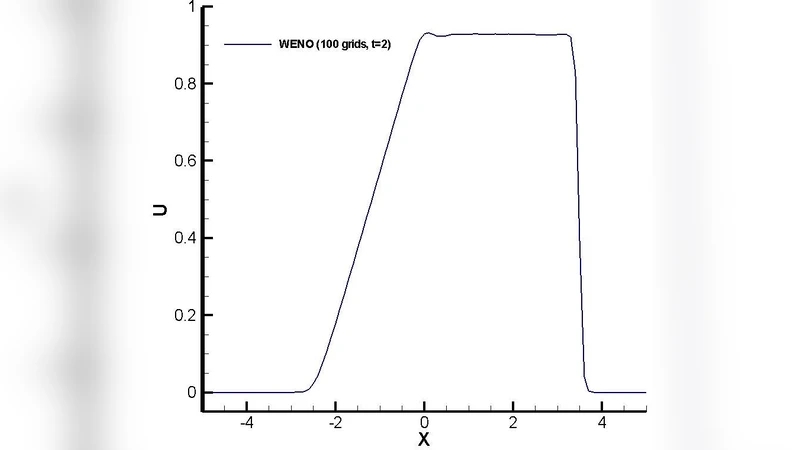
- 1‑D strong and weak shocks – The detector identifies all shocks with 100 % success, and the hybrid scheme reduces L₂‑norm errors by roughly 30 % compared with a conventional TVD‑MUSCL approach.
- 2‑D shock‑boundary‑layer interaction – High‑frequency turbulent structures downstream of the shock are retained, whereas a standard shock‑capturing scheme smears them out.
- Expansion‑wave with superimposed high‑frequency oscillations – The detector correctly classifies the expansion wave as smooth, preserving phase accuracy and avoiding artificial diffusion.
- Multiphase interface with embedded shock – The two‑stage test distinguishes the material interface from the shock, allowing each to be treated with the appropriate stencil and preventing interface thickening.
Across all cases, the method demonstrates (i) high sensitivity to genuine discontinuities, (ii) immunity to misclassifying high‑frequency content, (iii) elimination of user‑tuned parameters, and (iv) seamless integration into existing solvers.
Implications and Applications
By providing a parameter‑free, physics‑based shock detector coupled with a universally applicable high‑order finite‑difference subroutine, the work addresses a critical bottleneck in computational fluid dynamics and related fields. It enables accurate simulation of phenomena where shocks coexist with delicate high‑frequency dynamics, such as supersonic/hypersonic boundary layers, aero‑acoustic coupling, shock‑induced combustion, seismic wave propagation through heterogeneous media, and even image‑processing algorithms that require edge detection without blurring fine textures. The universal nature of the subroutine promises broad adoption, potentially becoming a standard building block for next‑generation high‑fidelity simulation codes.