Throughput and Collision Analysis of Multi-Channel Multi-Stage Spectrum Sensing Algorithms
Multi-stage sensing is a novel concept that refers to a general class of spectrum sensing algorithms that divide the sensing process into a number of sequential stages. The number of sensing stages and the sensing technique per stage can be used to o…
Authors: Wesam Gabran, Przemys{l}aw Pawe{l}czak, Danijela v{C}abric
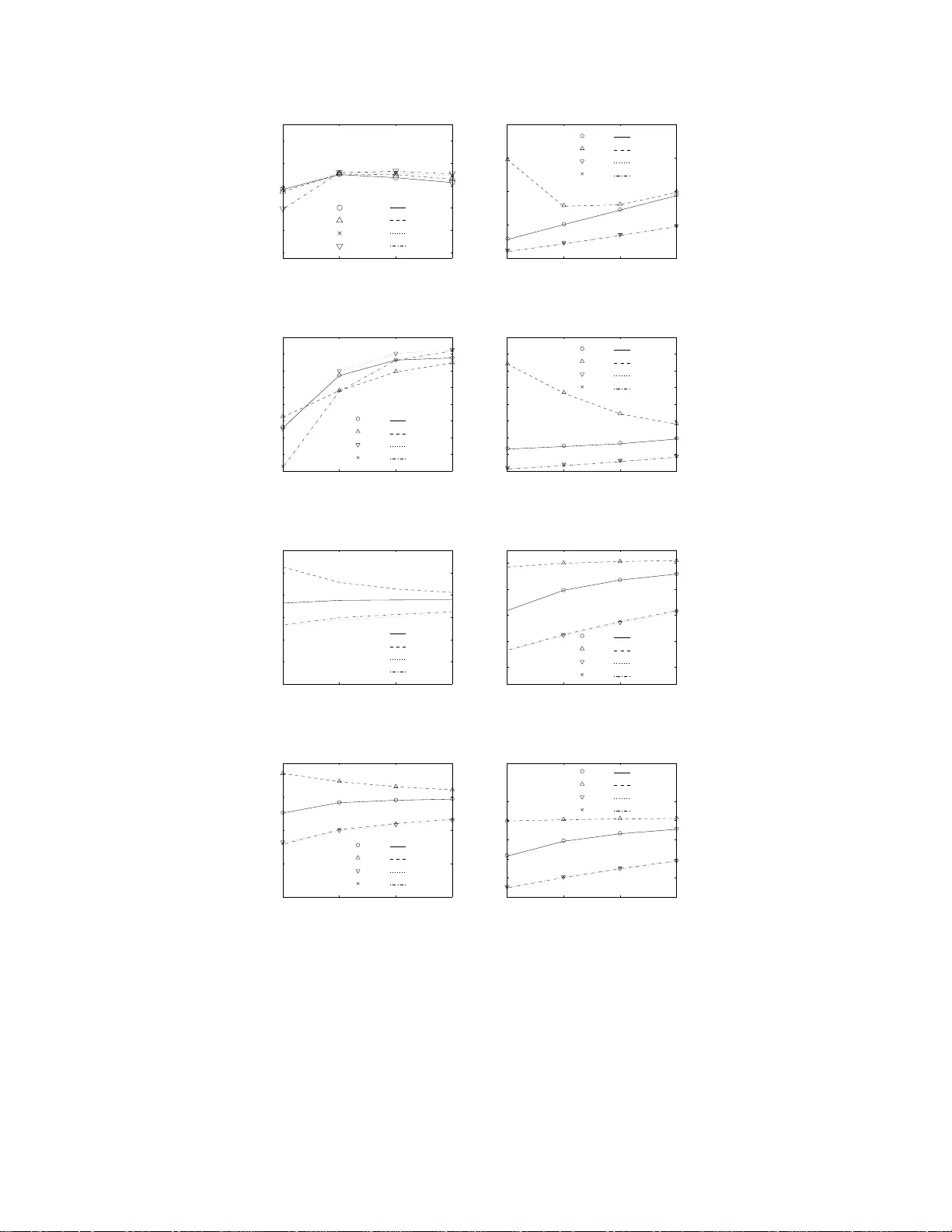
1 Throughp ut and Collision Analysis of Multi-Channel Multi-Stage Spectrum Sensing Algorithms W esam Gabran, Przemysław Pa wełczak, and Danijela ˇ Cabri ´ c Abstract Multi-stage sensing is a novel concept that refers to a gen eral class of spectr um sensing algorith ms that di vide the sensing process into a numb er of sequential stages. T he number of sensing stages and the sensing technique p er stage can be u sed to optimize performa nce with respect to secon dary user throug hput and the collision probability between p rimary and secondary users. So far , the impact of multi-stage sensing on n etwork throughp ut and collision probab ility for a realistic network mo del is relativ ely un explored. Theref ore, we present the first analytical framework wh ich enables per forman ce ev aluation of d ifferent multi-channel multi-stage spectrum sensing algorith ms for Op portun istic Spectrum Access ne tworks. The con tribution of our work lies in stu dying the effect of the following parameters on perfor mance: numb er of sensin g stages, physical layer sensing techn iques and durations per each stage, single and par allel chan nel sensing and access, number of available channels, primary and seco ndary user traffic, buf fering of in coming second ary user traffic, as well as MA C layer sensin g algorithm s. Analyzed perfo rmance metrics include the average second ary user throu ghpu t an d the average co llision probab ility between p rimary and second ary users. Our results show that when th e p robability of primar y user mis-d etection is co nstrained, the perf ormanc e of multi-stage sensing is, in m ost cases, sup erior to the single stage sensing co unterpa rt. Besides, pro longed ch annel observation at the first stage of sensing decreases the collision pro bability considera bly , while keep ing the throughp ut at an ac ceptable lev el. Finally , in realistic prim ary user traffi c scenario s, using two stages o f sensing provides a g ood balance between second ary users through put an d collision prob ability while meeting successfu l detection constraints subjected by Opportu nistic Spectr um Access commu nication. The authors are with the Department of Electri cal Engineering, University of California, Los Angeles, 56-125B Engineering IV Building, Los Angeles, CA 90095-1594, USA (email: { wgabran, przemek, danijela } @ee.ucla.edu). Part of this work has been accepted to the proceedings of IE EE DySP AN, Apr . 3–6, 2011, Aachen, G ermany , EU [ 1]. 2 I . I N T RO D U C T I O N Opportunistic Spe ctrum Acce ss (OSA) radios are wireless communica tion devices tha t exploit tem- porarily vacant license d frequency bands [2], [3]. T o be able to use thes e spec tral vacancies, OSA radios need to sen se the a ctivit y o f the licensed use r in the frequen cy bands of interest. As spectrum se nsing is the e nabling tech nology for OSA, ma ny sensing techniques have be en propo sed in the literature covering a variety of d esign asp ects [4]. This includ es diff erent se nsing me chanisms at the physical layer as well as various co llaborati ve se nsing techn iques a nd mea surement fusion methods at the link layer . In a c on ventional spectrum se nsing algorithm, a OS A radio (denoted later a s Secon dary User (SU) radio) has to periodically scan the licens ed spectrum for any incoming Primary (licensed) U sers (PUs), and detec t the PUs with a p redetermined probability . When the SU radio’ s spectrum sensing phys ical layer triggers a n alarm that a PU e xists, i.e. due to a successful de tection or a false alarm, the SU radio should stop transmission on the respective chan nel. Howe ver , the s ensing proc edure might res ult in a false alarm, thus, reduc ing the cha nnel acc ess opportunity for the SU radio. The probability of a false alarm c an be decreas ed by , e.g. incre asing the s ensing time, howev er , this might lead to a decrease in the throughput achieved by the SU device, as demonstrated in e.g. [5]–[7]. Beside s, the prob ability of false alarm can be decre ased by altering the dec ision threshold regarding the p resence of the primary user . Ho wever , this leads t o an increase in the probability of a collision be tween the SU rad ios a nd PU devices. This in turn may lead to a dec ease in throughput ca used by packet losses at the SU radio. One o f the ways to increas e chan nel utilization in OSA commu nication is to u se multi-stage sens ing. In multi-stage sensing, an a larm (due to su ccess ful d etection or false alarm) on the PU pres ence is followed by S − 1 cycles of sensing (and potential trans mission). Thu s, the pres ence of a P U would be declared, and the SU rad io would vacate a channe l, if and only if S consecutive alarms are g enerated. The s ensing technique used a t each of the S s tages can be inde pende nt from one anothe r . A ccordingly , multi-stage sensing provides a dditional degrees of freedom to optimi ze pe rformance metrics, namely , throughput of SU rad io and the collision prob ability betwe en PUs and S Us. A. Related W or k Multi-stage sens ing has been introduc ed formally in the IEEE 802.22 stand ard [8], [9], with S = 2 , while the first analyses of a multi-stage sensing a lgorithm have bee n pe rformed in [10], [11] (with S = 2 in case of [11]) only for a single PU channel. Note that [10], [11] did not consider the random nature of the OSA tr a ffic which h as a notable effect on the p erformance of the OSA network. Autho rs in [16] extended their previous work [10] to the case of two physical layer sensing techniques: (i) energy 3 detection and (ii) feature (cyclostationary) detection. Furthermore, pe rfect detection at the last stag e of sensing and zero delay in c hanne l switching is not ass umed. In their mode l, the frequ ency of se nsing the c hanne l increase s when the s ensing proc edure ind icates that PU is possibly presen t. Finally , in [12] a multi-channel s ensing tech nique with S = 2 an d one sen sing algorithm was con sidered, whe re e ach sensing ph ase occ urred conse cutiv e ly in the s ame time slot 1 . B. Our Con tributi on W e conc lude that the literature lac ks a unifie d a nalytical framework that ev a luates multi-stage spec trum sensing op tions when S ≥ 2 , con sidering wide rang e of a lgorithms and parameter setups , sensing techniques , various traf fic conditions for SU and P U radios, SU buf fer av a ilability and multi-chann el acces s. In this paper we provide a comprehen siv e a nalytical frame work that models the mu lti-stage multi-channel sp ectrum sen sing conc ept. Our work is spec ifically related to the recent work of [16], but sho uld be treated as a n ew a pproach for analyzing multi-stage s pectrum s ensing algo rithms. In contrary to [16 ], we provide a mo re rea listic model for PU ac ti v ity , where we consider the PU traf fic , not only in the channel whe re the SU is o perating, but also in all av ailable channels. Furthermore, we ac count for the scarcity in the bandwidth av ailable for OSA op eration where our model ac counts for a limited p ool of av ailable PU chann els. Moreover , our mode l applies to OSA devices that h av e a sing le radio operating on a narrowband ch annel and O SA devices that a re defined to have a stac k of narrowband radios tha t can utilize or s ense multiple PU channe ls at the same time. In contrast to [16], our model ac counts for different traf fic models for the OSA ne twork, inc luding con stant and variable bit rate streams. Besides , the mod el covers un buf fered and buf fered OSA sys tems. Performanc e is quantified by throughput and a new me tric, tha t is not cons idered in [16], which is the collision probab ility be tween the PU traf fic and SU de v ices. W e use the proposed analytical framew ork to evaluate three new multi-stage se nsing a lgorithms that aim at optimizing the aforementioned metrics. In t he context of these algorithms, we introduce a ne w sens ing mode , denoted 1 Note that the id ea of multi-st age sensing is conceptually similar to the multi-dwell algorithms used in CDMA code ac quisition analyzed in [13, Sec. II] or in UWB phase tracking analyzed in [14, Sec. II], [15, Sec. II]. Howe ver , t here are two main dif ferences between multi-stage sensing and multi -dwell acquisition that require a novel modeling approach for multi- stage spectrum sensing. Firstly , in the multi-dwell algorithm, se nsing is performed at each stage i n parallel, i. e. multiple components sense the same signal at the same t ime. This is contrary to multi-stage spectrum sensing where parallel detection is problematic due to the hardware cost. Secondly , the detected signal for multi -dwell acquisition is stationary in the time domain, which cannot be guaranteed in OSA systems, due to the traffic fluctuation of the P U. 4 as pre-se nsing, which tar gets minimizing the c ollision p robability . Gi ven that [16] already e valuated the eff ect of using diff e rent phys ical sensing metho ds, and ch annel switching delay , we do not i nclude it in our s tudy . Since our introduced mode l ac counts for the rando mness of the PU and SU traf fi c, and the most widely used method of analyzing n etwork traffic is via Markov chain analysis [17, Ch. 11], we follo w the s ame approa ch here, jus t like [ 10], [ 16]. The rest of the paper is organized as follo ws. The system mo del is introduced in Se ction II. Th e analytical model is prese nted in Section III, with the multi-stage sensing algo rithm design examples analyze d in Se ction IV. The nume rical results are presented in Section V. Finally , the paper is conclude d in Se ction VI. I I . S Y S T E M M O D E L A. General Assump tions SUs co mmunicate oppo rtunistically over mu ltiple narrowband chan nels of throughput W kbps, tha t are rando mly occu pied by PUs (all v ariables a re summarized in T able I). W e conside r an OSA network compose d of two us ers wh ere one is always the transmitter a nd the other one is always the rec eiv e r . The reduction of the OSA network to only two n odes allows us to n eglect the impact of co llisions of random acces s control pac kets on the performance of spe ctrum sensing algorithms. Note that the s ame as sumption has been used in a n earlier study of multi-stage sensing [10]. Our mod el ca n be extended to the multiple nodes case , howe ver , for the brevity of the d iscussion , this is not a ddresse d here. Fu rthermore, PUs and SUs, are a ssumed to a rri ve an d depa rt a t discre te times that a re multiples o f T , where T is the s lot length in second s. W e ass ume that the transmitting S U transmits the sens ing res ults to the receiving SU through the ded icated c ontrol chan nel. Hen ce, the SU pa ir is perfectly syn chronized . These two as sumptions, vital in s implifying the an alysis, are commo n in spe ctrum s ensing literature, refer to [18] for a good overvie w of related work in this area. Finally , we as sume that the time taken b y the SUs to switch from communicating mode to sens ing mode, or from one cha nnel to a nother , is negligible. In this work we focus on OSA link through put a nd PU/SU c ollision analys is. W e ass ume tha t the obtained OSA network throughput is proportional to the du ration of time the SUs use the ch annel and the nu mber of chan nels utilized. Acc ordingly , throughput decreas es if the SU is idle or sen ses the ch annel. Besides, in ca ses whe re the SU and the PU use the sa me ch annel s imultaneously , we assume that the SU frame c annot be de coded and is considered lost. Furthermore, no acknowledgments are considered for the data transmitted b y SUs. F inally , the frame error rate is a ssumed to be zero on PU free chan nels. 5 T ABLE I S U M M A RY O F V A R I A B L E S U S E D I N T H E P A P E R V ariable Description Unit S , M , N number of: sensing stages, sensing radios, av ailable channels — B , b buf fer size, buf fer utilization — R , G av erage: SU throughput, collision probability bps, — W channel throughput kbps j , J SU state vector: single narrowb and radio case, parallel narrowb and radio case — Γ , Γ S ( Γ A ) set of SU states: feasible, where the SU is sensing (activ e) — Θ , Ψ set of states: single narrowband radio, parallel narrowban d radio — Θ 1 ( Θ 2 ) set of states for single narro wband radio: SU sensing, P U exists (P U absent) on channel — θ v , ψ w state: single narrowban d r adio, parallel narrowban d radio — T , T s , T t slot length, sensing duration at stage S , sensing duration for quiet and pre-sensing (m)s, ( µ ) s, ( µ ) s p , s v ariables denoting: P U, S U — i , x , k , l supporting variab les — c , m indices: channel, radio — n a , n a number of channels wi th PU: arriv als, no arriv als — n d , n d number of channels wi th PU: departures, no departures — p f ,s ( p m,s ) probability of false alarm (mis-detection) at sensing stage — p f ,t ( p m,t ) probability of false alarm (mis-detection) at pre-sensing and quiet modes — p x,a ( p x,d ) probability of arriv al (departure) for user x — w i , v i vector of variables at slot i : single narrowb and radio, parallel narrowband radio — C x supporting vector of v ariables — X , Y v ariables for conditional probabilities: single narro wband radio, parallel narrowband radio — f SU traffic st ate for single channel SUs — F vector of S U traffic state f or parallel narro w band r adio — I , Υ vector of P U states, set of all permutations of I — π , Λ vector of stat ionary probabilities, transition probability matrix — F N i number of frames generated at slot i − 1 f or parallel narrowban d radio — F T i , F B i total number of frames at slot i : av ail able for transmission, buf fered — M F i , M A i total number of radios at slot i : av ailable for transmission, activ e — Ω A i , Ω I i , Ω Q i set of radios at slot i : activ e, idle, quiet — 6 B. SU a nd PU T raf fic Mod el W e assume that the SU sends packet traf fic randomly (either with a constan t or a v a riable bit rate), where pa ckets are di vided into frames. In the idle mode, the SU h as no frames to transfer , w hile in the activ e mode , the SU is either transmitting frames or sensing the cha nnels. The probabilities of arri val and depa rture of a SU f rame are denoted by p s,a and p s,d , res pectively 2 . F urther , we co nsider SU nodes with and without d ata buf fering c apabilities. In the case of unbuf fered SU nodes, incoming frames are discarded when no channe ls a re av ailable for transmission. In a buf fered node case, a buf fer of size B frames is present that stores frames only when the nod e is in a mode of operation where sen sing occ upies the whole ti me s lot. New frames are discarded if the buff er is full . The pres ence of t he buf fer increases the average throu ghput as incoming frames a re not discarded when SUs are sen sing the ch annel for the whole slot length. PU cha nnel occupa ncy is also time varying. T hat is, the probabilities of the start and e nd of a ch annel occupa ncy are de noted b y p p,a and p p,d , res pectively . Finally , the av erage PU occ upancy duration and idle times are assu med to be the same for e very PU channel. C. Multi-Sta ge Sensing Algorithms When a SU transmitter g enerates a n ew packet, it first sen ds a reque st to s end the pa cket on the dedicated c ontrol c hannel to the S U rec eiv er . Both the sender a nd the receiv er are c onstantly tuned to the c ontrol channel du ring the idle mode. The connection e stablishment t ime is assu med to be sma ll i n comparison to the sub seque nt transmission time and can therefore be neglected. Once co nnection is establishe d, the s ending SU node s tarts with the first stage of the multi-stage sensing algorithm on the first PU ch annel from a list of av ailable PU chan nels. In ev e ry s tage, the SU transmitter first s enses the channe l for T s < T se conds (except in the sp ecial cases , explained later in this section, w here se nsing occ upies the whole time slot). Immediately after s ensing, in the same slot, a SU frame of duration T − T s second s is sent regardles s of the sensing procedure outcome 3 . If the ou tcome 2 Note that the arri val and departure rates of the SU frames are c onstant and are independen t of the P U state an d t he SU sensing mechanism performance through out the model. This assump tion is typical for system le vel analysis of OSA netw orks. Inclusion of S U tr af fic which is dependen t on the PU state in the model will make the observ ation of the S U network performance dif fi cult, e.g. it wil l be hard to infer whether the decrease in throughput is a result of decreasing SU traffic or the effect of multi- stage sensing algorithm. While the inclusion of the PU-depende nt SU traffic in our model is an interesting topic to con sider , we leav e it for future studies. 3 Note that contrary to [10], [ 16] we do not assume a varying sensing time at each stage. V arying sensing t ime would complicate the pack et forwarding process as frames always hav e a fi xed l ength and cannot adapt to v arying sensing duration. 7 of the se nsing procedure at stage j indicates that a PU is possibly p resent, the S U node s proce ed to the next se nsing s tage. If the outcome o f the se nsing p rocedure at stage j indica tes that the PU is pos sibly absent, the SUs start a new multi-stage sensing cycle. The probabilities of false alarm and mis-detec tion for any o f the S stages of multi-stage sens ing are denoted by p f ,s and p m,s , respe cti vely . Note that, g enerally , increasing T s decreas es p f ,s and p m,s . On the other h and, this lea ds to a de crease in the SUs throughp ut, as more ti me is spe nt o n sen sing for PU activit y . Also no te that SUs can transmit during each stage of the s ensing cycle even thou gh the PU is present a s a result of a mis-detection, which is also the ca se for single-stage sens ing algorithms. The multi-stage sp ectrum s ensing algorithm might outpe rform the single-stage sensing counterpa rt as a result o f increa sed false a larm proba bility . In s ingle-stage se nsing algorithms, a single false alarm force s the S U to s top transmission immediately , while in the cas e of multi-stage spectrum sens ing, the SU checks in S c onsec uti ve sen sing stages if a PU is actua lly on the c hanne l withou t stop ping the on-going communication. This might improve the SUs’ utilization of chann el v aca ncies sp ecially in scenarios where the false alarm probability is high and/or t he PU traffic is slo w . This is further explored in Section V. In the multi-stage sp ectrum s ensing algorithm, the SU transmission continues o n the res pectiv e chan nel until the SU detects the PU prese nce in a ll S stages of sen sing till the las t stage. The SUs may then switch to the next chan nel and restart the multi-stage spec trum sensing algorithm, or stay on the sa me channe l in a prolonged sensing stage that in volves no transmission, dep ending on the radio architecture as explaine d in the foll owing sections . 1) Multi-channel Sensing using a Single Narr o wband Radio: First, we focus on OSA node s with o nly one radio for sen sing or commu nication which can operate only on one frequency ban d a t a time. SUs can s witch to a d if feren t na rro w freque ncy band whe n they de cide to vacate their cu rrent band due to the p ossible prese nce of a PU. The propos ed model serves as a gen eral framew ork en abling the analysis of any multi -stage sens ing algorithm. Due to the infinite numbe r of po ssibilities of multi-stage sensing a lgorithms, we focus our analysis on the algorithm prese nted in the IEEE 802.22 s tandard [8], as well as o ur proposed extensions. The ba sic a lgorithm operates a s follo ws . Whe n the SUs reach the last sta ge o f multi-stage s ensing a nd the outcome of the s ensing p rocedure indicates that a PU is pos sibly present, the SUs switch to a prolonge d channe l observation stage. W e den ote this s tage by the quiet mode . In the qu iet mode, the SUs stay on that channe l for the who le slot duration T t = T , to sens e for PUs. If the outcome of the se nsing proc edure at the quiet mode indicates that a PU is p ossibly present, the SUs switch to ano ther PU cha nnel an d begin a new mu lti-stage s ensing cycle. Othe rwise, the SUs s tay on the same channe l and restart the multi-stage 8 sensing cycle to detect inc oming PUs o r a PU that was mis-detected . Regarding the quiet mode, a f a lse alarm with probability p f ,t , o r a mis-detec tion with p robability p m,t can happ en (just as in [16], but contrary to [10], where detection at this mod e of operation is as sumed perfect). Since T t > T s , the n p f ,t and p m,t can be cho sen to be less than p f ,s and p m,s , respectively . This means that the sensing p rocedure for the prolong ed chann el ob servation stage, also called fine se nsing in the IEEE 802.2 2 sta ndard [8], has higher prec ision than that for stag es 1 to S . Ho wever , this c omes at the expe nse of a potential dec rease in chan nel utilization by the SU. The motiv ation behind the quiet mode is to d ecrease the probability o f the SU leaving a vacant ch annel b ased on false alarms (the impact of the qu iet mod e on the multi-stage spectrum s ensing pe rformance is d iscuss ed in more detail in Section V). In a ddition to the aforementione d algorithm, we propo se and a nalyze algorithms which in volve the usage of a prolonged cha nnel observati on period at the beginning of the sensing cycle. W e denote this prolonged sens ing pe riod by the pre-sensing mode . T he length of this p eriod is T t = T , exactly as in the quiet mode. The motiv ation behind the p re-sensing mode is to decrea se the co llision p robability with the PU, s ince p m,t is sma ll, when the SUs switch to a new c hanne l. At the end of pre-sens ing mode, the SUs enter the first stage of sensing (if no P U ha s be en de tected or a PU has been mis-detected) or switches to a new chann el and s tarts a new sensing proc edure with pre-sensing (if a PU has been d etected or a f alse alarm occurred). The quiet and pre-sen sing stages ha ve a c onsiderab le effect on throu ghput and collisions as our results demonstrate. Acc ordingly , we introduce and analyze algorithms c ombining a ll permutations of these mode s of o peration. 2) Multi-channel Sensing using P arallel Na rr owb and Ra dios: A part from the single narrowband radio case, we c onsider a s ystem, where both SUs have M narrowband radios that can ope rate in pa rallel independ ently . Tha t is, at any given time, ea ch n arrowband rad io c an b e idle, sen sing or co mmunicating regardless of the state of the other radios. Bes ides, the radios may o perate on non-co ntiguous freque ncy bands. In this mode l we assume that the number of a vailable radios is equa l to t he number of available channe ls, N , which is the only relev a nt case in practice . T he incoming frames are divided ac ross the radios with no pri oritization. Each radio follo ws the bas ic s ingle channel multi- stage sen sing algorithm described in the ea rlier s ection, except once the qu iet mod e is reac hed, the radios stay in the q uiet s tage until the outcome o f the sen sing proce dure indicates that the cha nnel is vacant. If, in the quiet mode, the channe l is correctly detected to b e v a cant o r a PU occu pying the channe l is mis-detected, the s ensing procedure outcome would indicate that the chann el is vacant an d the correspond ing ra dio proceeds to the first stag e of the spectrum s ensing algo rithm. 9 I I I . A N A LY T I C A L M O D E L W e prese nt the fou ndation for the analytica l mode l for the s ingle and parallel narrowband radio ca ses separately . W e divide the d iscussion into the Markov chain state definitions, state transition p robabilities, stationary proba bility calcu lation and metrics calculation. A. Multi-channel Sensing us ing a Single Narrowband Radio 1) State and State T ransition Definitions: Let θ v denote the state of the Markov chain, where v = { I , f , j, b, c } . In vector v , c ∈ { 1 , · · · , N } is the ope rating channe l index, whic h denotes the channe l the SU is operating on, or was ope rating on before proc eeding to the idle mode . SU traf fi c status is represented by f , where f = 1 when the SU has a new frame to s end, and f = 0 otherwise. Th e SU mode of operation is represented by j ∈ Γ , where Γ is defined dif fe rently for each single narro wband radio sensing algorithm. For the propose d algorithms, j = 0 implies that the SU is idle and j ∈ { 1 , · · · , S } indicates that the SU is in sensing stage j of multi-stage sen sing, while j = S + 1 and j = S + 2 are the examples o f the special cas es tha t in the context of this work indicate that the SU is in the quiet mode and the pre-sensing mod e, respec ti vely . Define Γ S as a s ubset of Γ representing the mo des of operation where the SU is performing multi- stage sensing . Define Γ A as a subs et of Γ representing the modes of o peration whe re the SU is activ e , that is, the SU is either performing multi-stage sens ing or is in the pre-s ensing or quiet mo de. Γ S = { 1 , · · · , S } for all algorithms, however , Γ A depend s on the specific algorithm. The buf fer le vel at the SU is indic ated by b ∈ { 0 , · · · , B } . Finally , the PU status are described by I , | I | = N , where I ( x ) = 1 when a PU o perates on chann el x , and I ( x ) = 0 o therwise. When transitioning from time slot i to time slot i + 1 , the state of the Markov c hain at slot i + 1 (the SU mode of operation, buf fer level and opera ting ch annel in specific) depen ds on the outco me of the sensing procedure that tests the existence o f a PU du ring time slot i (not time slot i + 1 ). Hence, for mathematical con venience, I is defined to des cribe the PU status in the previous time slot and not the current time slot. The trans ition probability from state θ v 1 to s tate θ v 2 , where v x = { I x , f x , j x , b x , c x } an d subsc ript x = { 1 , 2 } for c , I , f , j , b , deno tes current and next time slots, resp ectiv ely , is expres sed a s Pr ( X ) = U ( X ) 3 Y k =1 Pr k ( X ) , (1) where again, for notational con venience, X , { θ v 2 | θ v 1 } . In (1), Pr 1 ( · ) denotes the probability of PU status chan ge, Pr 2 ( · ) den otes the probab ility of SU traffic status cha nge, Pr 3 ( · ) den otes the probab ilities of the s ensing proce dures o utcomes, and U ( x ) is the transition feasibility func tion an d equals to one if 10 x belong s to a spe cified set of feas ible state transitions and U ( x ) = 0 o therwise. Since the traffic of the PU a nd SU is inde penden t of the sensing algorithm, Pr 1 ( · ) a nd Pr 2 ( · ) are the same for all parallel narrowband radio a lgorithms, d escribed later in Se ction III-B. Howev er , as Pr 3 ( · ) a nd U ( · ) d escribe transitions in the rad ios mod e o f o peration, they are unique to the s ensing a lgorithm a nd are de scribed in Section IV -A. The transition probabilities are consequ ently used in c alculating the stationary proba bilities as de scribed in the following se ction. 2) Stationary Probability Calcu lation: Define Θ as the set of a ll feas ible Markov cha in states. Then , define Λ a s the tr ansition probability matrix where Λ ( k , l ) den otes the trans ition probability from state Θ ( k ) to s tate Θ ( l ) , where k , l ∈ { 1 , · · · , | Θ |} . Θ is evaluated by creating a vector of un ique states, θ v , for all fea sible combinations of c, j, b, I , f and d irectly mapping them to the values of Θ . Fu rther , defin e π a s the vector of stationa ry p robabilities where π ( k ) is the s tationary probability of state Θ ( k ) . Then π c an be e valuated by solving π = π Λ , knowing that P | Θ | i =1 π ( i ) = 1 . The stationary probab ilities are then us ed to calculate the desired metrics. 3) P e rformanc e Metrics Ca lculation: Based on the s tationary probability vector , π , we compute the av erage throughput o btained by the s econd ary networ k, R , a nd the expected number of collisions b etween the transmitting SU a nd PUs per time slot, G . Defi ne Θ 1 as the s et of states θ v , with j ∈ Γ S and I ( c ) = 1 , i.e. Θ 1 is the set o f states where the SU is pe rforming multi-stage sens ing an d a PU was presen t on the channe l on which the SU was operating d uring the previous time slot. Define Θ 2 as the set of states θ v , with j ∈ Γ S and I ( c ) = 0 . In c alculating R , we assume that the SU frame cannot be decoded in case of a collision betwee n the S U a nd a PU, a nd ac cordingly , R can be expres sed as R = W T − T s T X Θ( i ) ∈ Θ 1 π ( i ) p p,d + X Θ( i ) ∈ Θ 2 π ( i ) (1 − p p,a ) , (2) where ( T − T s ) /T is the portion of a time s lot SU spe nt in transmission. Besides, G c an be expresse d as G = X Θ( i ) ∈ Θ 1 π ( i ) (1 − p p,d ) + X Θ( i ) ∈ Θ 2 π ( i ) p p,a . (3) Note that in (2) a nd (3), the information regarding the PU status acco rding to θ v , given by I , p ertains to that of the pre vious time slot. Accordingly , the probability that no PUs e xist at the current time slot a t channe l c given that I ( c ) = 1 equals p p,d , i.e . the p robability tha t the PU user that was utilizing chan nel c in the pre v ious time slot is not a cti ve during the current time slot. Likewise, the prob ability that a PU is a cti ve on channel c gi ven that I ( c ) = 1 is (1 − p p,d ) . This accoun ts for the p p,d and (1 − p p,a ) terms 11 in (2) and the p p,a and (1 − p p,d ) terms in (3). In the follo wing sec tions we wil l de scribe probabilities governing (1) for e ach sensing algorithm. 4) Definitions of Pr 1 ( · ) a nd Pr 2 ( · ) : Le t n a denote the n umber o f channe ls with PU arri vals, n a denote the numbe r of cha nnels with no PU a rri vals, n d denote the number of chann els with PU d epartures and n d denote the nu mber of cha nnels that remained occup ied by the PU. It follows that n a = I 1 ◦ I 2 , n a = I 1 ◦ I 2 , n d = I 1 ◦ I 2 , and n d = I 1 ◦ I 2 , where x is the bitwise bina ry complement o f x and ◦ is the b ase-10 do t product o perator . According ly , Pr 1 ( · ) is expressed as Pr 1 ( X ) = p n a p,a (1 − p p,a ) n a p n d p,d (1 − p p,d ) n d , (4) where I 1 , I 2 ∈ Υ and Υ is the set of all 2 N permutations of I . Pr 2 ( · ) is expressed as Pr 2 ( X ) = 1 − p s,a , f 1 = f 2 = 0 , p s,a , f 1 = 0 , f 2 = 1 , p s,d , f 1 = 1 , f 2 = 0 , 1 − p s,d , f 1 = f 2 = 1 . (5) B. Multi-channel Sensing us ing P arallel Nar r owban d Rad ios 1) State an d State T ransition Definitions: Le t ψ w denote the states of the Ma rkov chain, whe re w = { I , F , J, b } . In w , I and b are d efined the s ame a s for the single narrowband radio c ase. Le t ψ w i denote the Marko v cha in state at time slot i , where w i = { I i , F i , J i , b i } . In the context of our work, the parallel channe l SU is assumed to have M single channel rad ios, the rad io states are d escribed by J , | J | = M , where J ( x ) ∈ Γ describes the mode of operation of radio x . For the cons idered a lgorithm Γ = { 0 , · · · , S + 1 } and J ( x ) = S + 1 indicates tha t radio x is in the qu iet mode. The rest of the radio modes of operation are de fined as for the s ingle narrowband radio cas e. Furthermore, Γ S = { 1 , · · · , S } , as in the case of s inge parallel radios , defines the subse t of Γ that rep resents the mod es of op eration where the SU radio is performing mult i-stage sensing. SU traf fic is as sumed to be in the form of a frame stream with frame arri val and depa rture probab ilities as in the sing le narrowband radio cas e. T he diff erence is that up to M frames c an be gen erated per time slot. Thus , for analysis, a slot can be hypothetically segmented to M parts where a new fr ame ca n be generated at each part. T he state o f thes e frames is represented by F i , | F i | = M , where F i ( x ) = 1 if a frame was created at di vision x of slot i − 1 a nd F i ( x ) = 0 otherwise. Hence, the total numbe r of frames generated at slot i − 1 , denoted by F N i , c an be express ed as F N i = P M x =1 F i ( x ) . These frames 12 are ac cumulated with buf fered frames from time slot i − 1 and are rea dy for transmission at time slot i . Th e excess frames tha t c annot be transmitted at time slot i due to the limited n umber of av ailable channe ls are buf fered wh ere a ma ximum o f B frames can be stored. The total number of frames av a ilable for transmission at time s lot i , denoted by F T i , can be express ed as F T i = b i − 1 + F N i where b i − 1 is the number of buf fered frames f rom time s lot i − 1 . Radios tha t are in the quiet mo de at slot i are not us ed for frame transmission. Hence, the total number of radios avail able for frame trans mission at slot i can be expressed as M F i = P M m =1 V ( J i ( m )) where V ( J i ( m )) = 1 when J i ( m ) 6 = S + 1 and V ( J i ( m )) = 0 , otherwise. Accordingly , the total number of radios that will be activ e at slot i , which equals the total number of frames that will be trans mitted, is M A i = m in { F T i , M F i } . The se radios a re selected from the set of radios that are av a ilable for frame trans mission a t slot i in as cending order of the radio indices (due to the symme try of the system). Denote the set of rad ios t hat will be acti ve at slot i by Ω A i where | Ω A i | = M A i . If M F i > M A i , the extra radios that are available for frame transmiss ion at slot i will be idle. Den ote the se t of these radios by Ω I i where | Ω I i | = m ax { 0 , M F i − F T i } . Radios that are in the quiet mode will stay in the quiet mode until t he outcome of the se nsing proce dure indica tes the absence o f a PU. Den ote the set of radios that are in the q uiet mode at slot i by Ω Q i where | Ω Q i | = M − M F i . If M F i ≥ F T i , then M A i = F T i and all a vailable frames will be transmitted, thus, b i = 0 . Otherwise, M A i < F T i and o nly M A i frames wi ll be transmitted, he nce, b i = min { B , F T i − M A i } . The rest of the frames, if any , will be dropped. Th e transition prob ability from state ψ w 1 to sta te ψ w 2 is given by Pr ( Y ) = U ( Y ) 3 Y k =1 Pr k ( Y ) , (6) where, for no tational conv enience, Y , { ψ w 2 | ψ w 1 } . In (6), Pr 1 ( · ) rep resents the proba bility of PU status change , Pr 2 ( · ) den otes the probability of SU traf fic status change , Pr 3 ( · ) represe nts the probabilities of the sen sing proc edures outc omes, and U ( · ) is the transition feasibility func tion a nd U ( x ) = 1 if x belongs to a spec ified set of feasible state transitions and U ( x ) = 0 otherwise. Sinc e the traf fic of the PU and SU is independe nt of the sensing algorithm, P r 1 ( · ) a nd Pr 2 ( · ) a re the s ame for all algo rithms. Howe ver , a s Pr 3 ( · ) and U ( · ) d escribe transitions in the radios mo de of o peration, they are uniqu e to the sensing a lgorithm and are described in Section IV -B. 2) Stationary Pr obab ility Calculation: D enote Ψ a s the s et o f all feasible states. Ψ is evaluated by creating a vector of unique states , ψ w for all feasible combinations of J, b, I , F and directly mapping them to the values of Ψ . De fine π as the vector o f stationary probabilities wh ere π ( k ) is the stationary probability of state Ψ ( k ) , wh ere k ∈ { 1 , · · · , | Ψ |} . The n π can be ev alua ted by solving π = π Ψ , knowing 13 that P | Ψ | i =1 π ( i ) = 1 . 3) P e rformanc e Metrics Ca lculation: Th e throughp ut, R , can be e xpresse d as R = W T − T s T | Ψ | X k =1 M X m =1 π ( k ) [ p p,d U a ( J k ( m ) , I k ( m )) + (1 − p p,a ) U b ( J k ( m ) , I k ( m ))] , (7) where U a ( j, i ) = 1 if j ∈ Γ S and i = 1 , a nd z ero otherwise ; U b ( j, i ) = 1 if j ∈ Γ S and i = 0 , a nd z ero otherwise. J k ( m ) and I k ( m ) are J and I for radio m at state k , respectiv e ly . The expe cted nu mber of collisions, G , can b e e xpresse d as G = | Ψ | X k =1 M X m =1 π ( k ) [(1 − p p,d ) U a ( J k ( m ) , I k ( m )) + p p,a U b ( J k ( m ) , I k ( m ))] . (8) 4) Definitions o f Pr 1 ( · ) and Pr 2 ( · ) : Pr 1 ( · ) is defined as in (4). The express ion for Pr 2 ( · ) is an extension to t hat of the single chan nel case. He nce, Pr 2 ( Y ) = Pr S ( F 2 (1) | F 1 ( M )) M − 1 Y m =1 Pr S ( F 2 ( m + 1) | F 2 ( m )) , (9) where Pr S ( · ) is defined as (5) replacing f 1 with x and f 2 with y . I V . M U L T I - S T AG E S P E C T RU M S E N S I N G A L G O R I T H M E X A M P L E S : A N A L Y S I S W e prese nt different examples of multi-stages s ensing algo rithms. As mentioned in Se ction III-A1, Pr 3 ( · ) a nd U ( · ) are un ique to the sensing a lgorithms an d are thus d eri ved h ere. A. Multi-channel Sensing us ing a Single Narrowband Radio Before proceeding with the desc ription of Pr 3 ( · ) a nd U ( · ) , we denote transitions wh ere the SU stays on the same channel as C 1 , { c 1 = c 2 } . Further , deno te transitions where the SU switches to the next channe l a s C 2 , { c 1 < M , c 2 = c 1 + 1 or c 1 = M , c 2 = 1 } . a) No Pr e -sensing, Quiet mod e (P 0 Q 1 ): This is the algorithm presented in the IEEE 802.22 stan- dard [8]. Since it features a quiet mode but no p re-sensing mode, thus Γ = { 0 , · · · , S + 1 } a nd Γ A = { 1 , · · · , S + 1 } (note that Γ S = { 1 , . . . , S } is defi ned in the same way as in Se ction III-A1). 14 Then Pr 3 ( Y ) = 1 , j 1 = 0 or j 2 = 0 , C 1 , (10a) p f ,s , I 2 ( c 1 ) = 0 , j 1 ∈ Γ S , j 2 = j 1 + 1 , C 1 , (10b) p f ,t , I 2 ( c 1 ) = 0 , j 1 = S + 1 , j 2 = 1 , C 2 , (10c) 1 − p f ,s , I 2 ( c 1 ) = 0 , j 1 ∈ Γ S , j 2 = 1 , C 1 , (10d) 1 − p f ,t , I 2 ( c 1 ) = 0 , j 1 = S + 1 , j 2 = 1 , C 1 , (10e) 1 − p m,s , I 2 ( c 1 ) = 1 , j 1 ∈ Γ S , j 2 = j 1 + 1 , C 1 , (10f) 1 − p m,t , I 2 ( c 1 ) = 1 , j 1 = S + 1 , j 2 = 1 , C 2 , (10g) p m,s , I 2 ( c 1 ) = 1 , j 1 ∈ Γ S , j 2 = 1 , C 1 , (10h) p m,t , I 2 ( c 1 ) = 1 , j 1 = S + 1 , j 2 = 1 , C 1 , (10i) 0 , otherwise. (10j) W e briefly explain the conditions (10a)–(10i). Transitions to and from the idle mode do not in volve sensing, hence, Pr 3 ( · ) = 1 for transitions where j 1 = 0 or j 2 = 0 as shown in (10a). The cases where the SU is at any sensing s tage and proceeds to the next s tage, based o n a false alarm or a succes sful detection of a P U, are represented by (10b) and (10f ), respectively . The cases where the SU is in the quiet mode and switches to another channel, based on a f a lse alarm or a success ful detec tion of a PU, are represented b y (10c) and (10 g), re spectively . The case s where the S U p roceeds from an activ e mode of ope ration to the first stag e of sen sing, ba sed on c orrectly detecting the ab sence of PUs, are represen ted by (10d) and (10e). The cases wh ere the SU proceed s from an activ e s tage to the first stage of s ensing, based on a mis-detec tion of a PU, are represented by (10h) a nd (10i), respecti vely . Denote trans itions where the buff e r level remains un chang ed and a new frame is produc ed at the next state as C 3 , { b 1 = b 2 , f 2 = 1 } . Denote transitions where the buf fer level dec reases by one frame and no new frames a re produced at the next state as C 4 , { b 2 = b 1 − 1 , b 1 > 0 , f 2 = 0 } . T hen, feas ible ca ses 15 where the SU stays on the s ame chan nel, C 1 , are U ( · ) = 1 ⇐ ⇒ j 1 ∈ { 0 , · · · , S } , j 2 = 0 , b 2 = f 2 = 0 , (11a) j 1 = S + 1 , j 2 = f 2 = B = 0 , (11b) j 1 = 0 , j 2 = 1 , b 2 = 0 , f 2 = 1 , (11c) j 1 ∈ { 1 , · · · , S − 1 } , j 2 = j 1 + 1 , C 3 or C 4 , (11d) j 1 = S , j 2 = S + 1 , f 2 = 1 , b 2 = m in( b 1 + 1 , B ) , (11e) j 1 = S , j 2 = S + 1 , f 2 = 0 , b 2 = b 1 , b 1 > 0 , (11f) j 1 ∈ Γ A , j 2 = 1 , C 3 or C 4 , (11g) The fea sible cas e where the SU switches to the n ext channe l, C 2 , is U ( · ) = 1 ⇐ ⇒ j 1 = S + 1 , j 2 = 1 , C 3 or C 4 . (12) W e explain the con ditions behind U ( · ) . A S U that is in the idle mode or is performing multi-stage sens ing stays at or proceeds to the idle mode , resp ectiv ely , i f no new frames a re ge nerated and the buff e r is empty , as represen ted in (11 a). A SU with a buf fe r that is operating in the quiet mode must have a t least one frame in its buf fer , as otherwise, the SU s hould be in the idle mode. Howe ver , if the SU has n o buff er , it proceeds to the idle mode if the re are no new gen erated frames, as shown in (11b). An idle SU p roceeds to the first stag e of s ensing whe never a new frame is generated, the SU transmits the frame and the buf fer remains empty a s rep resented in (11 c). Condition (11 d) accoun ts for the ca se when a SU is in one of the first S − 1 sensing stage s with a new gen erated frame and/or h as a t leas t one f rame i n its b uff e r . Then the SU may proc eed to the next sensing stage (bas ed on the outcome of the sensing procedure). Furthermore, if this SU has a new gene rated frame, the buf fer level remains unc hanged ; otherwise, the buf fer lev e l decreases by one. If the SU switches to the quiet mode and has a ne w generated frame as shown in (11 e), the buf fer le vel inc reases b y one if the b u f fer is not full, othe rwise, the new frame is discarded. If the SU is a t the last stag e of sensing with at lea st one frame in its buf fer and no n ew frames are generated, the S U ma y s witch to the q uiet mod e (base d on the sens ing procedu re outcome ) and the buf fer level stays the same as presented in (11f). An acti ve SU wit h frames to trans mit tha t mis-detec ts a PU or correctly detec ts the absenc e of a PU proce eds to the first s tage o f se nsing. In this case , as described in (11g), if the SU ha s a new generated frame, the buf fer level remains unc hanged ; otherwise, the buf fer lev e l decreas es by one. If a SU is in the quiet mode and has frames to trans mit and the sensing procedure results in a false alarm or a succes sful detection of a PU, the SU switches to a new cha nnel 16 and s tarts a t the first stage of sen sing. If this SU has a n ew generated frame, the b u f fer le vel re mains unchan ged; othe rwise, the b uffer lev el decrea ses by on e. This transition is s hown in (12). b) No Pre-sensing, No Quiet Mode (P 0 Q 0 ): This algorithm aims at redu cing the time spent in sensing b y omitting the pre-sensing a nd qu iet mod es o f op eration. When the o utcome of the s ensing procedure at stage S indica tes that a PU is possibly prese nt, the SU switches to a new c hannel and restart the sensing procedure. Then , Γ = { 0 , 1 , · · · , S } and Γ A = Γ S = { 1 , · · · , S } . Since there a re no pre-sensing or quiet mod es, frames do not get buf fered . Accordingly , we a ssume the abs ence o f a buf fer , thus, B = b 1 = b 2 = 0 . Hence Pr 3 ( Y ) = 1 , j 1 = 0 or j 2 = 0 , C 1 ; p f ,s , I 2 ( c 1 ) = 0 , j 1 ∈ { 1 , · · · , S − 1 } , j 2 = j 1 + 1 , C 1 or I 2 ( c 1 ) = 0 , j 1 = S , j 2 = 1 , C 2 ; 1 − p f ,s , I 2 ( c 1 ) = 0 , j 1 ∈ Γ S , j 2 = 1 , C 1 ; 1 − p m,s , I 2 ( c 1 ) = 1 , j 1 ∈ { 1 , · · · , S − 1 } , j 2 = j 1 + 1 , C 1 or I 2 ( c 1 ) = 1 , j 1 = S , j 2 = 1 , C 2 ; p m,s , I 2 ( c 1 ) = 1 , j 1 ∈ Γ S , j 2 = 1 , C 1 ; 0 , otherwise. (13) The deriv ation of P r 3 ( · ) for P 0 Q 0 follo ws that for P 0 Q 1 . The difference in expressions is caus ed b y the absenc e of the quiet mode. Regarding U ( · ) , fea sible trans itions where the SU stays o n the s ame channe l, C 1 , a re U ( · ) = 1 ⇐ ⇒ j 1 ∈ Γ , j 2 = 0 , f 2 = 0 , (14a) j 1 ∈ Γ , j 2 = 1 , f 2 = 1 , (14b) j 1 ∈ { 1 , · · · , S − 1 } , j 2 = j 1 + 1 , f 2 = 1 . (14c) The feasible case where the SU switches to the next channe l ( c 1 < M , c 2 = c 1 + 1 or c 1 = M , c 2 = 1 ) is U ( · ) = 1 ⇐ ⇒ j 1 = S , j 2 = 1 , f 2 = 1 . (15) Since a buf fer is unne cess ary for this algorithm, a SU with no new gene rated frames proceeds to the idle mode irrespective of its previous state as shown in (14a). C ondition (14b) indicates that a SU with a new gen erated frame proceeds to the first s tage of sens ing in ca se of mis-detecting or correctly de tecting the absen ce of a PU. In case of a false alarm or correctly detec ting a PU, if the SU is at any of the first S − 1 sensing stages, the SU stays o n the same ch annel a nd proceeds to the next s ensing stage as 17 presented in (14c ). Otherwise, if the SU is a t the las t stage of sensing, it switches to the next channe l starting a t the first s ensing sta ge as shown in (15 ). c) Pr e -sensing, Quiet Mod e (P 1 Q 1 ): As a comp lement to P 0 Q 0 , this algorithm features b oth a pre- sensing a s well a s a quiet mode of ope ration. If the outco me of the s ensing proced ure at the pre-sen sing mode indicates tha t a PU is possibly prese nt, due to a false alarm with probability p f ,t or a s ucess full detection with prob ability 1 − p m,t , the SU s witch to the c onsec uti ve channe l starting with the pre-sensing mode. Otherwise, the SU proc eeds to the first stag e of s ensing at the same ch annel. In this algorithm, Γ = { 0 , · · · , S +2 } a nd Γ A = { 1 , · · · , S + 2 } . The e x pression f o r Pr 3 ( · ) follows that for P 0 Q 1 as described in (10) but, due to the introdu ction o f the p re-sensing mode, the condition o n j 1 in (10c ), (10e), (10g) a nd (10i) c hanges to j 1 ∈ { S + 1 , S + 2 } . Also, the co ndition on j 2 in (10c) an d (10g) chan ges to j 2 = S + 2 . The expression for U ( · ) for c ases where the SUs stay o n the sa me chann el follows that for P 0 Q 1 as giv e n in (11) with the followi ng alterations: (11b) ch anges to j 1 ∈ { S + 1 , S + 2 } , j 2 = f 2 = B = 0 , and (11c) cha nges to j 1 = 0 , j 2 = S + 2 , b 2 = m in( b 1 + 1 , B ) , f 2 = 1 . For transitions where the SU switche s to the next cha nnel U ( · ) = 1 ⇐ ⇒ j 1 ∈ { S + 1 , S + 2 } , j 2 = S + 2 , f 2 = 1 , b 2 = m in( b 1 + 1 , B ) , j 1 ∈ { S + 1 , S + 2 } , j 2 = S + 2 , f 2 = 0 , b 2 = b 1 , b 1 > 0 , (16) d) Pr e -sensing, No Quiet Mode (P 1 Q 0 ): T o in vestigate the eff ect of introduc ing the pre-sensing mode o f op eration only , we propo se and d escribe an a lgorithm that features a pre -sensing mode with no quiet mode. H ence, Γ = { 0 , · · · , S, S + 2 } and Γ A = { 1 , · · · , S, S + 2 } . The expression for Pr 3 ( · ) is as giv e n in (10) but the condition on j 1 in (10b) and (10f) chang es to j 1 ∈ { 1 , · · · , S − 1 } . The c ondition on j 1 in (10e ) an d (10 i) cha nges to j 1 = S + 2 . Fina lly , the co nditions on j 1 and j 2 in (10c) and (10g) change to j 1 ∈ { S, S + 2 } and j 2 = S + 2 . This is to accommod ate for the abse nce of the quiet mode and the presence of the p re-sensing mode . Regarding U ( · ) , conditions for trans itions for wh ich U ( · ) = 1 where the SU s tays on the same c hanne l are given as (11) with the follo wing alterations. Con dition (11b) is chang ed to j 1 = S + 2 , j 2 = f 2 = B = 0 . Con dition (11c) is altered to j 1 = 0 , j 2 = S + 2 , b 2 = m in( b 1 + 1 , B ) , f 2 = 1 . Conditions (11e) a nd (11f) are dropp ed as there is no qu iet mod e. Condition (11c) is altered to accommoda te for the pre-sensing mo de; an idle SU with a n ew generated frame s witches to the pre-sens ing mode a nd buf fers the new frame if a buf fer is av ailable. Feas ible transitions w here the SU s witches to the next channe l a re given as (16 ) r eplacing j 1 ∈ { S + 1 , S + 2 } with j 1 ∈ { S, S + 2 } . It implies that if the SU is at the last sens ing stage or in the pre-sen sing mode the SU may switch to the next chan nel starting in the pre-sensing mode de pending on the sensing proced ure outcome. Sinc e the SU is no t allowed to 18 communicate on the cha nnel while in the pre-se nsing mode, if a new frame is genera ted, the frame is either buf fered, if the buf fer is not full, or dropped if the buf fer is full o r if there is n o buf fer . Otherwise, if n o new frames are generated, the b uffer level remains unchanged. B. Multi-channel Sensing us ing P arallel Nar r owban d Rad ios For the parallel narrowband radios case, we des cribe one algorithm implementation, no ting that deriv a- tions for othe r algorithms (not presented in this pa per) may follo w from Section IV -A. Pr 3 ( · ) , can be expressed as Pr 3 ( Y ) = Y m 1 ∈ Ω A 1 Pr 3 , 1 ( Y ) Y m 2 ∈ Ω Q 1 Pr 3 , 2 ( Y ) Y m 3 ∈ Ω I 1 Pr 3 , 3 ( Y ) , (17 ) where Pr 3 , 1 ( · ) , Pr 3 , 2 ( · ) , and Pr 3 , 3 ( · ) represe nt the transition p robabilities for radios that a re elemen ts of sets Ω A 1 , Ω Q 1 , and Ω I 1 , introduc ed in Section III-B1, res pectiv ely . Pr 3 , 1 ( · ) can be expressed as Pr 3 , 1 ( Y ) = 1 , J 1 ( m ) ∈ { 1 , · · · , S − 1 } , J 2 ( m ) = 0; p f ,s , I 2 ( m ) = 0 , J 1 ( m ) ∈ Γ S , J 2 ( m ) = J 1 ( m ) + 1; 1 − p m,s , I 2 ( m ) = 1 , J 1 ( m ) ∈ Γ S , J 2 ( m ) = J 1 ( m ) + 1; 1 − p f ,s , I 2 ( m ) = 0 , J 1 ( m ) ∈ Γ S , J 2 ( m ) = 1 or I 2 ( m ) = 0 , J 1 ( m ) = S , J 2 ( m ) = 0; p m,s , I 2 ( m ) = 1 , J 1 ( m ) ∈ Γ S , J 2 ( m ) = 1 or I 2 ( m ) = 1 , J 1 ( m ) = S , J 2 ( m ) = 0; 0 , otherwise . (18) The expression s shown in (18) follow tha t for (10) whe re they express whether the active radio proceed s to the next sensing stage or ba ck to the first stage of s ensing based on the se nsing d ecision and the presenc e or ab sence of a PU. The only difference is for ca ses wh ere the radio switches to the idle mode. A radio in any of the first S − 1 se nsing s tages ca n switch to the idle mode in case it is n ot need ed for frame transmission. T he outcome o f the sensing proce dure is neglec ted. For a radio that is in the last stage of sensing an d is not neede d for frame transmission, the radio can sw itch to the idle mode only if the sensing proce dure do es n ot d etect a PU. Otherwise, the radio s witches to the quiet mode. Pr 3 , 2 ( · ) 19 can b e express ed a s Pr 3 , 2 ( Y ) = p f ,t , I 2 ( m ) = 0 , J 2 ( m ) = S + 1; 1 − p m,t , I 2 ( m ) = 1 , J 2 ( m ) = S + 1; 1 − p f ,t , I 2 ( m ) = 0 , J 2 ( m ) = 0 or I 2 ( m ) = 0 , J 2 ( m ) = 1; p m,t , I 2 ( m ) = 1 , J 2 ( m ) = 0 or I 2 ( m ) = 1 , J 2 ( m ) = 1; 0 , otherwise . (19) The expres sions des cribe the state trans itions for rad ios in the quiet mo de. In case o f a f als e alarm or a succe ssful detection of a PU, the radio stays in the quiet mode. Otherwise, the radio proc eeds either to the idle mode, in case it is not needed for frame transmission, or to the first stage of spectrum s ensing. Pr 3 , 3 ( · ) c an be expressed as Pr 3 , 3 ( Y ) = 1 , J 2 ( m ) = 0 or J 2 ( m ) = 1 , 0 , otherwise . (20) This express ion is for r adios that are currently in the idle mod e. These rad ios can either sta y in the idle mode, if they are not n eeded for transmission, or p roceed to the first s tage of spec trum sensing, o therwise. No s pectrum sens ing is d one b y idle radios. Conditions f or feas ible state transitions are given by U ( · ) = 1 ⇐ ⇒ F T 2 ≥ M A 2 , b 2 = m in { F T 2 − M A 2 , B } . (21) These c onditions indicate that the numb er of activ e radios s hould be less than or equ al to the numbe r of frames av a ilable for transmiss ion. Bes ides, since only M A 2 frames c an be transmitted, F T 2 − M A 2 frames will need to be buff ered. Howe ver , as the buf fer can only hold B f rames, the total number of frames that will be b u f fered equa ls min { F T 2 − M A 2 , B } . V . N U M E R I C A L R E S U L T S Due to the vast numbe r of parame ters in the p roposed mo del, we focu s on the results that capture the interplay between PU and SU traf fic and sens ing algo rithms. In specific, we pres ent numerical results showing t hroughput and collision proba bility as a function of the numbe r of sensing stages. Moreover , we i n vestigate the relationship between the sensing tim e and the performance metri cs. Furthermore, w e demonstrate the relationsh ip between buf fer size and the obtaine d throughput. Finally , we comp are the 20 T ABLE II S U M M A RY O F C O M M O N P A R A M E T E R S U S E D I N N U M E R I C A L E V A L UAT I O N Descriptiv e Name Parameter V alues Long- T s Low- p f T s = 0 . 24 T , p f ,s = 0 . 1 Short- T s High- p f T s = 0 . 1 T , p f ,s = 0 . 36 Slow PU traffic p p,a = p p,d = 0 . 01 Fast PU tr affic p p,a = 0 . 5 , p p,d = 0 . 1 performance of single and pa rallel n arrowband radio architec tures. Th e res ults for all proposed algo rithms are shown for single and p arallel na rro wb and radio a rchitectures. W e adopt a set of parameters and assu mptions t h at are common to all sc enarios presented in this section, unless otherwise stated. Spec ifically , we adopt energy d etection a s the physical layer se nsing techn ique. Furthermore, we assu me an A WGN chan nel, where the expressions for the probabilities of false alarm and mis-de tection for such chan nel ca n be foun d in [19, Eq . (12)] and [19, Eq. (14)], resp ectiv ely 4 . T he bandwidth for each PU cha nnel is set to 6 MHz, as in [16, Sec. IV], [10, Sec . IV], the c hanne l throughpu t W = 1 Mbps a nd the SNR at the s ensing receiver is s et to – 10 dB. Slot time is s et to T = 1 ms, as assume d in e.g. [18]. Note tha t we verify all analytical results pres ented in this s ection using Monte Carlo s imulations. A. Single Narr owband Ra dio: Th r oug hput and Collisions versus Numb er of Sta ges W e in vestigate the effect of varyi ng t h e number of sens ing stag es on throughpu t and collision probability for e ach s ensing algorithm in the single n arrowband radio arc hitecture case . W e assume N = 6 channels , which rep resents a typ ical value for multi- c hanne l networks, cf. N ∈ { 2 , . . . , 12 } [18 ]. For the SU traf fic , we ass ume p s,a = 1 an d p s,d = 0 , i.e the SU transmits constan t bit rate traffic, which saturates the channe l. W e consider SUs without buff er , since ou r analysis h as shown that b uffer s ize does no t impact throughput when SU s are always transmitting frames. W e conside r two cases, desc ribed belo w , related to sensing to explore the tradeoff between the sensing time a nd the resulting through put. W e a chieve this by varying the sensing time an d the ene r gy detection sensing threshold while k e eping the proba bility o f mis-detection co nstant at p m,s = 0 . 1 . The selected values for p f ,s are 0.1 and 0.36 which correspond to 4 Note that our model is applicable to any channel model, including the ones discussed in [10], [16] , provided t hat there is an analytical expression li nking the sensing time and the probabilities of false alarm and detection for a giv en S NR. 21 T s = 0 . 24 T a nd T s = 0 . 1 T , respec ti vely . W e den ote the former sens ing technique by long- T s low- p f and the latter by short- T s high- p f . T he energy detection s ensing thresholds for the quiet an d pre-sensing modes of ope ration are the s ame as those for the other stages of se nsing. T wo realistic PU traffic models are conside red: (i) one with slow PU tr affic (r elati ve to the slot duration) with p p,a = p p,d = 0 . 01 , an d (ii) o ne with f a st P U traffic with p p,a = 0 . 5 and p p,d = 0 . 1 [20, T a ble 3]. Results for the slow PU traffic mo del are sho wn in Fig. 1 (a), Fig. 1(b), Fig. 1(c) and Fig. 1(d). From our framew ork, it is appare nt that the up per bound for R equals 1 − p p,a p p,a + p p,d N W . For the slow PU traf fic model, R is upper bounded b y 984.3 kbps. F o r ideal sens ing, that is, if p f ,s = p f ,t = p m,s = p m,t = T s = 0 , R for the four single narro wb and rad ios algorithms approac hes the upper bound. Using only one stage of ideal se nsing results in R tha t is less than 1% below the upper bound. The loss in throughput is cau sed by the time sp ent by the S U in the quiet and pre-se nsing mo des (if they exist for the algorithm) and while transmitting on a ch annel o ccupied by a PU. Howe ver , for sing le s tage non-ideal s ensing, the yielded throughpu t for a ll algorithms is 33–3 9% below the uppe r bound for the long- T s low- p f sensing tec hnique and 38–53% below the upper bo und for the short- T s high- p f sensing technique. W e now in vestigate the los s in R for n on-ideal sens ing for the four algorithms. C onsidering P 0 Q 1 and P 1 Q 0 for S = 1 , it is clear that the quiet mo de leads to a higher R compa red to the pre-sensing mode . This is becau se for P 0 Q 1 , a false alarm causes the SU to proceed from sensing stag e one to the q uiet mode. Howe ver , the quiet mod e features a low p robability of false alarm caus ing the SU to return to stage o ne of sensing, with high probability , and continue communicating on the vacant cha nnel. On the other hand, for P 1 Q 0 , a single f a lse alarm causes the SU to switch to a new c hanne l that might not be vacant. P 0 Q 0 which features no quiet or pre-sensing modes results in a highe r R than P 1 Q 0 for S = 1 . Y et, this come s at the expense of collisions where G for P 0 Q 0 is 1 5 a nd 45 times more than that for P 1 Q 0 for long- T s low- p f and s hort- T s high- p f , respe cti vely . Considering multi-stage sen sing with S > 1 for slow PU traffic, as S increase s, the impa ct o f false alarms on R de creases . This i s becau se more consec uti ve false alarms h ave to be generated i n order t o reach the quiet mod e (for P 0 Q 1 and P 1 Q 1 ) or to switch to the next channel (for P 0 Q 0 and P 1 Q 0 ). O n the other han d, increasing S c auses the SU to take a lon ger time, o n average, to reac h the qu iet mode ba sed on the successful d etection of a PU. This cau ses G to increas e (f o r most algorithms) and c onseq uently leads to a decrease i n R . Thus, S = 2 results in the h ighest R for most algorithms for long- T s low- p f . Howe ver , for short- T s high- p f , R increa ses with inc reasing S due to the dominant effect of false alarms on all algorithms. In c onclusion, for the slow PU traf fi c ca se, multi-stage s ensing provides the flexibility 22 1 2 3 4 140 160 180 200 220 240 Number of Sensing Stages S Throughput R (kbps) (Anal.) P 0 Q 1 (Anal.) P 0 Q 0 (Anal.) P 1 Q 1 (Anal.) P 1 Q 0 (Sim.) P 0 Q 1 (Sim.) P 0 Q 0 (Sim.) P 1 Q 1 (Sim.) P 1 Q 0 (a) 1 2 3 4 0 0.05 0.1 0.15 0.2 Number of Sensing Stages S Collisions per Time Slot G (Anal.) P 0 Q 1 (Anal.) P 0 Q 0 (Anal.) P 1 Q 1 (Anal.) P 1 Q 0 (Sim.) (Sim.) (Sim.) (Sim.) (b) 1 2 3 4 450 500 550 600 650 700 750 800 850 Number of Sensing Stages S Throughput R (kbps) (Anal.) P 0 Q 1 (Anal.) P 0 Q 0 (Anal.) P 1 Q 1 (Anal.) P 1 Q 0 (Sim.) (Sim.) (Sim.) (Sim.) (c) 1 2 3 4 0 0.05 0.1 0.15 0.2 0.25 0.3 0.35 0.4 Number of Sensing Stages S Collisions per Time Slot G (Anal.) P 0 Q 1 (Anal.) P 0 Q 0 (Anal.) P 1 Q 1 (Anal.) P 1 Q 0 (Sim.) (Sim.) (Sim.) (Sim.) (d) 1 2 3 4 0 10 20 30 40 50 60 Number of Sensing Stages S Throughput R (kbps) (Anal.) P 0 Q 1 (Anal.) P 0 Q 0 (Anal.) P 1 Q 1 (Anal.) P 1 Q 0 (e) 1 2 3 4 0 0.2 0.4 0.6 0.8 Number of Sensing Stages S Collisions per Time Slot G (Anal.) P 0 Q 1 (Anal.) P 0 Q 0 (Anal.) P 1 Q 1 (Anal.) P 1 Q 0 (Sim.) (Sim.) (Sim.) (Sim.) (f) 1 2 3 4 0 50 100 150 200 Number of Sensing Stages S Throughput R (kbps) (Anal.) P 0 Q 1 (Anal.) P 0 Q 0 (Anal.) P 1 Q 1 (Anal.) P 1 Q 0 (Sim.) (Sim.) (Sim.) (Sim.) (g) 1 2 3 4 0 0.2 0.4 0.6 0.8 1 Number of Sensing Stages S Collisions per Time Slot G (Anal.) P 0 Q 1 (Anal.) P 0 Q 0 (Anal.) P 1 Q 1 (Anal.) P 1 Q 0 (Sim.) (Sim.) (Sim.) (Sim.) (h) Fig. 1. R and G as functions of S for the single narrowband radio case. (a) and (b) show R and G , respectiv ely , for sl o w PU traffic and long- T s lo w- p f sensing, (c) and (d) show R and G , respectiv ely , for slo w PU traffic and short- T s high- p f sensing, (e) and (f) show R and G , respectiv ely , for fast P U traffic and long- T s lo w- p f sensing, and (g) and (h) sho w R and G , respectiv ely , for fast P U traffic and short- T s high- p f sensing. The slow and fast PU traffic scenarios and the l ong- T s lo w- p f and short- T s high- p f sensing techniques are as explained in Section V -A. Common parameters: N = 6 , T = 1 ms, W = 1 Mbps, p s,a = 1 , p s,d = 0 and B = 0 . 23 to de crease the sensing time while increa sing the resulting throug hput. In our se tup dec reasing T s from T s = 0 . 24 T to T s = 0 . 1 T while increasing S to 4 stages l eads to increasing R by 14%. Regarding the sensing a lgorithm, the pre-se nsing mode results in a c onsiderab le de crease in G . Adding the qu iet mod e to the pre-sens ing mode leads to an inc rease in R for sma ll S , a nd the gain in R is more significan t for higher proba bilities of f a lse alarm. Results for the fast PU traffic case are shown in Fig. 1(e), Fig. 1(f), Fig. 1(g) and Fig. 1(h). As the PU traffic be comes faster , the probability tha t the SU switches to another c hannel increa ses. Hence, the stationary prob ability that the SU ope rates in the pre-sensing or quiet mo des increa ses (for algorithms that have these stage s) cau sing the res ulting R to de crease. For P 0 Q 1 , P 1 Q 1 and P 1 Q 0 , increas ing S decreas es the stationary probability of operating in the p re-sensing and quie t modes and ac cordingly , cause s an increa se in R . P 0 Q 0 exhibits the highe st R for the fast PU traf fic case, ye t, this comes at the expense of collisions where G is up to eigh t times highe r than tha t for algo rithms with pre-sensing. For P 0 Q 0 , increasing the numbe r of se nsing s tages increases the time taken by the SUs to vacate the channe l for an inc oming PU, lead ing to an increa se in G and a dec rease in R . Finally , note that the analytical results match perfectly with the Monte Carlo simulations. B. Single Na rr ow band Radio: Thr oug hput and Collisions v ersus Sens ing T ime P er Stage and Pr o bability of F alse Alarm In this section, we an alyze the effect of varying T s on throughpu t, R , a nd collisions, G , for the different sensing algorithms u sing the single narrowband radio architecture 5 . For this expe riment, in contrary to Section V -A, we s et S = 2 stages, N = 3 cha nnels and B = 2 frames to explore the results from the perspec ti ve of a parame ter set that is different from that o f the p revious s ection. Furthermore, we set p p,a = 0 . 01 , p p,d = 0 . 05 , p s,a = 0 . 1 and we set the ratio W 1 − T s T p s,a p s,a + p s,d (the average generated SU traf fic ) to 500 kbps. For the different values of T s = [50 , 500] µ s , the energy de tection sensing thres hold is chosen to keep p m,s constant at 0 . 1 , while p f ,s = [0 . 23 , 0 . 013] . The unsuccess ful frame deliv ery rate is non-ze ro as frames are lost either beca use of collisions with PU frames or buf fer overflow when the re are no chan nel vacancies. For cla rity of presenta tion, we assume a QoS constraint where t he maximum unsucc essful frame de li very rate is set to 0 . 1 and we d o not present the results tha t do not s atisfy the QoS con straint. 5 More results on the ef fect of T s on the multi-chan nel multi-stage spectrum sensing algorithms in the context of energy consumption are presented in [1 , S ec. IV -B]. 24 50 150 250 350 450 450 460 470 480 490 Sensing Duration T s ( µ s) Throughput R (kbps) (Anal.) P 0 Q 1 (Anal.) P 0 Q 0 (Anal.) P 1 Q 1 (Anal.) P 1 Q 0 0.091 0.034 0.013 0.23 p f,s (Sim.) (Sim.) (Sim.) (Sim.) (a) 50 150 250 350 450 0 0.01 0.02 0.03 0.04 0.05 0.06 Sensing Duration T s ( µ s) Collisions per Time Slot G (Anal.) P 0 Q 1 (Anal.) P 0 Q 0 (Anal.) P 1 Q 1 (Anal.) P 1 Q 0 0.091 0.034 0.013 0.23 p f,s (Sim.) (Sim.) (Sim.) (Sim.) (b) Fig. 2. Single narrowband radios case: (a) throughput R and ( b) colli sion probability G as f unctions of T s . Common parametrs: T = 1 ms, S = 2 , N = 3 , B = 2 , p m,s = 0 . 1 , p p,a = 0 . 01 , p p,d = 0 . 05 , p s,a = 0 . 1 and the generated throughput equals 500 kbps. Note the respectiv e probability of false alarm, p f ,s , for each sensing time are marked at the top of each fi gure. The impact of varying T s on R is sh own in Fig. 2(a). Re sults s how t hat for P 0 Q 1 , P 1 Q 1 and P 1 Q 0 , there is a n optimal value o f T s that ma ximizes throug hput (resulting f rom the s ensing/through put tradeoff [5], [6]) wh ile for P 0 Q 0 , R increases monotonically with T s . T his is b ecaus e increasing T s decreas es the probability of false alarm lead ing to a n increas e in the utilized sp ectral vacancy and hence, an increase in throughput. On the othe r hand, increas ing T s increases the numb er of transmitted frames nee ded to meet the throughput requiremen t. As a result, for long T s , increas ing T s increases the proba bility o f buf fer overflo w ca using a decrease in throu ghput. However , this is not the case for P 0 Q 0 as frames do not ge t buf fered, a s explained in Section IV -A. The relations hip between T s and G is presented in Fig. 2(b). Increa sing T s increases the number of transmitted frames, to maintain g enerated throug hput at 500 kbps, and thus ca uses an increase in the collision probab ility . However , shorter T s results in a higher false ala rm probability . Th is c ause s the SU to switch from a vacant chann el to a new cha nnel tha t might be oc cupied by a PU resulting in a collision. The pre-sens ing stage de crease s collisions ca used by switching to an occu pied channe l. Acco rdingly , for P 1 Q 1 and P 1 Q 0 , G increases monotonically with T s , while on the other han d, the relationsh ip between T s and G is conv ex and non-monotonic for T s for P 1 Q 1 and P 1 Q 0 . Comparing Fig. 2(a) and Fig. 2(b) it is clear that the bes t protocol option (that maximizes throughput, wh ile at the same time minimizes collisions) is P 1 Q 0 . 25 0 1 2 3 4 280 290 300 310 320 330 340 350 Buffer Size B (frames) Throughput R (kbps) (Anal.) P 0 Q 1 (Anal.) P 0 Q 0 (Anal.) P 1 Q 1 (Anal.) P 1 Q 0 (Sim.) P 0 Q 1 (Sim.) P 0 Q 0 (Sim.) P 1 Q 1 (Sim.) P 1 Q 0 (a) 0 1 2 3 4 450 500 550 600 650 Buffer Size B (frames) Throughput R (kbps) (Anal.) P 0 Q 1 (Anal.) P 0 Q 0 (Anal.) P 1 Q 1 (Anal.) P 1 Q 0 (Sim.) P 0 Q 1 (Sim.) P 0 Q 0 (Sim.) P 1 Q 1 (Sim.) P 1 Q 0 (b) Fig. 3. R as a function of B for the single narrowba nd radio case for (a) slow SU traffic and long- T s lo w- p f sensing and (b) fast SU traffic and short- T s high- p f sensing. T he slow and fast SU traffic scenarios are as explained in Section V - C and t he long- T s lo w- p f and short- T s high- p f sensing techniques are as explaine d in Section V -A . Moreover: S = 2 , N = 3 , T = 1 ms, W = 1 Mbps, p p,a = p p,d = 0 . 01 . C. Single Narr owband Ra dio: Th r ough put ve rsus Bu f fer S ize For this experiment, we set S = 2 stages, N = 3 channels, p m,s = 0 . 1 an d p p,a = p p,d = 0 . 01 . W e analyze the two scen arios conside red earlier in Section V -A: (i) on e with s low SU traffic (relativ e to the slot duration) with p s,a = p s,d = 0 . 01 and the long- T s low- p f sensing technique, and (i i) one with f ast PU traffic with p s,a = 0 . 5 and p s,d = 0 . 1 and the short- T s high- p f sensing techniqu e. The impact of inc reasing B on R is shown in F ig. 3. Frames are buf fered whe never the rad io is in the quiet or pre -sensing mode s. According ly , no frames are buf fered for P 0 Q 0 , thu s, R is indepe ndent of B . The buf fered frames a re transmitted wh enever no new SU frames are g enerated an d the SU buf fer is not empty . For P 0 Q 1 , P 1 Q 0 and P 1 Q 1 , increasing B increases t he probability that t he new gen erated frame will not be disca rded du e to the absence o f an idle channel. Increa sing B increases R whe re the impa ct of B on R is less significant for large values of B . Note, again, the c lose match betwe en the analys is and s imulations. D. P arallel Narrowband Radios : Thr o ughput and Co llisions versus N umber of Stag e s W e in ves tigate the eff e ct of varying S on R an d G for pa rallel n arrowband radios. W e use the sa me set of parameters as in Sec tion V -A, except for N = 3 cha nnels. W e consider the two PU tr affic sc enarios analyze d earlier: the slo w PU traf fic with p s,a = p s,d = 0 . 01 and the f a st PU traf fic with p s,a = 0 . 5 and 26 1 2 3 4 0 200 400 600 800 1000 1200 1400 1600 Number of Sensing Stages S Throughput R (kbps) (Anal.) T 1 , S 1 (Anal.) T 1 , S 2 (Anal.) T 2 , S 1 (Anal.) T 2 , S 2 (Sim.) T 1 , S 1 (Sim.) T 1 , S 2 (Sim.) T 2 , S 1 (Sim.) T 2 , S 2 (a) 1 2 3 4 0 0.5 1 1.5 Number of Sensing Stages S Collisions per Time Slot G (Anal.) T 1 , S 1 (Anal.) T 1 , S 2 (Anal.) T 2 , S 1 (Anal.) T 2 , S 2 (Sim.) T 1 , S 1 (Sim.) T 1 , S 2 (Sim.) T 2 , S 1 (Sim.) T 2 , S 2 (b) Fig. 4. Parallel narro wband radios case: (a) throughput R and (b) collision probbaility G as functions of S . T 1 and T 2 denote sl o w and fast PU t raffic, respecti vely , and S 1 and S 2 denote short- T s high- p f and long- T s lo w- p f sensing techniques, respecti vely . T he slow and fast PU traf fic scenarios and the long- T s lo w- p f and short- T s high- p f sensing techniques are as explaine d in Section V -A. Moreov er: N = 3 , T = 1 ms, W = 1 Mbps, p s,a = 1 , p s,d = 0 , B = 0 . Note that G exceed s one as, in this case, it represents the expected number of collisions for N = 3 per time slot. p s,d = 0 . 1 . W e also c onsider the two sens ing options explored earlier: the long - T s low- p f and the s hort- T s high- p f sensing tec hniques. W e an alyze the scena rios with the four permutations o f PU traffic and sensing op tions. The impact of varying S on R and G is sh own in Fig. 4(a) and Fig. 4(b), res pectiv ely . Regarding R , increasing S increase s R for the four s cenarios. This is be cause more con secutive false alarms have to b e generate d in order for a radio to switch to the quiet mod e while the ch annel is vacant. Moreover , the r esults confirm the intuition that R is direc tly proportional to N for the tested scen arios. Similarly , increas ing S increa ses G for the four s cenarios. This is bec ause increasing S increases the av erage time taken by the SU to switch to the quiet mo de when a PU arri ves. Finally , resu lts c learly s how the tradeof f betwe en T s , R and G , and the impro vement in R and G caused by e mploying multi -stage sensing. This is demo nstrated in the slow PU traffic case with S = 4 , where R is highe r by 1 7% and G is lower b y 35% for scen arios employing the sh ort- T s high- p f sensing technique compared to those employing the long- T s low- p f sensing technique. As in the previous cas es, ana lysis match es p erfectly with the simulations. 27 2 3 4 5 0.35 0.4 0.45 0.5 0.55 0.6 0.65 0.7 0.75 Number of Channels N Successful Frame Delivery Rate (Anal.) NB, P 0 Q 1 (Anal.) NB, P 0 Q 0 (Anal.) NB, P 1 Q 1 (Anal.) NB, P 1 Q 0 (Anal.) WB (Sim.) (Sim.) (Sim.) (Sim.) (Sim.) (a) 2 3 4 5 0 0.1 0.2 0.3 0.4 0.5 0.6 Number of Channels N Collisions per Channel per Time Slot (Anal.) NB, P 0 Q 1 (Anal.) NB, P 0 Q 0 (Anal.) NB, P 1 Q 1 (Anal.) NB, P 1 Q 0 (Anal.) WB (Sim.) (Sim.) (Sim.) (Sim.) (Sim.) (b) Fig. 5. Performance comparison of single and parallel narrowban d radios: (a) successful frame delivery rate and (b) probability of collisions per channel per time slot as functions of N . Common parameters: T = 1 ms, S = 2 , p s,a = 1 , p s,d = 0 , B = 0 . The short- T s high- p f sensing technique described in S ection V -A is adopted; NB: single narrowband radios, WB: parallel narro wband radios. E. Single v ersus P arallel Narr owband Radios: Throughput an d Collisions ve rsus the Numbe r of A vailable Channels Finally , in this section we present the relationsh ip b etween the performance metrics, R a nd G , and the number of available PU cha nnels, N . At the same time, we compare the performance of single and parallel narrowband radios. For this experiment, we set S = 2 stag es, B = 0 frames, p m,s = 1 and p p,a = p p,d = 0 . 01 . As an examp le we adopt the sho rt- T s high- p f sensing tec hnique described in Section V -A with T s = 0 . 1 T . W e consider saturated SU traf fi c ( p s,a = 1 and p s,d = 0 ) for both single and p arallel narro wban d radios. That is, the single narrowband radio generate s one frame per tim e slot, as oppos ed to N frames p er time slot for the parallel narrowband radios case . As the throughput of the parallel narro wba nd rad ios is N times higher tha n that of the single narrowband rad io, the res ulting number of collisions per time slot is normalized by N to ach iev e a f air comparison. Moreover , instead of using the throu ghput metric, we introduc e a new me tric denoted as the succ essful frame deliv e ry rate, which is define d as R / ( N W ) , i.e. the ratio b etween the succ essfully trans mitted throug hput and the generated throug hput (which in this cas e equa ls to the av ailable cha nnel capacity). T he number of PU channe ls, N , is increased from tw o to five and the resulting metrics a re pres ented in Fig. 5 . The results show that the succ essful frame delivery rate for all a lgorithms of single narrowband radios is highe r than tha t of parallel na rro wb and radios. W e want to s tress, howev e r , that the total (unnormalized) 28 throughput for parallel wide band radios (not shown due to s pace c onstraints) is higher than that for single narrowband radios. Moreover , the succ essful frame de li very rate increas es with N for s ingle narrowband radios but is c onstant relative to N for parallel narrowband radios . This is becaus e for single narrowband radios, inc reasing the av ailable channe ls increases the probability o f the SU fin ding a vacant channe l to occupy . Note that, the success ful frame deli very rate is upper bounded b y 1 − p p,a p p,a + p p,d N . On the other h and, regarding the p arallel na rro wb and radios case, as we assume saturated traf fic, N frames are generated by the N radios every time slot, he nce, the radios ca n be regarded as operating inde pende ntly . As a resu lt, increasing the numb er o f av ailable c hannels h as no impact o n the suc cess ful frame deli very rate. Regarding the no rmalized probability of collisions pe r time s lot, for pa rallel na rro w band radios it is slightly less than that for single n arrowband radios employing the pre-se nsing stage, but s ignificantly less than that for single narrowband radios with no pre-sensing. Furthermore, the normalized probability of collisions per time slot f or parallel narro wban d radios do not vary with N due to the indepe ndence betwe en the p arallel radios caused by tr affic saturation. Finally , the normalized proba bility of collisions per time slot d ecrease s significantly with N for single narrowband radios with no pre-sens ing as inc reasing the av ailable cha nnels inc reases the probability of the SU operating on a vacant c hannel, instead of s witching to a new chann el tha t might be oc cupied by a PU. V I . C O N C L U S I O N S W e pres ent a unified analytical framew o rk, based on Markov chain a nalysis, for ev alua ting multi- channe l multi-stage sp ectrum se nsing a lgorithms for Opportunistic Spec trum Acc ess ne tworks. Multi- stage sen sing provides more flexibility in optimizing the sy stems performance by varying the se nsing time pe r stage and the nu mber of sensing stages. The refore, in the model we conside r a v ariety of algorithm design examp les that feature prolonged se nsing s tages before a ccess ing or lea v ing a cha nnel. W e a lso c onsider the temporal variation in the a cti vity of the p rimary us ers a s well as the se condary use rs. Furthermore, we analyze ope ration on multiple chan nels for node s wit h s ingle and parallel narrowband radios. The results demonstrate the tradeof f inherent to multi-stage spe ctrum sensing between t he seco ndary user through put and the collision probability be tween primary and se conda ry users. In most c ases, increasing the numbe r of sensing stages inc reases b oth the throughpu t and the c ollision probability . For example, for a single na rro wb and radio, increa sing the numbe r of sen sing stages from one to four stages, for a slow primary use r traf fi c sce nario, re sults in a n inc rease in throughp ut of 36 %, yet causes an 29 increase in the collision probab ility by 46%. This tradeoff a pplies for both single and pa rallel narrowband radio sys tems. Moreover , the optimal number of sensing stages ha s a high depend ence on the p rimary user traffic. Generally , having more than two stage s does not result in a significant ch ange in throughp ut yet c auses an increase in c ollisions. Regarding t he sensing algorithms, the pre-sensing mode always results in a de crease in t he expected number of colli sions, while t h e quiet mode ca uses an increase in throughput in most scenarios. Res ults also show tha t increas ing the se condary users buff er size results in an increase in throughput, a nd the increase is more significant for fast s econda ry user traf fic. Finally , c omparing s ingle and parallel narrowband radio systems, single n arrowband radios res ult in a highe r suc cessful frame de li very rate a s o pposed to pa rallel narrowband radios. Howev e r , this c omes at the expense of the maximum a chiev a ble throughput which scales with the numbe r of available cha nnels for parallel narrowband radios . R E F E R E N C E S [1] W . Gabran, P . Pawełczak, and D. ˇ Cabri ´ c, “Multi-channel multi -stage spectrum sensing: L ink layer performance and energy consumption, ” in Proc . IEEE DySP A N 2011 , Aachen, Germany , EU, May 3–6, 2011. [2] G. Staple and K . W erbach, “The end of spectrum scarcity , ” IEEE Spectr . , vol. 41, no. 3, pp. 48–52, Mar . 2004. [3] Q. Zhao and B. M. Sadler, “ A survey of dynamic spectrum access: Signal processing, networking, and regulatory policy , ” IEEE Signal Pro cessing Mag . , vol. 24, no. 3, pp. 79–89, May 2007. [4] T . Y ¨ u cek and H. Arslan, “ A survey of spectrum sensing algorithms for cognitiv e radio applications, ” IEEE Commun. Surv . T utor . , vol. 11, no. 1, pp. 116–130, First Quarter 2009. [5] Y .-C. L iang, Y . Zeng, E. C . Peh, and A. T . Hoang, “Sensing-throughpu t tradeoff for cognitiv e radio networks, ” IEEE Tr ans. W ir eless Commun. , vol. 7, no. 4, pp. 1326–133 7, Apr . 2008. [6] E. C. Y . Peh, Y .-C. Liang, Y . L. Guan, and Y . Zeng, “Optimization of cooperativ e sensing in cogniti ve radio networks: A sensing-throug hput tradeof f view , ” IEE E T rans. V eh. T ec hnol. , vo l. 58, no. 9, pp. 5294–52 99, Nov . 2009. [7] P . Pawe łczak, S. Pollin, H.-S. W . So, A. Baha i, R. V . Prasad, and R. Hek mat, “Performance analysis of multichannel medium access control algorithms for opportunistic spectrum access, ” IEEE Tr ans. V eh. T echnol. , vol. 58, no. 6, pp. 3014–3031, July 2009. [8] Draft Standar d for W ireless Re gional Area N etworks P art 22: Cognitive W i r eless RA N Medium Access Contr ol (MAC) and Physical Layer ( PHY) Specification s: P olicies and Pro cedur es f or Operation in the TV B ands , IEEE Std. P802.22 Draft 7.0, Dec. 2010. [9] C. R. Steve nson, G. Chouinard, Z. Lei, W . Hu, S. J. Shellhammer, and W . C aldwell, “IEEE 802.22: The fi rst cognitiv e radio wireless regional area network standard, ” IE EE Commun. Mag. , vol. 47, no. 1, pp. 130–13 8, Jan. 2009. [10] W . S. Jeon, D. G. Jeong, J. A. Han, G. Ko , and M. S. Song, “ An efficient quiet period management scheme for cogniti ve radio systems, ” IEEE T rans. W ir eless Commun. , vol. 7, no. 2, pp. 505–509, F eb . 2008. [11] L. Luo, N. M. Neihart, S. Roy, and D. J. Allstot, “ A t wo-stage sensing technique for dy namic spectrum access, ” IEEE T rans. W ir eless Commun. , vol. 8, no. 6, pp. 3028–303 7, June 2009. 30 [12] J. Park, P . Pawełczak, P . Grønsund, and D. ˇ Cabri ´ c. S ubchannel notching and channel bonding: Comparati ve analysis of opportunistic spectrum OFDMA designs. [Online]. A v ailable: http://arxi v .org/ab s/ 1007.508 0 [13] A. Polydoros and C. L. W eber, “ A unified approach to serial search spread-spectrum code acquisition—part I: Gene ral theory , ” IEEE T rans. Commun. , vol. COM-32, no. 5, pp. 542–549, May 1984. [14] W . S uwansa ntisuk and M. Z. Win, “Ult rawide bandwidth serial-search multi-dwell acquisition—part I: Asymptotic theory , ” in Pr oc. IE EE MILCOM , San Diego, CA, USA, Nov . 17–19, 2008. [15] ——, “On the asymptotic performance of multi-dwell signal acquisition in dense multipath channels, ” in Pr oc. IEE E IZS , Zurich, Switzerland, Feb. 22–24, 2006. [16] W . S . Jeon and D. G. Jeong, “ An adv anced quiet-period management scheme for cogniti ve radio systems, ” IEEE T rans. V eh. T echnol. , vol. 59, no. 3, pp. 1242–1256, Mar . 2010. [17] P . V an Mieghem, P erformanc e Analysis of Communications N etworks and Systems . Cambridge University P ress, 2006. [18] J. Park, P . Pawełczak, and D. ˇ Cabri ´ c. (2010, Aug. 12) Performance of joint spectrum sensing and MA C algorithms for multichannel opportun istic spectrum access ad hoc netwo r ks. IEEE T rans. Mobile Comput. , accepted for publication. [Online]. A v ailable: http://arxiv .org/abs/0910.47 04 [19] F . F . Digham, M.-S. Alouini, and M. K. Simon, “On the energy detection of unkno wn signals over fading channels, ” in Pr oc. IE EE ICC , Anchorage, AK, US A, May 11–15, 2003. [20] M. W ellens, J. Riihij ¨ arvi, and P . M ¨ ah ¨ onen, “Empirical time and frequenc y domain models of spectrum use, ” Elsevier Physical Communication Jour nal , vol. 2, no. 1–2, pp. 10–32, Mar .–Jun. 2009.
Original Paper
Loading high-quality paper...
Comments & Academic Discussion
Loading comments...
Leave a Comment