📝 Original Info
- Title: RS-232 Led Board
- ArXiv ID: 0707.3236
- Date: 2011-11-10
- Authors: Researchers from original ArXiv paper
📝 Abstract
This article demonstrates how to develop a Microchip PIC16F84 based device that supports RS-232 interface with PC. Circuit (LED Board) design and software development will be discussed. PicBasic Pro Compiler from microEngineering Labs, Inc. is used for PIC programming. Development of LED Board Control Console using C/C++ is also briefly discussed. The project requires basic work experience with Microchip PICs, serial communication and programming.
💡 Deep Analysis
Deep Dive into RS-232 Led Board.
This article demonstrates how to develop a Microchip PIC16F84 based device that supports RS-232 interface with PC. Circuit (LED Board) design and software development will be discussed. PicBasic Pro Compiler from microEngineering Labs, Inc. is used for PIC programming. Development of LED Board Control Console using C/C++ is also briefly discussed. The project requires basic work experience with Microchip PICs, serial communication and programming.
📄 Full Content
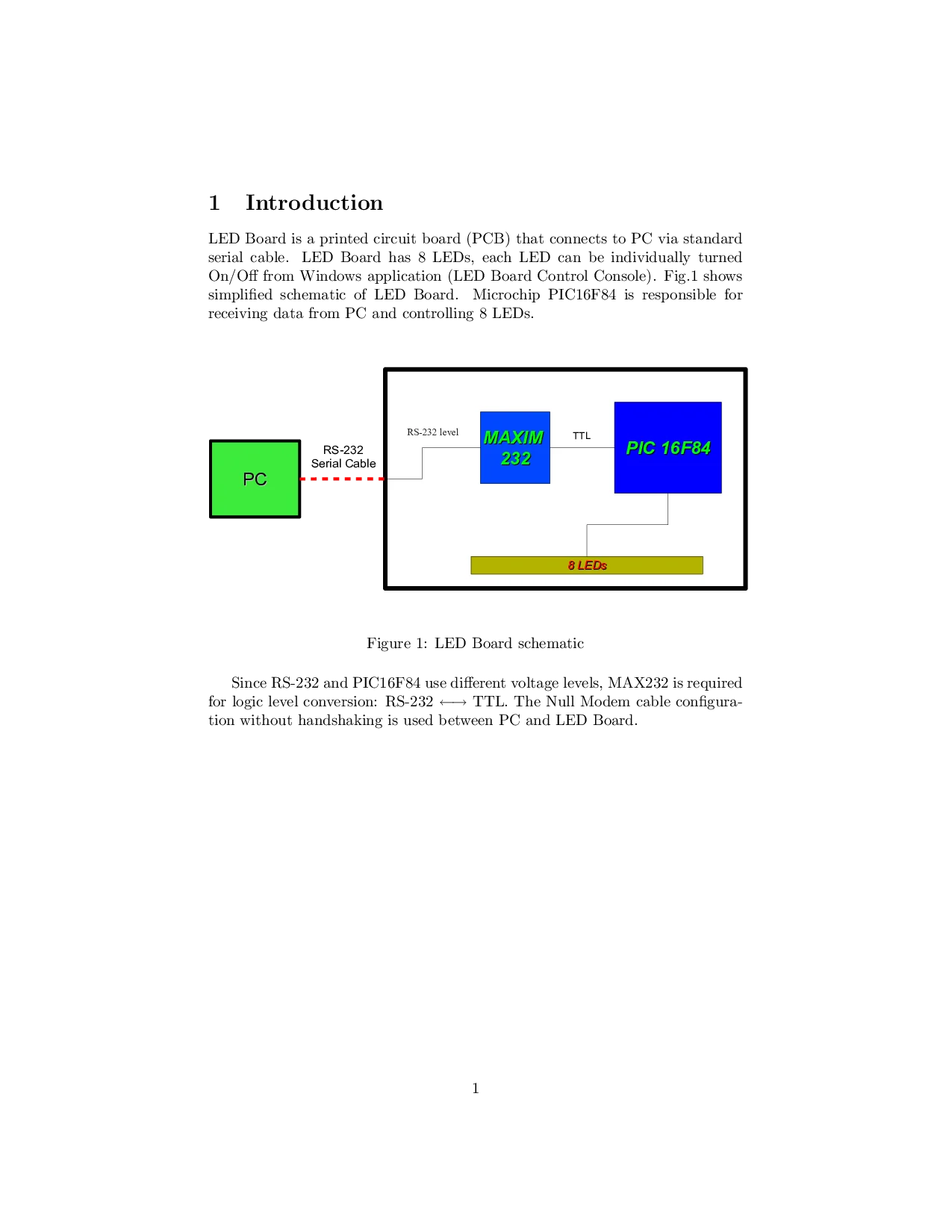
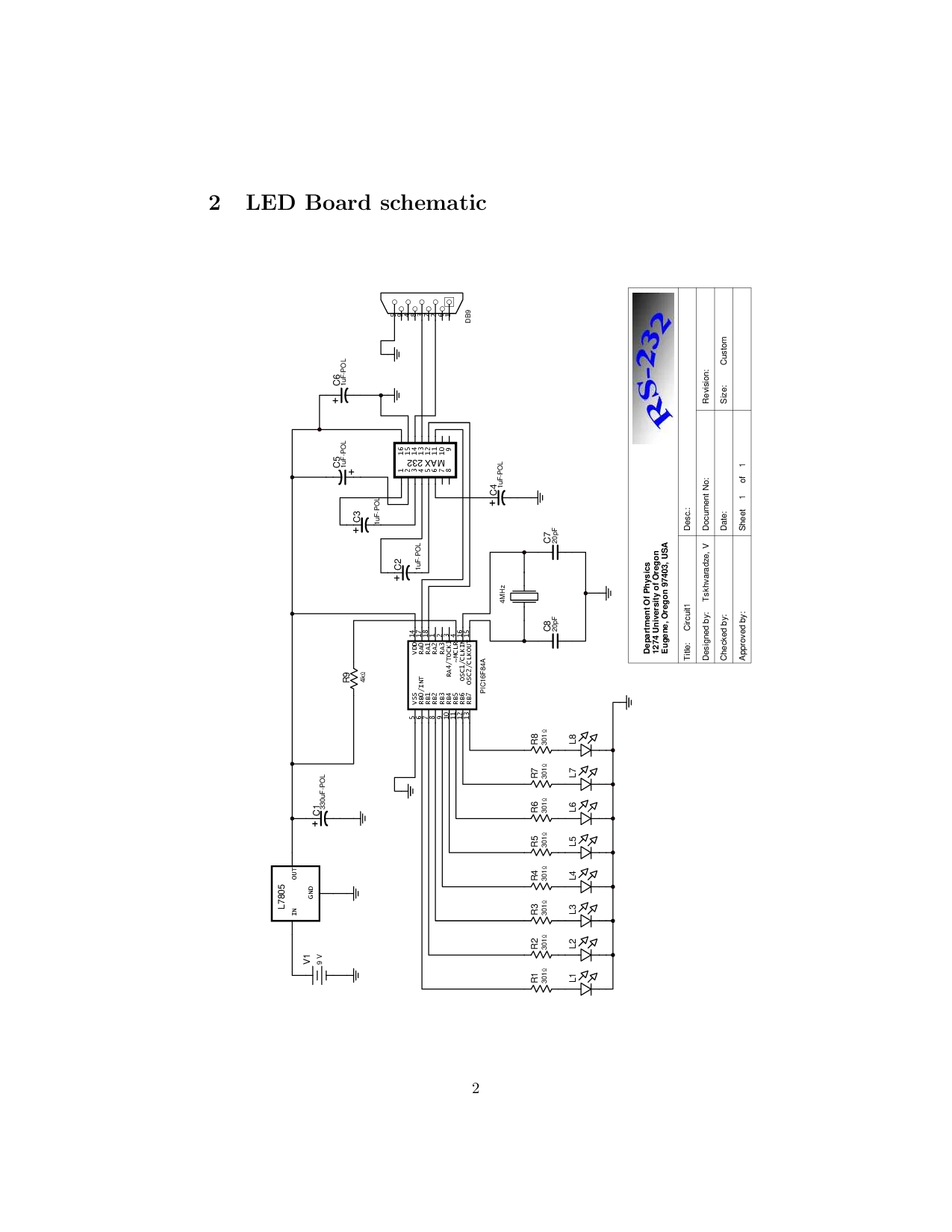
LED Board is a printed circuit board (PCB) that connects to PC via standard serial cable. LED Board has 8 LEDs, each LED can be individually turned On/Off from Windows application (LED Board Control Console). Fig. 1 shows simplified schematic of LED Board. Microchip PIC16F84 is responsible for receiving data from PC and controlling 8 LEDs. Size: Above program receives bytes and depending on bit pattern of each byte switches corresponding LEDs On/Off. For example, if received byte is 00010100, LED #3 and LED #5 will be switched On, while remaining LEDs will be Off (1 = LED ON, 0= LED OFF). Obviously, to light up all 8 LEDs, PIC16F84 should receive 11111111 . After SERIN receives a byte, it stores received byte in B0. Once byte has been received, it is written into PORTB with POKE command, thus switching LEDs On/Off according to above mentioned bit pattern. Since we have exactly 8 LEDs connected to PORTB (8 pins), it is easy to control them all with just one byte.
LED Board Control Console (LBCC) is a small Windows application designed to control LED Board from PC. To switch LED(s) On/Off, LBCC sends a byte with specified bit pattern into COM port. Fig. 2 shows sample application developed with Microsoft’s Visual C++.
There is nothing special with RA1, different pin can be used as well
To setup serial port other than the COM1, just pass different parameter to CreateFile e.g. “COM2”
📸 Image Gallery
Reference
This content is AI-processed based on ArXiv data.