Declarative Event-Based Workflow as Distributed Dynamic Condition Response Graphs
We present Dynamic Condition Response Graphs (DCR Graphs) as a declarative, event-based process model inspired by the workflow language employed by our industrial partner and conservatively generalizing prime event structures. A dynamic condition response graph is a directed graph with nodes representing the events that can happen and arrows representing four relations between events: condition, response, include, and exclude. Distributed DCR Graphs is then obtained by assigning roles to events and principals. We give a graphical notation inspired by related work by van der Aalst et al. We exemplify the use of distributed DCR Graphs on a simple workflow taken from a field study at a Danish hospital, pointing out their flexibility compared to imperative workflow models. Finally we provide a mapping from DCR Graphs to Buchi-automata.
💡 Research Summary
The paper introduces Dynamic Condition Response (DCR) graphs, a declarative, event‑based workflow model that extends and generalises prime event structures. A DCR graph is a directed graph whose nodes represent atomic events and whose edges encode exactly four primitive relations: condition, response, include, and exclude. In addition, each event is labelled with an action and a set of roles that are allowed to execute it. The state of a DCR graph at any moment is captured by a marking, a triple (Executed, Response, Included) of event sets. Executed events have already occurred, Included events are currently active in the workflow, and Response events are pending obligations that must eventually be fulfilled or become excluded.
The authors first revisit prime event structures (events, a partial order of causality, and a symmetric conflict relation) and then introduce Condition‑Response Event Structures (CRES) by adding a response relation and a set of initial required responses. CRES already captures weak fairness: every pending response must eventually happen or be disabled by conflict.
Building on CRES, DCR graphs relax several constraints: events may fire multiple times, the condition and response relations may be cyclic, and the conflict relation is replaced by two asymmetric relations—include (→+) and exclude (→%). These dynamic inclusion/exclusion relations allow a workflow to enable or disable events on the fly, which is essential for modelling loops, optional steps, and ad‑hoc changes without exploding the graph size.
Execution semantics are defined as a labelled transition system (LTS). A transition from marking M to M′ by firing event e is permitted iff: (1) e is currently included, (2) all its condition predecessors are already executed, (3) e is not blocked by an unmet condition, and (4) the role of the executing principal matches one of e’s assigned roles. Firing e updates the marking by (a) adding e to Executed, (b) adding all e’s response successors to the Response set, (c) applying include/exclude edges to modify the Included set, and (d) possibly removing e from Response if it was pending.
A run (finite or infinite) of the LTS is accepting when no response event remains forever included and pending. This acceptance condition precisely captures weak fairness for DCR graphs and ensures that “open obligations” cannot be ignored indefinitely.
To enable formal verification, the authors present a constructive translation from any DCR graph into a Büchi automaton. The translation introduces τ‑transitions (silent moves) to represent internal state changes and to guarantee that finite accepting runs are also represented in the automaton. Consequently, standard model‑checking tools for ω‑regular properties can be applied directly to DCR‑derived automata.
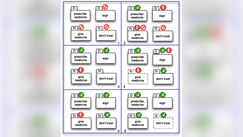
A concrete case study from a Danish hospital illustrates the practical benefits. The workflow involves three activities: Prescribe, Sign, and Give. An imperative model would require a rigid sequence or a complex loop with many guards. Using DCR graphs, the authors encode: (i) a condition edge from Prescribe to Sign (Sign may only occur after a prescription), (ii) a response edge from Prescribe to Sign (every prescription must eventually be signed), (iii) an include edge from Sign to Give (once signed, the Give activity becomes enabled), and (iv) an exclude edge from Give to Prescribe (prevent further prescriptions after medication has been given). Roles are assigned so that only doctors may execute Prescribe/Sign, while nurses may execute Give. The resulting graph clearly visualises the flexibility (multiple prescriptions before signing, repeated signing, optional giving) and the constraints (no giving before signing).
The paper also discusses related work, notably LTL‑based declarative languages and the Process Matrix model used by the authors’ industrial partner. Compared with LTL, DCR graphs avoid the need for users to write temporal formulas; the graphical notation directly reflects the underlying semantics. Compared with the Process Matrix, DCR graphs add explicit dynamic inclusion/exclusion and a formal operational semantics, enabling rigorous analysis.
In conclusion, DCR graphs provide a compact, expressive, and analyzable framework for declarative workflow modelling. They combine the readability of a graph‑based visual language with the rigor of a formal transition system and the verification power of Büchi automata. Future work outlined includes tool support for automatic translation, scalability studies for large distributed workflows, and integration with runtime monitoring systems to allow on‑the‑fly adaptation of the graph in response to real‑world events.
Comments & Academic Discussion
Loading comments...
Leave a Comment