A Novel EM Gradiometric Surveying System for Geophysical Reconnaissance
Interferometric principles are widely used in precision physics experiments and/or in advanced laboratory-based phase measurement systems. Phase resolution of such systems is a few orders of magnitude higher compared to that of standard mixer-based quadrature demodulators or lock-in technique. The first attempt of applying interferometric signal processing to transmitter-target-receiver based electromagnetic (EM) surveying in geophysical prospecting is described. It is shown that it is possible to build an EM single carrier surveying system that is, firstly, immune to amplitude variations of both the primary and the secondary EM fields, and, secondly, can directly measure phase variations between the primary and secondary EM fields. Its inherent phase noise floor, if limited by the interferometer itself, can be as low as tens of nanoradians/\surdHz or below -140 dBc/\surdHz level. A practical example of an EM gradiometric surveying system based on an interferometric principle and operating in the Extremely Low Frequency (ELF) range, is presented. The system has been tested in regional outback Australia, in the presence of a highly conducting overburden, in the search of a nickel sulphide deposit. Key words: EM gradiometer, interferometric methods, geophysical prospecting
💡 Research Summary
The paper introduces a novel electromagnetic (EM) gradiometric surveying system that leverages interferometric techniques traditionally used in precision physics to achieve high‑resolution phase measurements in the Extremely Low Frequency (ELF) band (≈1–20 Hz). Conventional transmitter‑target‑receiver EM surveys rely on quadrature demodulation, where the in‑phase component dominates and the quadrature component—carrying valuable conductivity information—is often buried beneath amplitude variations and noise. By adapting a Mach‑Zehnder‑type RF/microwave interferometer, the authors create a system that directly measures the phase difference between the primary (Bₚ) and secondary (Bₛ) EM fields, rendering it immune to amplitude fluctuations of both fields.
The architecture consists of a single carrier source feeding a power splitter (the transmitter coil, Tx). The target acts as a Device Under Test (DUT) that imposes a phase shift on the secondary field. Two interferometer arms—identical in length and components—carry the signals to a four‑port power combiner. Each arm contains a precision digital phase shifter, an attenuator, a hard limiter, and a low‑pass filter. The limiter suppresses amplitude variations, while the filter extracts the first harmonic, preserving only phase information. At the combiner, the two signals are balanced so that the “dark port” output is near zero; the residual signal is amplified by a low‑noise amplifier (LNA) and mixed with a reference signal that has been shifted by an additional 90°. Any phase change in the DUT therefore produces an output voltage directly proportional to that change.
Key performance metrics stem from the interferometer’s intrinsic phase noise, which scales inversely with the input power. Operating the ELF system with a 10 A peak current (≈1 kW transmitted power) yields a theoretical phase‑noise floor of tens of nanoradians per √Hz, corresponding to better than –140 dBc/√Hz. The digital phase‑shifter/feedback loop (DPI controller) maintains arm balance with a resolution of a few parts per billion, enabling detection of minute conductivity variations. Because both arms are symmetric, carrier frequency drift and temperature‑induced phase‑amplitude coupling cancel, further improving stability.
The prototype hardware integrates two concentric transmitter coils (Tx₁, Tx₂) and four receiver coils (Rx₁–Rx₄) mounted on a non‑conductive frame, spaced 0.5 m apart. Each coil is wound on high‑permeability cores, resonant near 1 kHz, with 100 turns and driven at 10 A peak. By pairing Rx₁‑Rx₂ and Rx₃‑Rx₄, the system simultaneously measures four second‑order gradient components (Bₓz, B_yz, Bₓₓ, B_yy). A non‑symmetric interferometer version was initially tested, but the fully symmetric configuration described above offers superior common‑mode rejection.
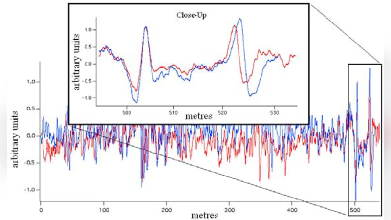
Field trials were conducted in outback Australia over terrain with a highly conductive overburden, targeting a known nickel‑sulphide deposit. The system was mounted on a trailer towed behind a 4‑WD vehicle. Data were collected at a constant speed of ~4 km h⁻¹, with measurements taken every 5 m (10 s integration). Duplicate runs (red and blue data sets) showed strong correlation, confirming that the recorded signals reflected true conductivity gradients rather than random noise. Anomalies detected along the Giles Nickel Prospect correlated with independent geological expectations, and the system identified additional unexplained features that were invisible to conventional mobile‑loop EM (ML‑EM) surveys operating at 2.08 Hz with 200 m loops.
Operational observations highlighted a morning‑time signal drift caused by partial sunlight exposure of the receiver coils; shielding the receiver section mitigated this effect. Polarity reversals observed on some lines further validated the gradiometric nature of the measurements. Overall, the interferometric ELF EM gradiometer demonstrated the ability to (i) suppress amplitude‑related noise, (ii) achieve sub‑nanoradian phase resolution, (iii) acquire multiple gradient components simultaneously, and (iv) operate from modest‑size platforms (small helicopter or medium‑size vehicle).
The authors acknowledge that full commercial exploitation requires extensive modelling to convert raw phase data into quantitative conductivity maps, robust automated calibration, and integration of the digital signal processing chain into a real‑time workflow. Ongoing work includes a laboratory‑tested symmetric interferometer version, refined calibration strategies, and deployment of a compact helicopter‑mounted variant. The promising field results suggest that interferometric ELF EM gradiometry could become a powerful tool for mineral exploration, groundwater studies, and environmental monitoring where deep, conductive targets are obscured by highly conductive overburden.
Comments & Academic Discussion
Loading comments...
Leave a Comment