A graphical environment to express the semantics of control systems
We present the concept of a unified graphical environment for expressing the semantics of control systems. The graphical control system design environment in Simulink already allows engineers to insert a variety of assertions aimed the verification and validation of the control software. We propose extensions to a Simulink-like environment’s annotation capabilities to include formal control system stability, performance properties and their proofs. We provide a conceptual description of a tool, that takes in a Simulink-like diagram of the control system as the input, and generates a graphically annotated control system diagram as the output. The annotations can either be inserted by the user or generated automatically by a third party control analysis software such as IQC$\beta$ or $\mu$-tool. We finally describe how the graphical representation of the system and its properties can be translated to annotated programs in a programming language used in verification and validation such as Lustre or C.
💡 Research Summary
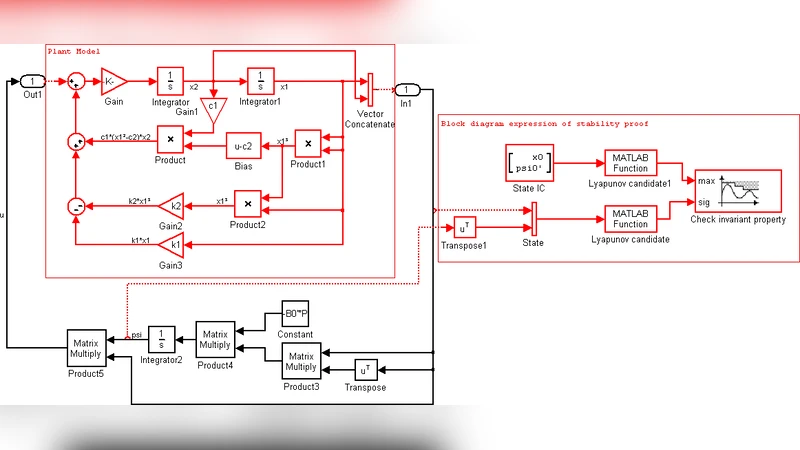
The paper proposes a unified graphical environment that extends a Simulink‑like modeling tool with the ability to embed formal control‑theoretic proofs—such as stability, L₂‑gain, and L₁‑adaptive performance bounds—directly into the block diagram. The authors argue that a major obstacle in the verification of safety‑critical embedded controllers is the communication gap between control designers, who possess deep domain knowledge, and verification engineers, who need formal specifications for deductive analysis. To bridge this gap, the proposed framework introduces new block types (e.g., a “stability” block) and wire annotations that capture proof parameters like a positive‑definite matrix P, noise characteristics, and state variables.
The tool chain consists of a front‑end and a back‑end. In the front‑end, a Verification Block Generator takes an ordinary Simulink model as input and automatically inserts proof‑related blocks, either by pulling results from third‑party robust‑control analysis tools (IQCβ, µ‑tool) or by providing a scaffold for manual insertion when automation is not feasible (e.g., for nonlinear adaptive controllers). The new blocks are designed to be concise: a single stability block can replace dozens of elementary arithmetic and logic blocks that would otherwise be required to express the same Lyapunov inequality.
A formalism is proposed to distinguish “state” signals from auxiliary signals using a new wire type, and to mark annotation‑only elements so that they are ignored during code generation. An intermediate representation makes this distinction explicit, facilitating a systematic translation to a verification‑friendly language.
The back‑end translates the annotated diagram into Lustre or C code, preserving the proof annotations as comments or as separate specification modules. The translation must handle time discretization, especially for continuous‑time Lyapunov proofs, and the authors discuss the challenges of preserving proof validity after discretization.
Several illustrative examples are provided: (1) a basic Lyapunov stability proof for a double integrator, (2) an L₂‑gain proof involving a storage function and supply rate, (3) inclusion of a plant model at an abstract level without affecting executable code, and (4) an L₁ adaptive controller with explicit transient performance bounds. Each example demonstrates how the proposed blocks dramatically reduce diagram complexity compared with a naïve implementation using only native Simulink blocks.
The paper also outlines the integration of third‑party analysis tools. To automate extraction of required parameters (state‑space matrices, noise bounds, etc.), a parser must read the Simulink model, compute the necessary proof data, and feed it back into the graphical environment. This step relies on a well‑defined formal semantics for the extended diagram language.
In conclusion, the authors claim that their environment enables control engineers to contribute formal domain knowledge early in the design process, thereby simplifying downstream deductive verification. The work is still at a conceptual stage; future efforts will focus on formalizing the annotation language, embedding it into an existing graphical tool, building robust interfaces to analysis tools, and delivering a reliable code‑generation backend. If realized, this approach could significantly streamline the V&V workflow for safety‑critical embedded control software.
Comments & Academic Discussion
Loading comments...
Leave a Comment