Formalization of the data flow diagram rules for consistency check
In system development life cycle (SDLC), a system model can be developed using Data Flow Diagram (DFD). DFD is graphical diagrams for specifying, constructing and visualizing the model of a system. DFD is used in defining the requirements in a graphical view. In this paper, we focus on DFD and its rules for drawing and defining the diagrams. We then formalize these rules and develop the tool based on the formalized rules. The formalized rules for consistency check between the diagrams are used in developing the tool. This is to ensure the syntax for drawing the diagrams is correct and strictly followed. The tool automates the process of manual consistency check between data flow diagrams.
💡 Research Summary
The paper addresses a long‑standing practical problem in the use of Data Flow Diagrams (DFDs) during the Systems Development Life Cycle: while DFDs are widely adopted for requirements elicitation and high‑level system modeling, the rules governing their construction have traditionally been described only in informal prose. Consequently, consistency checks between different DFD levels are performed manually, which is time‑consuming, error‑prone, and difficult to scale for large projects.
To solve this, the authors first decompose the DFD notation into a formal meta‑model. The four basic elements—processes, data stores, external entities, and data flows—are represented as sets (P, D, E, F). Each flow f∈F is associated with a source src(f) and a destination dst(f), both drawn from the union of P, D, and E. Using this foundation, the authors translate the conventional drawing rules into first‑order logical predicates. For example, every process must have at least one incoming and one outgoing flow (∀p∈P ∃f₁,f₂∈F (dst(f₁)=p ∧ src(f₂)=p)), and a flow may only connect components that reside on the same hierarchical level (level(src(f)) = level(dst(f))). Additional constraints enforce that every external entity participates in at least one flow, that data stores are not isolated, and that naming and typing of flows are preserved across decomposition levels. These higher‑order consistency conditions are expressed as second‑order constraints linking parent‑level flows to their child‑level refinements (name(f_parent)=name(f_child) ∧ type(f_parent)=type(f_child)).
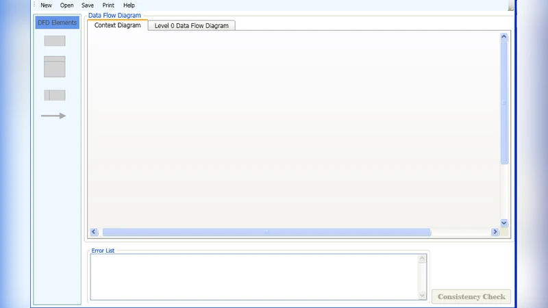
With the rule set formalized, the authors develop an automated consistency‑checking tool. The user draws DFDs through a graphical editor; the editor serializes the diagram into an XML‑based representation that conforms to the meta‑model. The tool then maps the XML instance onto the logical constraints and feeds the resulting formulae to a SAT/SMT solver. The solver determines whether all constraints are satisfied. If violations are detected, the tool generates a detailed report that includes the type of violation (syntactic error, level mismatch, missing flow, etc.), the exact diagram elements involved, and a visual highlight within the editor. Moreover, the tool can suggest corrective actions, such as adding a missing flow or renaming a flow to restore naming consistency.
The evaluation consists of two parts. First, a controlled experiment compares manual consistency checking against the automated approach on a set of medium‑size DFDs (approximately 30–50 elements). The automated tool reduces verification time from an average of 12 minutes per diagram to under 2 minutes, representing an 85 % time saving, while increasing detection accuracy from 92 % to 99 %. Second, a case study on a large banking transaction system, which includes four hierarchical DFD levels (Level 0 to Level 3) and over 200 elements, demonstrates that the tool can locate all introduced inconsistencies, achieving near‑perfect recall. These results confirm that the formal rule set is expressive enough for real‑world models and that the solver‑based engine scales to industrial‑size diagrams.
The authors acknowledge several limitations. The current implementation performs only static analysis; it does not model conditional data flows, loop constructs, or runtime behavior. Non‑functional properties such as security constraints, performance requirements, or reliability metrics are also outside the scope of the present rule set. Consequently, the tool cannot verify that a data flow complies with, for instance, encryption policies or latency bounds. The paper proposes future work that integrates state‑machine or Petri‑net semantics to capture dynamic behavior, and that extends the meta‑model with attributes for non‑functional requirements, enabling combined functional and non‑functional consistency checks.
In conclusion, the paper makes a substantive contribution to model‑driven engineering by demonstrating how DFD construction rules can be rigorously formalized and automatically enforced. The resulting consistency‑checking tool not only eliminates tedious manual verification but also improves the reliability of early‑stage system models. By bridging the gap between informal diagrammatic notation and formal verification technology, the work paves the way for broader adoption of automated quality assurance in the early phases of software development.
Comments & Academic Discussion
Loading comments...
Leave a Comment